On tunneling jobs the dynamic compactor is a surface ground-improvement tool, sized in the 5–150 t equipment class with 10–25 t tampers as the common working weight, dropped 10–25 m on a 5–8 m grid for 3–6 passes to improve granular fills to 8–12 m depth [S1].
It is specified alongside, not inside, a tunnel-bore cycle: the compactor densifies portal pads, access roads, shaft backfill, and temporary working platforms so that launch beams, segment yards, and muck-handling cranes sit on competent ground. The shield machine that bores the tunnel is a separate, depth-agnostic tool whose cutterhead can grind through 50 m of cover limited by face pressure, not by compaction physics [S1].
What the dynamic compactor actually does on a tunnel site
A dynamic compactor drops a heavy tamper weight, most commonly 10–25 t with 30–40 t units reserved for port and airfield work, from a controlled height of 10–25 m onto a defined grid, generating a stress pulse that collapses voids and rearranges granular grains into a denser packing [S1]. The technique is most effective in permeable, granular soils because cohesive soils absorb and limit the stress pulse, and high fines content or a high water table dissipates the impact pressure without grain rearrangement [S3].
Improvement depth tracks tamper weight and drop height: a 15 t weight at 20 m drop typically improves granular soils to 8–12 m depth, with 3–6 passes at 5–8 m grid spacing, leaving about 6 m diameter impact craters on the working surface that are back-bladed and re-compacted between passes [S1]. Standard U.S. practice on transportation sites uses a 10–30 t weight and 50–100 ft drop heights on a 10–20 ft grid, with the impact creating a 3–4 ft crater that is backfilled with granular material before the next drop [S3].
For a tunnel contractor the practical implication is that the compactor can treat portal platforms, segment storage yards, and muck-handling crane pads in days, not weeks, but it cannot replace a pressure sensor based face-pressure control loop on a slurry or EPB shield, because those two machines do not share a working face.
Selection gates: compactor first, shield second
Direction of work is the first gate: a shield machine removes material forward through a screw conveyor or slurry line and produces muck; a dynamic compactor displaces material downward with no spoil and produces a stable platform [S1]. If the project produces muck, the compactor is out of scope at the face; if it produces a stable working pad, the compactor is in scope and the shield is not.
Depth of effect is the second gate. Dynamic compaction reaches 8–12 m with a 15 t / 20 m drop, and goes deeper with heavier weights and greater drop heights, but improvement falls off with depth, so a 25–40 m thick loose fill usually needs pre-driven stone columns or vibro compaction in tandem [S1]. Shield excavation is depth-agnostic in the sense that the cutterhead can grind through 50 m of cover, limited by face pressure and segment handling rather than compaction physics.
Ground type is the third gate. Shields handle soft alluvium, clay, mixed face, and rock up to roughly 120 MPa UCS with the right disc cutters; dynamic compaction only works in free-draining granular soils such as sands, gravels, and demolition fills [S1][S3]. Specifying dynamic compaction over a clay or silt profile is a method-statement error, not a tolerance question.
Operating envelope and method-statement numbers
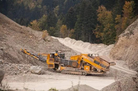
Modern tunnel construction is capital-intensive and the global tunnel construction market tracked roughly 1,275 active projects in 2022 with an average annual growth rate around 10%, about 2.5 times the rate seen in the global construction industry, which keeps pressure on contractors to lock in method statements and equipment classes early [S2]. On a tunneling project the compactor sits in a 5–150 t equipment class and runs heavy hydraulics, the same envelope as a shield machine, so site logistics for heavy lifts, crane pad prep, and utility routing are common between the two [S1].
For tunneling pile-driver work in low-headroom areas, a separate selection logic applies; see the low-headroom hammer match and vibration control guide. Vibration is the operational hazard both methods share: a dynamic compactor produces large vibrations, so adjacent facilities must be reviewed for vibration sensitivity and their pre-existing conditions documented before any drop sequence begins [S3]. Standard practice closes the cycle with penetration testing to measure the improvement achieved, and an ironing pass at 10–15 ft drop height over the whole surface to densify the loose 3–4 ft of surface soil left after the primary drops [S3].
Method-statement engineers should also expect a final surface lift to be looser than the treated profile, so a low-energy ironing pass is non-optional on tunnel portal pads where tracked cranes and segment handlers will sit.
Comparison: dynamic compactor vs shield on four decision criteria
For procurement and method-statement engineers, the practical split comes down to four gates, and the same four criteria tell you which line item a compactor lease belongs on [S1].
1. Direction of work: shield removes material forward, produces muck; dynamic compactor displaces material downward, produces a stable platform with no spoil.
2. Depth of effect: compactor reaches 8–12 m with 15 t / 20 m drops and falls off with depth; shield excavation is depth-agnostic, limited by face pressure and segment handling rather than compaction physics.
3. Ground type: shield handles soft alluvium, clay, mixed face, and rock up to about 120 MPa UCS; compactor only works in free-draining granular soils, sands, gravels, and demolition fills.
4. Output unit: shield advance is quoted in mm/min or m/day advance rate at the face; compactor output is quoted as improved depth per pass and equivalent bearing footprint per drop, typically a 20–40 t equivalent improved-bearing footprint per drop [S1].
Engineers who need a quick port-and-terminal yard spec for tracked equipment can cross-reference the backhoe loader selection map for port and terminal work, since portal-yard earthworks share a similar grid-prep logic.
Adjacent equipment in the tunneling supply chain
On a tunnel project the dynamic compactor is one tool in a chain: a flow meter on the bentonite or grout line, a pressure transmitter on the slurry circuit, a dynamic balancing machine on the cutterhead before launch, and a pressure sensor on the segment erector ram are all part of the same equipment register. Each of those instruments is governed by separate specifications, but they share a common commissioning step: a documented baseline reading before any heavy lift, drop, or thrust begins. [S1]
For portal-yard and shaft work, a diaphragm wall grab is the matching tool for the retaining wall, while a truck-mounted crane handles the segment stack. None of these substitutes for the compactor, but they all interact with the same portal pad that the compactor densifies.
Limitations, failure modes, and what to verify on site
Dynamic compaction fails in three documented ways: a high water table dissipates the impact pressure, a high fines content prevents grain rearrangement, and a thick loose fill beyond the compactor's effective depth leaves untreated soil below the treated crust [S1][S3]. Each of these is a specification error, not a contractor error, and each shows up on the penetration test that follows the ironing pass.
Vibration is the other documented failure mode: adjacent facilities, utilities, and existing tunnel linings must be reviewed for vibration sensitivity, and pre-existing conditions documented before the drop sequence begins [S3]. On urban tunneling projects this often forces a smaller tamper weight, a tighter grid, or a switch to vibro compaction entirely.
For a pressure transmitter on the slurry line or a flow meter on the grout circuit, the field test is a documented baseline at zero flow and zero pressure; for a dynamic compactor, the equivalent field test is a penetration test after the ironing pass, and a refusal reading on a 15 t / 20 m drop.
For tunneling projects the dynamic compactor is a portal-yard and shaft-plATFORM tool, sized in the 5–150 t class with 10–25 t tampers on a 5–8 m grid, useful only in free-draining granular soils to 8–12 m depth. Track the next tender for the depth-of-improvement clause (a typical 8–12 m for a 15 t tamper) and the ironing-pass specification (a 10–15 ft drop over the whole surface) as the two numbers that decide whether the compactor line item survives a value-engineering review.