
A vapor-compression heat pump is built around four refrigeration-cycle components: a compressor, a condenser, an expansion valve, and an evaporator [S3][S5]. Everything else on the bill of materials, including reversing valves, source-side pumps, accumulator, receiver, fans, and inverter electronics, exists to feed, support, or extract work from that core quartet.
The same four-block architecture shows up in air-source, ground-source, water-source, and exhaust-air variants; what changes is the source-side heat exchanger and the brine/water loop hardware around it [S1][S6][S9]. For a building-side spec, the practical question is which sub-components live inside the unit, which are field-installed, and which materials sit on each side of the refrigerant-to-air or refrigerant-to-water barrier.
Core refrigeration loop: compressor, condenser, expansion valve, evaporator
The compressor moves refrigerant through the loop, the condenser rejects heat to the conditioned space, the expansion device drops pressure to let the refrigerant boil in the evaporator, and the evaporator absorbs heat from the source (outdoor air, ground loop, or water loop) [S3][S5][S7]. The reversing valve re-routes hot gas between indoor and outdoor coils, which is what lets one unit switch between heating and cooling mode; ground-source units typically add a reversing valve to switch between heating and cooling as well [S4][S9].
Common expansion devices are thermostatic expansion valves (TXV/TEV), electronic expansion valves (EEV), and, in small residential units, fixed orifices / capillary tubes; EEVs are now the default on inverter-driven equipment because stepper control tracks the modulating compressor speed [S3]. Coils are almost universally copper tube with aluminum fin plate, joined by mechanical expansion on the fin side and brazed copper return bends; all-aluminum microchannel coils are also common on the outdoor side of residential air-source units, traded for higher pressure rating and lower refrigerant charge at the cost of galvanic compatibility with copper headers.
Bill-of-materials: metals, brazing filler, insulation, refrigerant
The structural bill of materials for a residential air-source unit is dominated by sheet steel (casing, chassis, mounting base), copper tube and aluminum fin (both coils), brazed copper or brass fittings, ABS or PP plastic for side panels and drain pans, and closed-cell elastomeric foam (Armaflex-class) for suction-line insulation [S2][S7]. Ground-source units add HDPE or PE-Xa ground loop pipe, typically SDR-11 ratings at 160 psi working pressure, plus a circulator pump and plate or coaxial source-side heat exchanger [S1][S6].
Refrigerant charge for a typical 3-5 kW residential air-source split sits in the 0.8-2.5 kg range depending on line-set length; the industry has migrated from R-410A to R-32 (GWP 675) in many new platforms, with R-290 (propane, GWP ~3) specified in small monobloc and window units where charge is held below 150 g for IEC 60335-2-40 compliance [S3][S4]. Adsorption and thermally driven heat pumps replace the compressor-driven loop with a sorbent bed, where the working pair is typically zeolite, silica gel, or activated carbon, which materially changes the bill of materials on the thermal side [S2].
Control, power electronics, and inverter hardware
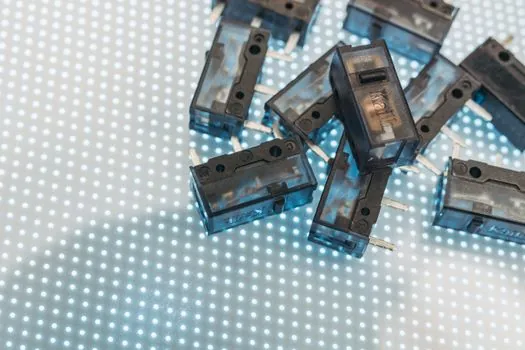
Modern units are inverter-driven, meaning a variable-frequency compressor motor and a switched-mode power stage replace the on/off contactor of legacy single-speed designs [S3][S7]. The control board hosts EEV stepper drivers, current sensors, IPM/IGBT power modules, a DC link capacitor bank, and communication interfaces (Modbus, CAN, or proprietary bus); the same board usually runs the defrost algorithm, reversing-valve solenoid, and outdoor-fan BLDC driver.
Sensors on the refrigerant loop are the other recurring BOM line: NTC 10 kohm thermistors on suction, discharge, liquid, and outdoor-air/coil points, plus a high-pressure switch, a low-pressure transducer, and, on inverter compressors, discharge thermistors embedded in the scroll/volute for electronic protection [S7]. On the water side of a hydronic or ground-source unit, a flow switch and a temperature/pressure well complete the safety chain; reverse-cycle units additionally wire a 4-way reversing valve solenoid at 230 V AC or 24 V DC depending on platform.
Source-side and load-side heat exchangers: materials by medium
For air-source units, both coils are fin-and-tube; for water-source units, the source-side heat exchanger is typically a brazed-plate heat exchanger (stainless 316 plates, copper brazing) or a coaxial shell-and-coil, sized for 5-10 K approach temperature at part load [S6]. The air-side coil material is almost always copper tube with aluminum louvered fins, and the assembly is mounted in a hot-dip-galvanized or pre-coated steel chassis.
Ground-source (GSHP) systems put HDPE/PE-Xa ground loop in the ground, a plate or coaxial source-side heat exchanger indoors, and a circulator pump with line-set isolation valves [S1][S6]. Closed-loop systems use a propylene glycol/water mixture (typically 25-30% PG) to depress the freezing point; open-loop systems draw well water directly through a plate heat exchanger, which is cheaper but requires water chemistry control to prevent scaling and fouling [S6]. A useful spec anchor for the indoor side of a hydronic system is the plate heat exchanger form factor, since the same 316/Cu-brazed plate also appears in domestic hot water preheat and in pool/spa coupling.
Compressor types and refrigerant compatibility

Compressors in residential and light-commercial heat pumps are dominated by hermetic scroll, with rotary/vane types used at the smallest capacities and screw or centrifugal machines appearing in the 100 kW+ industrial range [S7]. Scroll compressors tolerate liquid slugging better than reciprocating designs, which is why they became the default when R-410A and later low-GWP refrigerants pushed operating pressure ratios up. Inverter control modulates speed over a 25-110 Hz range, matching capacity to load without on/off cycling and giving a wider part-load COP envelope.
For high-temperature industrial heat pumps (district heating, process steam), screw or centrifugal compressors using ammonia (R-717) or CO2 (R-744) in transcritical cycles are the typical platform, and the bill of materials skews heavily toward carbon-steel pressure vessels, plate heat exchangers, and large electric motors in the 50-500 kW range. For the 3-5 kW residential split platform, the housing/cabinet sheet metal is usually a construction machinery and equipment-style cold-rolled steel with powder coat, sharing stamping and bending processes with HVAC cousins but not with mobile construction plant.
Comparison: air-source split vs monobloc vs ground-source BOM
Three reference BOM profiles help a spec engineer anchor procurement and weight. By materials mix on a typical 5 kW heating unit: air-source split, 65-75% of mass is steel, copper, and aluminum in roughly 4:2:1 ratio, with refrigerant charge under 2 kg and plastics/elastomer at 5-8% [S3][S4]. Air-source monobloc removes the field refrigerant line-set, adds a single outdoor cabinet, and typically runs on R-290 with a 0.5-1.0 kg charge cap. Ground-source splits that BOM heavily toward HDPE/PE-Xa ground loop, plate heat exchangers, and circulator pumps, with much less fin-and-tube mass.
By installation footprint: air-source split needs an indoor air handler, outdoor unit, refrigerant line-set, and condensate drain; monobloc needs only hydraulic connections on the indoor side; ground-source needs boreholes or horizontal trenches, a ground loop manifold, and an indoor mechanical room for the heat pump unit, pump, and source-side heat exchanger [S1][S6]. On a lifetime basis, ground-source units carry higher civil works cost (loop field, drilling) but typically achieve higher SPF (seasonal performance factor) values, often 3.5-4.5, because the source temperature is more stable than ambient air [S1][S7].
Standards, codes, and selection signals
Refrigerant flammability drives the bulk of the safety code work: IEC 60335-2-40 governs household heat pumps and limits A3 (propane/R-290) charge based on room area and ventilation. Air-source units sold in Europe carry CE marking under the Low Voltage, EMC, and Pressure Equipment Directives, and outdoor units rated for cold-climate operation are commonly tested to EN 14511 for declared capacity and COP. The COP itself is the simple ratio of delivered heat to consumed electricity; per [S4], modern equipment transfers 1-4.5 kWh of heat per 1 kWh of electricity, and a heat pump tied to a fossil-free grid can satisfy a large fraction of building heating demand at lower carbon footprint than a gas condensing boiler [S4].
Field failures trace to a small set of recurring root causes: refrigerant undercharge from line-set leaks, EEV hunting under partial load, inverter IGBT stress from grid disturbances, outdoor-coil fin fouling in coastal/urban air, and reversing-valve solenoid failure on cycling units [S7]. For buyers, two trackable signals going into late 2026 are the spread of R-32 in mid-tier European platforms and the move toward R-290 monoblocs in the 4-9 kW segment, both of which compress the refrigerant-side BOM and shift risk from GWP to flammability management. Related EV Charger Key Components and Bill of Materials Map follows the same inverter-and-control BOM pattern at much higher power, and the PVC-U Pipe Selection for Schools reference covers a comparable pressure-class-and-temperature spec exercise on the hydronic distribution side.
For the relevant spec sheets and selection criteria, see shaft key.