The signal path inside an inductive proximity sensor is a four-block chain: ferrite core with coil, LC oscillator, Schmitt trigger, and output amplifier, all housed in nickel-plated brass, stainless steel, or PBT plastic [S1].
Switching speed for the chain sits between 10–20 Hz on AC-powered units and 500 Hz to 5 kHz on DC-powered units, with sensing range from fractions of a millimetre out to about 60 mm on standard parts [S1]. The Schmitt trigger is the block that decides when the LC oscillator's amplitude collapse counts as a "target present" event.
What the LC oscillator actually does on the sensing face
The oscillator drives a high-frequency current through a coil wound on a ferrite core, concentrating the field at the sensor's face [S2]. When a metal target enters that field, eddy currents induced in the target draw energy out of the tank circuit, the oscillation amplitude drops, and at sufficient target proximity the oscillation collapses entirely. The well-known name for this is the Eddy Current Killed Oscillator, or ECKO, principle [S1].
Schematic references break the front end into a coil plus ferrite-core LC oscillator block, feeding a signal-shaping block, feeding an output stage [S2]. For very high-speed detection of small copper projectiles, the design constraint becomes keeping coil reactance low so the oscillator recovers fast; the relevant rise time has to be in the tens of microseconds for a 900 m/s bullet crossing a one-centimetre coil window in roughly 11 microseconds [S3].
Why the Schmitt trigger, not a plain comparator
A Schmitt trigger is a comparator with two thresholds, an upper threshold (UTP) for the rising edge and a lower threshold (LTP) for the falling edge, built by applying positive feedback around a comparator so the loop gain is greater than one [S5][S8]. The gap between UTP and LTP is the hysteresis band, and the output only changes state when the input crosses one of those two lines [S5].
That hysteresis is the whole reason a Schmitt trigger sits between the LC oscillator and the output amplifier on an inductive proximity sensor: the oscillator's amplitude does not collapse in a clean step, it droops through a noisy region as the target approaches, and a single-threshold comparator would chatter on the noise. The Schmitt trigger's dual threshold makes the output change state once, cleanly, on target entry and again, cleanly, on target exit [S5][S6]. The same hysteresis is what lets the trigger reject mechanical contact bounce in switches, which is its other classic use [S5].
From Schmitt trigger edges to a usable output
Once the Schmitt trigger flips, the output stage drives the sensor's output line. With a normally open configuration the line goes high when the target enters the sensing zone; with normally closed the line goes low on target entry [S1]. The external reader is typically a PLC, motion controller, or smart drive that converts the binary state into usable machine data [S1].
Commercial inductive sensors expose this chain as a 2-wire or 3-wire DC or AC/DC interface, with operating distances classed as standard or increased, housings from L04 to M30 cylindrical or Q08 to Q80 rectangular, and allowable temperature up to 120°C with allowable pressure up to 500 bar in the high-spec product lines [S2]. The same front-end oscillator and Schmitt-trigger chain is what is being repurposed in non-contact position measurement, where the proximity probe family extends the inductive principle to high-resolution eddy-current displacement gauging rather than simple go/no-go detection.
Block diagram and signal flow in one picture
Putting the four blocks in order: ferrite-core coil, LC oscillator, signal-shaping Schmitt trigger, output amplifier, target feedback through eddy-current loss [S1][S2]. The classic patent literature describes the same chain as an oscillator/demodulator arrangement followed by a Schmitt trigger stage that converts the demodulated amplitude into a logic level, with current-mirror biasing setting the trigger thresholds [S4].
For a clean write-up of the signal path on a datasheet, the four blocks map to the four rows of a functional block diagram: coil and ferrite core, LC oscillator, signal-shaping stage (Schmitt trigger), and output stage [S2]. Engineers reading a sensor datasheet should expect the threshold hysteresis, output topology (NPN/PNP, push-pull, NO/NC), and switching frequency to be specified at this stage of the chain, not at the coil.
Options on the same front end: discrete vs ASIC vs modulated carrier
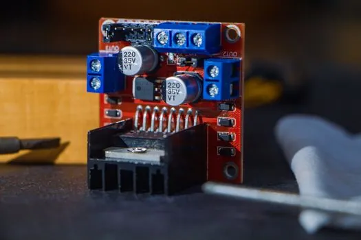
Three common implementations sit on the same LC-oscillator-plus-Schmitt-trigger foundation. Discrete front ends use a transistor LC oscillator with a separate comparator IC for the trigger stage; these are the easiest to modify for unusual coil geometries or for fast prototyping [S3]. Integrated front ends put the oscillator, demodulator, and Schmitt trigger on one ASIC, which is what most commercial M12, M18, and M30 tubular inductive sensors use, giving repeatable UTP and LTP thresholds across production lots [S2][S4].
A useful comparison on three decision criteria: discrete front ends win on flexibility and on the ability to push switching frequency toward the 5 kHz DC ceiling, but they drift with temperature; integrated ASIC front ends win on threshold repeatability and on immunity to supply variation, at the cost of a fixed coil driver topology; modulated-carrier inductive sensors add a demodulator between the LC oscillator and the Schmitt trigger to recover amplitude at a known carrier frequency, which is the path used when the solenoid coil geometry is being repurposed for position rather than go/no-go sensing. The trade-off in each case is between tuning freedom, threshold stability, and noise rejection on the Schmitt-trigger input.
Limits, failure modes, and what to watch on the bench
Maximum switching frequency is bounded by the LC oscillator's recovery time after a target exits the field; once the hysteresis band is fixed, the trigger can only flip as fast as the oscillator amplitude rebuilds [S1][S3]. Sensing range is bounded by coil geometry, with standard tubular inductive parts covering fractions of a millimetre to 60 mm and specialty long-range parts going further [S1].
Common bench failures trace to three specific causes: the hysteresis band set too narrow, which lets supply-noise ripple on the oscillator amplitude cross the trigger threshold and produce chatter; the UTP and LTP both drifting with temperature, which forces a re-spec of the sensor's operating distance; and the output stage sinking or sourcing more current than its rating, which collapses the internal rail and starves the oscillator. Checking the trigger thresholds with an oscilloscope on the Schmitt trigger input, then verifying clean edges at the output stage with a checking and testing apparatus such as a scope or logic analyser, is the standard verification path. For stainless or PBT-housed sensors mounted on construction machinery and equipment, the same three checks apply, with the addition of vibration and IP-rated sealing on the housing side.
Standards, sourcing, and what to confirm on the datasheet

No single IEC or ISO standard governs the internal oscillator-to-Schmitt-trigger signal chain itself; the governing documents are the sensor-level performance standards and the enclosure/EMC standards the part is certified to [S1][S2]. Datasheets for commercial inductive sensors typically cite switching frequency in Hz, sensing range in mm, hysteresis as a percentage of Sr (the nominal sensing distance), and supply voltage range, with housing material and IP rating called out separately [S1][S2].
For sourcing, the realistic envelope for a standard 8 mm or 12 mm tubular DC inductive sensor is a few dollars at the low end, with the high-temperature 120°C or 500 bar versions commanding a meaningful premium because of the stainless or ceramic front face [S2]. When the application is detection of fast-moving non-ferrous targets, the design constraint shifts to coil reactance and trigger slew rate, not to standard sensing range, and a discrete front end with a tunable Schmitt trigger stage is the typical starting point [S3].
Related analysis: Conductive vs Dissipative ESD Flooring: Resistance Bands, Use Cases, and Selection Rules.