Industrial pump manufacturing in 2026 still resolves to a six-station workflow — foundry, machining, rotor assembly, balancing, hydrotest, and performance witness test — with API 610 (centrifugal), API 674 / API 675 (positive displacement), and ISO 5199 acting as the controlling specs on over 80% of the process pumps shipped to hydrocarbon, chemical, and water utilities [S1][S2].
The dominant process categories supplied globally remain centrifugal (end-suction, between-bearings, vertical turbine), positive displacement (progressive cavity, lobe, gear, screw), and specialty designs (submersible, mag-drive, peristaltic) [S1][S2][S3].
Stage 1 — Casting and Forging: Casing, Impeller, and Wear-Part Stock
The first make-or-break step on the shop floor is getting the raw stock right; for centrifugal pumps the casing and impeller are produced as castings — typically on a V-process line for medium-to-high volumes, or in green-sand moulds for short runs — in ASTM A48 Class 30/40 gray iron, ASTM A216 WCB carbon steel, or ASTM A743 CF8M / CF3M stainless, with duplex (ASTM A890 4A / 5A) specified for chloride and seawater service above 60 °C [S1][S3].
Progressive-cavity and lobe-pump housings take a different route — machined bar-stock or fabricated steel plate — because the elastomer stator liner (typically FKM, HNBR, or EPDM) is bonded into a precisely bored housing, with Flosys and similar suppliers producing both metal rotor and rubber-stator subassemblies in-house [S1].
Forging dominates the high-pressure and high-speed end: API 610 overhung pumps with 16 bar+ casings, and all barrel-case multistage pumps, are typically forged in ASTM A182 F11 / F22 / F316L and then weld-repaired per ASME Section IX qualified procedures before machining.
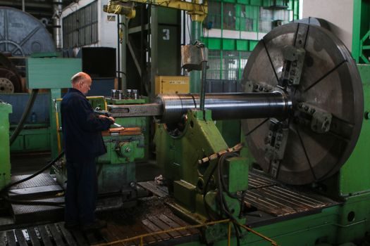
Stage 2 — CNC Machining: Tolerances, Surfacing, and Hydraulic Finish
Once the castings clear radiographic inspection (ASTM E446 reference radiographs for cast iron, ASTM E192 for welds), they move to CNC machining where critical interfaces — the bearing housing register to ISO 286 H7, the impeller keyway, the casing flange serration, the mechanical-seal chamber to fit ANSI B73.1 / B73.2 dimensions — are held to single-digit micron tolerances on horizontal machining centres, with internal passage finish spot-checked using an industrial borescope where geometry permits [S1][S2].
Impeller vanes are roughed out, then finish-profiled on 5-axis milling centres to within ±0.1 mm of the designed hydraulic passage; surface roughness on wetted passages is commonly pushed to Ra 0.8 µm or better, because hydraulic efficiency on a 50 mm closed impeller can move 1.5–2 percentage points for every Ra grade tightened [S2].
Hard-facing on solids-handling and slurry pumps is its own sub-process: high-chrome white iron (ASTM A532 Class III Type A) or tungsten-carbide overlay is deposited on the casing cut-water and impeller shrouds, then ground to print thickness, giving the typical 25–30% Cr content that resists abrasive wear in mining and dredge service.
Stage 3 — Rotor Assembly, Bearings, and Mechanical Seal Fitment
Rotor stack-up is the engineering heart of the build: shaft diameter, bearing span, and first-critical-speed margin are calculated to keep the operating speed at least 20% below the first lateral critical, with SKF / FAG / NSK deep-groove and angular-contact bearings fitted to ISO 492 Grade 6 (ABEC 3) or Grade 5 (ABEC 5) depending on the speed class [S2].
Mechanical seal chambers are bored to API 682 Type A / B / C dimensions so that any seal from the qualified vendor list drops in without a re-machining step; this is the single biggest reason why process-plant owners standardise on API 682 seal chambers across their centrifugal pump fleet.
Lobe and progressive-cavity pump rotors are a different mechanical conversation: the metal rotor of a PC pump is a single-threaded helical profile, hard-chrome plated to 25–50 µm and ground to a concentricity under 0.02 mm, then paired with a moulded elastomer stator — a matching pair of opposing hand that establishes the sealed cavities which give the pump its name [S1].
Stage 4 — Balancing and Laser Alignment
Every rotating assembly — impeller-shaft, rotor-shaft, and bare shaft on a coupling-fit design — is dynamically balanced on a hard-bearing or soft-bearing balancer to ISO 1940-1 G2.5 for pumps running above 3,000 rpm, with G6.3 accepted on slow-speed positive-displacement units [S2].
Tri-Rotor's variable-volume 80BV head rotor, used on crude-oil wells in Oklahoma, is balanced as a complete cartridge so the field-replaceable head can be swapped without re-balancing the drive end — a serviceability lever that materially cuts mean-time-to-repair on remote well-sites [S2].
For close-coupled and mag-drive pumps where the motor shaft and pump shaft are coupled through a spacer or a permanent-magnet coupling, balancing grade drops to G1.0 on the bare assembly; any residual unbalance below 1 g·mm/kg is generally accepted as inaudible at the API 610 noise limit of 85 dB(A) at 1 m.
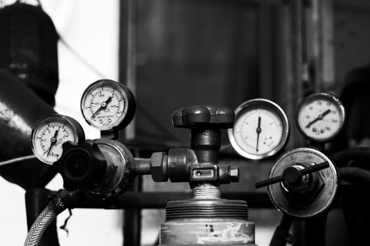
Stage 5 — Hydrostatic Test and Performance Witness
Every wetted-pressure-containing casing is hydrostatically tested at 1.5× the design pressure (or 1.5× the maximum allowable working pressure, MAWP) for a minimum of 30 minutes, with the API 610 baseline of 1.5× design pressure × 10 minutes being a common floor; cast-iron casings are usually tested with water at ambient, while alloy and clad casings sometimes demand a lower test temperature to avoid brittle fracture [S1][S2].
Performance testing follows ISO 9906:2012 — the current global standard for centrifugal pump acceptance tests — with three tolerance classes available: Grade 1 (±5% on flow, ±5% on head at the duty point) is the contractual default; Grade 2 (±8% / ±8%) is common on municipal water pumps where the spec is less demanding; Grade 3 is the broadest envelope and is rarely accepted on process pumps, with the flow, pressure, and power transducers on the witness loop pre-calibrated against a multifunction process calibrator traceable to NIST before each run [S3].
Hydrotest fixtures and witness-test loops at full-service fabricators (e.g. Industrial Pump Manufacturing's Chico, CA facility) hold the test tank, calibrated flow meter (typically magnetic or ultrasonic, traceable to NIST), suction and discharge pressure instrumentation, and power analyser to the same standard the customer is buying to [S3].
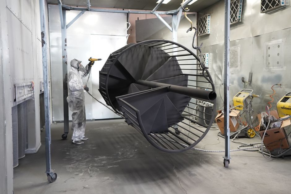
Stage 6 — Surface Treatment, Nameplate, and Shipment
Final finishing is spec-driven: municipal water pumps get a two-part epoxy at 250–350 µm DFT over SSPC-SP6 commercial blast; chemical and offshore pumps get a glass-flake vinyl ester or a zinc-rich primer plus epoxy build-up; food and pharmaceutical pumps are electropolished to Ra ≤ 0.5 µm on all wetted 316L surfaces [S3].
Nameplates follow ISO 9905 / ISO 5199 data fields — manufacturer, model, serial, rated flow / head / speed / power, maximum allowable working pressure, and the year of build — and the pump ships with a documented data book: material certificates (EN 10204 3.1 for pressure parts), balancing report, hydrotest chart, performance test report, and the full drawing package [S1][S2][S3].
For a side-by-side look at how process pumps compare against hydraulic pumping units on digital commissioning and IIoT integration, see the hydraulic smart-manufacturing 2026 cut; for adjacent rotating-machinery spec levers, the bearing smart-manufacturing 2026 reference lines up the sensor, tolerance, and sourcing questions on the bearing side of the same rotor train.
Selection Criteria: Centrifugal vs Positive-Displacement vs Specialty
Decision tree: clean, low-viscosity, high-flow service (water, light hydrocarbons, dilute chemicals) maps to centrifugal — typically API 610 OH2 / VS6 or ISO 5199 end-suction; viscous, shear-sensitive, or solids-laden service (crude, polymer, sludge, food paste) maps to positive displacement — progressive cavity or lobe per [S1][S2].
Four decision criteria line the three families up cleanly: (1) viscosity ceiling — centrifugal falls off above ~200 cSt, PD holds to 50,000 cSt and beyond; (2) solids-handling — open-impeller centrifugal passes 5–10 mm spheres, PC pumps with a sized rotor/stator pass 30–50 mm; (3) flow vs pressure characteristic — centrifugal gives high flow at modest head, PD gives near-constant flow against variable head, screw and lobe reach 16 bar routinely while PC pumps span 6–24 bar standard build; (4) metering accuracy — PD units hold ±1% flow accuracy without instrumentation, centrifugal needs a flow control valve or VFD.
Specialty designs close the gaps: mag-drive (metallic or SiC containment shell, no seal) for zero-leakage chemical service; submersible with IP68 motor for mine and stormwater; peristaltic for abrasive slurries where the hose is the only wearable.
What the Process Does NOT Solve
Even a clean factory build cannot rescue a mis-specified duty point: NPSH margin below 0.5 m, or a process fluid with entrained gas above ~2% by volume, will cavitate or de-prime a centrifugal pump regardless of how well it was machined and balanced; this is why the witness test is run on the actual process water (or a close simulant) at the site, not just on clear water in the shop [S1][S3].
Lead times on cast duplex and super-duplex casings remain a constraint — 18–28 weeks from pour to machined casting is normal in 2026, with ASTM A890 6A (25% Cr super duplex) routinely extending to 36 weeks on the first article, which is why fleet operators hold safety stock or release long-lead items on engineering-procurement-only contracts.
Trackable signals to watch through 2026: the take-up of API 682 Category 3 cartridge seals on chemical pumps, the broadening of the 3D-scanned impeller finishing cells at major manufacturers, and the migration of municipal water-pump specifiers from hydraulic institute HI 9.6.6 to ISO 9906:2012 Grade 2 as the acceptance baseline.