Centrifugal pumps move fluid via one or more impellers spinning inside a volute, classifying them as dynamic turbomachinery and making them the most common process pump by installed count for water, sewage, petroleum, and petrochemical service [S1].
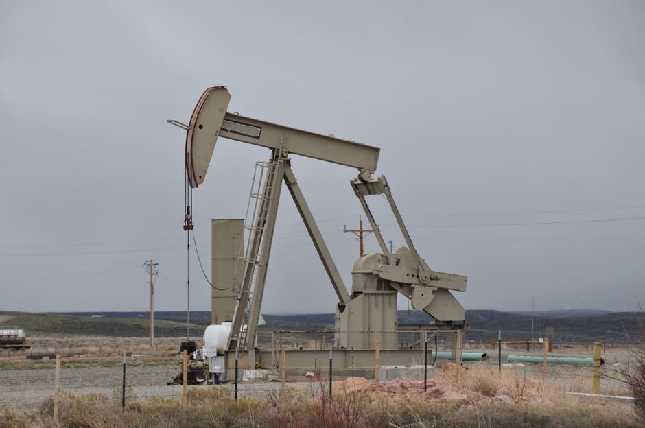
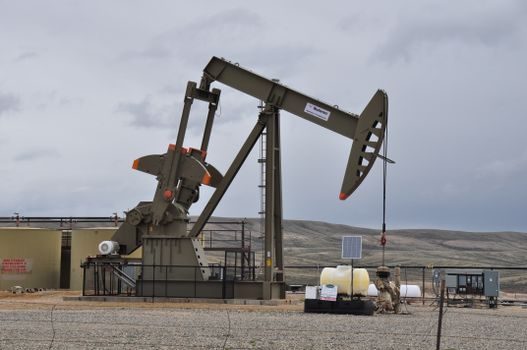
Plunger pumps sit in the positive-displacement (PD) family: a sealed plunger reciprocates inside a cylinder, displacing a fixed volume per stroke, so flow is set by stroke length × speed rather than impeller diameter × speed [S5, S9].
Operating Principle and Mechanical Footprint
Centrifugal pumps convert shaft torque into kinetic energy at the impeller eye, then convert that velocity head into pressure inside the volute; they tolerate continuous duty at a single Best Efficiency Point (BEP) and run with a continuously varying Q-H curve that drops as flow rises [S1].
Plunger pumps deliver a near-fixed flow per revolution regardless of discharge pressure up to the rated relief setting, which is why they are the workhorse for high-pressure cleaning, waterjet cutting, oil-field injection, and boiler-feed dosing where a centrifugal would simply stall or cavitate [S5].
Head, Flow, and Pressure Envelope
Single-stage end-suction centrifugal pumps typically top out around 90 m head on commodity builds, while the SS vertical submerged centrifugal in API 610 trim reaches capacities up to 450 m³/h and heads to 90 m at temperatures to 350 °F [S9].
Multistage centrifugal configurations push the envelope much higher — Modo Pump lists a horizontal multistage water pump at FOB US $550/piece with high-head capability for high-pressure transfer, and multistage sections are stacked to reach several hundred metres of head on a single shaft [S3].
Plunger pumps, by contrast, regularly deliver discharge pressures of 100–500 bar at flows of 1–50 m³/h, an order of magnitude above what a single-stage centrifugal can produce without exotic metallurgy and multi-section staging.
Fluid Compatibility and Material Options
Centrifugal pumps are specified across the full material matrix: cast iron for water, 304/316 stainless for chemical service, Alloy 20 and 904L for sulphuric and chloride-rich streams, and CD4MCu/duplex for FGD and brine [S9].
Plunger pumps add a sealing challenge that the centrifugal does not have at the wetted end: the plunger packing or chevron seal set is the wear part, and material upgrades (PTFE, graphite-impregnated, bronze) are chosen against the same corrosion tables that drive the centrifugal wetted-end pick [S9].
For slurries and solids-laden fluids, the centrifugal design shifts to open or vortex impellers with wider clearances; a horizontal slurry pump line in the same OEM family reaches 5000 m³/h on the largest double-suction split-case builds [S3].
Energy Efficiency and Throttling Behaviour
Centrifugal pumps follow an affinity law where power scales roughly with flow cubed at constant speed, so throttling a centrifugal with a downstream valve wastes power proportionally to the artificial head the valve burns [S2].
The right way to trim a centrifugal is speed control (VFD) or impeller trim, both of which drop part-load power close to the cube of the speed ratio and recover 20–40 % of the input on a typical throttled system [S2].
Plunger pumps maintain almost constant efficiency across the 30–100 % flow range because the displaced volume is mechanical, not hydrodynamic; their weakness is volumetric loss past worn plungers, which is why plunger users size for a small relief margin rather than a large throttling margin [S5].
Standards, API Compliance, and Sourcing

Process-grade centrifugal pumps in hydrocarbon service reference API 610, while marine and US-built units such as the Carver M Series carry the F998 close-coupled rating and the Maxum OH2 API 610 compliant end-suction line [S6].
SS vertical submerged centrifugal pumps are explicitly published to API 610 with capacities to 450 m³/h, heads to 90 m, and 304/316 stainless as the standard wetted material set [S9].
Self-priming farm irrigation centrifugal builds are typically claimed to ISO international standard for energy-saving design, paired with either electric motor or diesel engine drive [S10].
Selection Matrix: Centrifugal vs Plunger
Pick a centrifugal pump when the duty is high flow (tens to thousands of m³/h), low-to-moderate head (single-stage ≤ 90 m, multistage up to a few hundred metres), clean or slightly dirty fluid, continuous duty, and a tight $/flow capex ceiling [S1][S9].
Pick a plunger pump when the duty is high pressure (100+ bar), low-to-moderate flow (1–50 m³/h), viscous or shear-sensitive fluid, or the process needs a near-flat flow curve independent of discharge pressure [S5].
For high-pressure chemical injection and boiler-feed dosing where pulsing matters, a metering pump (a related PD class) often replaces the general-purpose plunger to hold ±1 % accuracy per stroke; a diaphragm pump covers the leak-free zero-emission duty that a packed plunger cannot [S5].
A gear pump or hydraulic pump enters the picture when the fluid is high-viscosity lube or hydraulic oil and the duty is steady positive displacement at moderate pressure, leaving the centrifugal and plunger to own the water and high-pressure process niches respectively [S1].
Failure Modes, NPSH, and Operating Limits
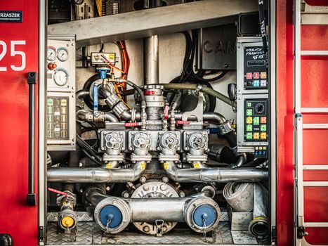
Centrifugal pumps fail most often from cavitation when available NPSH drops below the required NPSHR, from running far to the right of BEP (radial load, shaft deflection, seal damage), and from dry-running on mechanical seals [S1][S4].
The minimum continuous thermal flow for a centrifugal is non-zero; running below it causes the fluid to overheat in the casing and flash, which is why most API 610 builds carry a published minimum continuous flow (MCF) figure that operators must respect on partial-load service [S4].
Plunger pumps fail most often from packing wear, valve-seat erosion on the suction/discharge check, and plunger scoring from solids bypass; they tolerate deadheading briefly against a relief valve, which a centrifugal cannot do without tripping motor overload [S5].
Use Case Mapping
Municipal water transfer, cooling-tower circulation, fire-fighting ring main, and irrigation are the canonical centrifugal strongholds, with published models from 4-inch agricultural electric pumps to 5000 m³/h double-suction split-case units [S3].
High-pressure cleaning, waterjet cutting, oil-field mud pumping, and reverse-osmosis feed boosting are the plunger strongholds; downstream of these, smart positioner and solenoid valve selection also matters — for example pairing a solenoid vs diaphragm valve actuation speed decision map helps spec the on-off block on the discharge line.
When a chemical transfer is corrosive and the existing line uses a screw pump, the screw pump selection for corrosive chemical transfer spec map and the diaphragm vs inline pipeline pump calibration interval decision map are the cleaner references, but the centrifugal and plunger remain the two end-points of the high-flow / high-pressure trade-off [S1][S5].
Decision Snapshot
If the duty says “move 200 m³/h of cooling water at 30 m head, 24/7”, specify a centrifugal end-suction pump in cast iron with a 4-pole motor, expect 70–85 % BEP efficiency, and budget for a VFD if the load is variable [S1][S2][S9].
If the duty says “dose 5 m³/h of polymer at 80 bar into a slurry line”, specify a plunger pump with PTFE chevron packing, duplex wetted end, and a pulsation dampener, and skip any centrifugal that tries to “just do the job” with a smaller impeller and a PRV bleeding flow back to suction [S5].
The next trackable signal is Q3 2026 Chinese OEM FOB price action on multistage centrifugal builds (US $550/piece for the horizontal multistage benchmark) versus Q4 2026 lead times on API 610 vertical submerged builds [S3][S9].