Submersible sewage pumps are pulled to deck level on a guide-rail foot and lifting chain without breaking pipework, exposing the impeller and mechanical seal in under an hour. Magnetic drive pumps have no mechanical seal to replace, but any internal inspection requires the suction and discharge piping to be isolated, the can to be depressurized, and the back-pull-out to be removed — typically a full work shift of disassembly.
This comparison covers end-suction magnetic drive pumps in frame-mounted construction (API 685 class) and submersible solids-handling pumps in wet-well installations (EN 12255 class). Reciprocating dosing pumps, vertical turbine pumps, and progressive cavity pumps are outside the scope, even though they appear in adjacent services in chemical and wastewater plants.
Where each design is specified
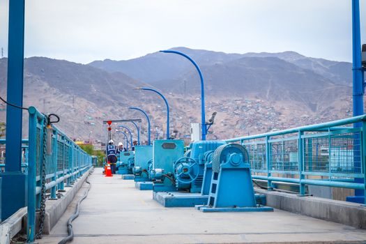
Submersible sewage pumps serve wastewater lift stations, stormwater sumps, and primary sludge transfer where the pumped fluid contains stringy solids, grit, and rags. Vortex, channel, and grinder impellers are standard options; free passage typically ranges 50-100 mm in municipal frames and 25-40 mm in compact grinder units. The pump is mounted on a guide-rail foot and auto-couples to a discharge elbow in the wet well; a single chain or hoist extracts the entire pump and motor assembly to deck level without entering the well.
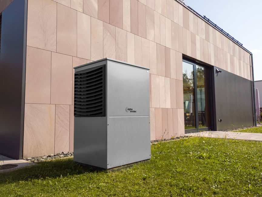
Magnetic drive pumps, also called sealless canned or coupled pumps, drive the impeller through a permanent-magnet or rare-earth torque ring separated from the wet end by a containment can. They are specified in chemical transfer, acid circulation, and hydrocarbon services where zero process leakage is mandatory and the pumped fluid is clean. Solid particle content above a few percent by mass is outside the design envelope; the can wall thickness sets a hard limit on erosion, and the inner magnet assembly cannot tolerate the impact loads that sewage service delivers. Reference specifications are ISO 5199 (centrifugal pump technical requirements) and API 685 (sealless centrifugal pumps for petroleum, chemical, and gas service).
Maintenance access architecture
The two designs have opposite maintenance philosophies. Submersible sewage pumps treat the wet end as a consumable; motors are routinely pulled, the impeller and mechanical seal are inspected, and the unit is dropped back in the well. The mechanical seal — a single faces-pair between oil chamber and impeller hub — is the most replaced part, and a typical failure cause is dry running from a low-level cutoff failure, a topic where pressure transmitter calibration and flow meter zero drift are the upstream failure contributors in mixed instrument rooms. A planned seal service in a municipal dry-weather lift station takes a two-person crew less than an hour per unit, including hoist, de-energization, and re-coupling.
Magnetic drive pumps treat the wet end as service-free between bearing and can inspections. There is no mechanical seal to replace; that single decision removes the highest-frequency maintenance task in a chemical pump. The penalty is that any internal inspection requires the suction and discharge piping to be drained, the isolation valves to be closed, and the can to be depressurized. Industrial valve selection matters here: specifiers prefer double-block-and-bleed ball valves or a single full-bore butterfly plus a drain port rather than a single line valve, because the magnetic drive pump has no internal leak path to confirm the line is isolated. A bearing and can inspection typically takes most of a work shift once the piping is isolated, the coupling is uncoupled, and the back-pull-out is removed.
Failure modes the maintenance plan must cover
Sewage pump failures concentrate in four areas: seal face scoring from grit ingestion, impeller vane erosion from sand, cable jacket damage from caustic vapour, and stator winding burnouts from repeated inrush. The wet-well environment is hostile, and the maintenance interval is usually yearly for a medium-duty unit and more frequent for a continuous-duty grinder. Dry running for more than a few minutes destroys the lower mechanical seal and frequently cracks the stator housing from the heat soak-back.
Magnetic drive pump failures concentrate in three areas: thrust bearing wear from the axial load of the magnet rotor, containment can fatigue at the welded seam, and magnet demagnetization if the rotor is stalled under full voltage. The first failure is detectable with vibration monitoring and is the most common reason a chemical plant schedules bearing service. The second failure is leak-only and usually prompts a process stream analysis, because the can material is the barrier between the pumped fluid and the atmosphere. The third failure is rare but catastrophic; it usually indicates that a PLC dry-run interlock has failed, because a magnetic drive pump should not be started against a closed discharge valve or an empty suction line.
Standards that govern the choice
ATEX 2014/34/EU and the IEC 60079 series apply to both pump types when installed in explosive atmospheres; the certification path differs for each design. Submersible sewage pumps in wet wells containing volatile vapours typically require Ex d or Ex db motors with surface temperature classes tied to the fluid flash point; the alternative is an Ex eb increased-safety motor in Zone 2 service. Magnetic drive pumps in flammable hydrocarbon service use the same equipment categories, but the containment can adds a separate approval path because it is a primary process boundary and not just a housing.
For material selection in sour hydrocarbon service, NACE MR0175 limits the hardness of wetted parts to prevent sulfide stress cracking; this often rules out standard 316 stainless steel fasteners on a magnetic drive pump and pushes the specification toward alloy 20, Hastelloy, or duplex grades. For general process pumps, ISO 5199 covers the mechanical and hydraulic test acceptance envelope, ISO 9906 sets the hydraulic performance grade (typically Grade 2B for process pumps), and API 685 covers the sealless magnetic drive variant with additional surge and partial-flow testing. Wastewater applications are not covered by API 685; the EN 12255 series covers pumping stations in municipal plants.
Decision criteria, lined up

The choice between a submersible sewage pump and a magnetic drive pump reduces to four questions: solids content, dry-run tolerance, leakage tolerance, and planned maintenance window. For a moderate-flow wastewater transfer at modest head, the service is solids-laden, intermittent, and the priority is rapid lift-out serviceability — submersible sewage pump. For a modest-flow hot acid circulation in a chemical plant, the service is clean, continuous, and the priority is no leakage — magnetic drive pump. Solids above a few percent and a continuous service profile push the answer toward sewage; clean, continuous, low-leakage service pushes it toward magnetic drive.
On maintenance metrics, a submersible sewage pump offers lift-out in under an hour, mechanical seal replacement in an hour or so per service, and bearing life in the multi-year range. A magnetic drive pump offers no seal but most of a work shift for an internal inspection, with bearing life in a longer interval. On energy and instrumentation, neither pump is inherently better; both benefit from pressure sensor and flow meter feedback to a PLC that interlocks the start permissive against a confirmed flow signal. On ATEX classification, submersible units in Zone 1 typically carry Ex db IIB T4 or T3 marking; magnetic drive units in Zone 1 carry the same motor marking plus a containment can approval, which adds paperwork at every site.
Real failure modes in service
A common case pattern: a magnetic drive pump on a long bearing service interval developed vibration readings indicating sleeve bearing wear, which would have caused a containment can contact and loss of barrier integrity had it continued. The repair required a full shift of pipework isolation and a spare bearing assembly. A parallel case in municipal lift stations: a submersible sewage pump on a yearly seal service had its seal replaced in less than an hour using the existing guide-rail hoist; no pipework was broken, and the cost was driven by labour and the seal kit rather than by downtime.
For sour hydrocarbon service on NACE MR0175-class fluids, magnetic drive pumps are increasingly specified because the can acts as a secondary process boundary and the absence of a packed or mechanical seal removes a common leak path. For abrasive sludge with a few percent dry solids, the can is the limiting feature and a magnetic drive pump is the wrong tool; the maintenance plan should expect an impeller and seal service more often on a submersible sewage pump, and the discharge piping should be designed for rapid uncoupling. The rule stamped on most magnetic drive pump data sheets and vendor manuals is: "Do not run the pump dry. Damage to the thrust bearings or the can will occur within minutes." This is why the PLC dry-run interlock is the most important instrumented safeguard in any magnetic drive circuit.
Track these signals before specifying: confirm whether the process fluid contains more than a small amount of suspended solids, check the flow meter installation for a minimum flow path that the magnetic drive can prove, and verify whether the PLC dry-run interlock is wired through a hard-wired contactor rather than a software flag — the latter is the most common cause of magnet demagnetization reported by pump repair shops over the past decade.