
MCCs are typically justified when a project carries a significant number of across-the-line motor starters; standalone starters rarely beat a centralized MCC past roughly 6-10 motor buckets on a single bus, and the global motor control centers market is forecast to grow from USD 4.6 billion in 2020 to USD 6.3 billion by 2025 at a 6.4% CAGR [S3][S5].
A motor control center is a factory-assembled, common-bus enclosure combining starters, feeder disconnects, lighting panels, interlock relays, and metering in one lineup — a definition the Sogou encyclopedia entry reinforces as a single power-distribution and instrumentation hub [S2]. Selection below is structured as a 2026 spec map for process engineers, plant electrical leads, and EPC procurement.
Define the duty before picking a topology
The first hard filter is voltage class: low-voltage MCCs serve motors up to 600 V (typically 208/240/480/600 V at 50/60 Hz, horizontal bus 600-1600 A short-circuit rated), while medium-voltage MCCs handle 2.3-13.8 kV drives and large induction motors above ~250-300 kW [S2][S3]. Pick LV unless the largest motor exceeds ~200 hp (150 kW) at 480 V or harmonic/soft-start requirements demand MV switchgear with vacuum contactors.
Type choice splits along an intelligent vs conventional line: conventional (electromagnetic) sections remain the lowest-capex fit for fixed-speed across-the-line duty, while intelligent MCCs integrate motor-protection relays, Ethernet/Modbus TCP or PROFIBUS gateways, and energy metering on a per-bucket basis [S5]. A buyer running mostly VFD-driven conveyors and pumps should default to intelligent; a buyer running standard induction motor starters in a non-networked facility can save 20-30% on capex by staying conventional.
Five non-negotiable selection criteria
1) Short-circuit withstand rating (kA Icw / kAIC) — LV sections must be rated at least 65 kAIC at 480 V for industrial plants with transformer secondaries ≥1500 kVA; underspec'd bus bracing is the most common MCC field-failure root cause. 2) Enclosure rating — NEMA 1 (indoor, dry), NEMA 3R (outdoor, rain), NEMA 4/4X (washdown, with 4X adding stainless or non-metallic for corrosive sites), and NEMA 12 (dust, drip). 3) Bus bracing material — copper main bus is standard; tin-plated or silver-plated copper is required for harsh-ambient sites per most UL 845 / IEC 61439-1 builds. 4) Starter type — across-the-line, soft-starter, or VFD bucket, with overload relay class (10, 20, 30) matching motor thermal curve. 5) Communication bus — Modbus RTU/TCP, PROFIBUS, EtherNet/IP, or PROFINET depending on the SCADA layer upstream. [S3]
The VA 26 24 19-2010 spec template explicitly ties MCCs to companion sections including Section 26 05 71 (Electrical System Protective Device Study) and Section 26 29 11 (Motor Starters), confirming that protective-device coordination, not bucket count alone, drives a defensible MCC package [S3]. On a related note, an AC motor spec must freeze before the MCC schedule; matching motor FLA, service factor, and locked-rotor code (NEMA A/B/C/D) to overload class is non-negotiable.
Conventional vs intelligent: criteria-based comparison

On a 480 V, 1000 A main bus, 12-bucket build, the realistic options line up against four decision criteria as follows. Conventional (electromagnetic contactor + bimetal or solid-state overload): capex baseline 1.0x, communication none or Modbus RTU only, metering per-line CTs optional, retrofit simplicity high. Intelligent (electronic motor-protection relay + bus gateway): capex 1.4-1.7x, communication Ethernet/PROFINET/EtherNet-IP native, metering kWh + power quality per bucket, retrofit complexity medium. Draw-out intelligent: capex 1.7-2.1x, communication same, hot-swap buckets without bus shutdown, retrofit complexity low for live plants. [S3]
Conventional wins on capex and on simple, infrequent-duty plants; intelligent wins on energy reporting, predictive maintenance, and integration with the plant control cable and network layer. The MarketsandMarkets 2020-2025 forecast places intelligent MCCs as the faster-growing segment, with conventional MCCs still holding the larger installed-base share at the 2020 USD 4.6 B baseline [S5].
Who should NOT pick a low-voltage conventional MCC
Three duty profiles break a conventional LV build. First, soft-stop or controlled-acceleration duty on high-inertia loads (centrifuges, large fans) needs soft-starter or VFD buckets, not across-the-line contactors. Second, hazardous-area sites (Class I Div 2 or Zone 2) require purged or increased-safety enclosures per IEC 60079-series; a standard NEMA 1 cabinet is unsafe and non-compliant. Third, plants chasing ISO 50001 energy reporting need per-bucket kWh metering that only intelligent or draw-out intelligent sections deliver cost-effectively. [S5]
For hazardous-area retrofits the spec map shifts to a different cabinet family; the Brownfield PLC Upgrade: Ex Control Station Selection Criteria page covers the upstream Ex I/O problem in detail. A typical LV MCC in a Class I Div 2 area also pairs with Ex-rated motor terminators; if your drive train includes gear reducers, the Cycloidal Reducer Selection Criteria for Conveyor Drive Trains reference helps size the mechanical side to the electrical-side starting torque.
Standards, coordination, and the spec checklist

Anchor every MCC package to a master spec. VA 26 24 19-2010 defines a workable template: submittals must include catalog data, shop drawings, and per-motor overload-relay settings; seismic restraint (Section 13 05 41), advanced utility metering (Section 25 10 10), and protective-device study (Section 26 05 71) are listed as required related work [S3]. For LV equipment the governing product standard is UL 845 in the US and IEC 61439-1/-2 in the EU; for MV the relevant assembly standards are IEC 62271-200 and IEEE C37.20.7 (arc-resistant). Coordination upstream/downstream calls for a short-circuit study (kAIC) and a protective-device time-current-curve plot before any bus is ordered.
Site acceptance should bundle the four manual sets required by the VA spec — operating, maintenance, testing, and "as-installed" wiring diagrams — plus overload-relay settings and replacement-part ordering information [S3]. Seismic certification (per VA Handbook H-18-8) is required in seismically active regions; in California, Japan, or high-Seismic-Zone installations, the bus bracing and anchorage must be matched to the IBC site class [S3].
Field-failure modes and limits to remember
Conventional MCC sections are intolerant of bus modification while energized; even with a main breaker open, the line-side bus remains live. Draw-out intelligent sections solve this but cost 1.7-2.1x the capex [S5]. Dust and moisture ingress is the most common NEMA 1 indoor failure; specifying NEMA 12 with gasketed doors and thermostatically controlled space heaters in humid climates is cheap insurance. Harmonic distortion on VFD-busy MCCs accelerates capacitor and insulation aging; a 5% line reactor or active harmonic filter upstream is standard practice for VFD-heavy lineups.
Another limit: a single-bucket fault in a non-draw-out lineup typically forces a multi-hour shutdown while the bucket is bypassed. For processes with high availability targets (≥99.5%), draw-out intelligent sections with hot-swap starters pay back in two to three avoided downtime events. Finally, communication-layer mistakes are common — Modbus RTU daisy-chains are not the same physical layer as Ethernet/PROFINET; bucket-level gateways must be specified per protocol, not field-retrofitted.
Shortlist logic for 2026 buyers
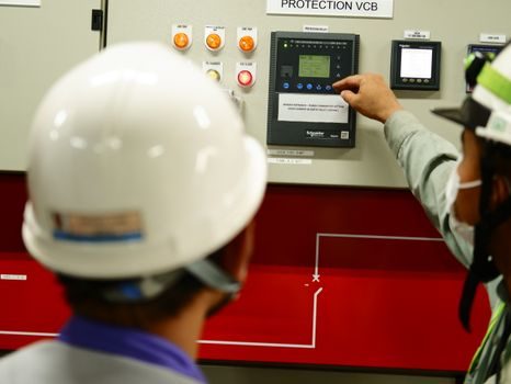
Start with the voltage class decision, then bucket count, then starter duty profile, then communication/control, then enclosure. The shortlist reduces to three realistic buckets: (1) conventional LV with across-the-line starters and Modbus RTU for fixed-speed, non-networked facilities; (2) intelligent LV with electronic motor-protection relays and PROFINET/EtherNet/IP for energy-reporting plants; (3) MV at 2.3-13.8 kV with vacuum contactors for drives above ~300 kW. Lock the protective-device study and seismic class before RFQ release, and verify short-circuit withstand against the actual transformer impedance, not the rule-of-thumb kAIC value. [S3]
Trackable signals: confirm whether the OEM publishes a published kAIC value at 480 V, 65 kA minimum; demand an internal arc-tested assembly per IEEE C37.20.7 for operator safety on LV/MV builds ≥65 kAIC; and require four complete manual sets (operating, maintenance, testing, as-installed) with overload-relay settings per VA 26 24 19 Section 1.4D [S3]. A spec that passes those three filters is generally defensible at FAT and at field commissioning.
Detailed specification references: access control.