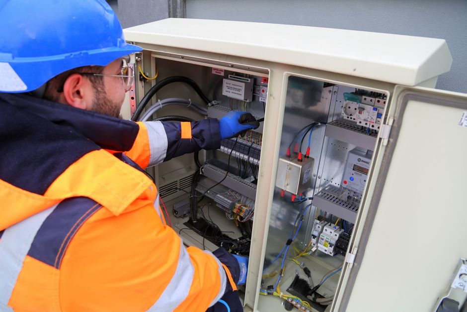
Motor protection relays sit between the contactor and the motor, and the right pick is dictated first by three numbers — motor rating, supply type, and trip class — not by brand or display colour [S1].
Industrial three-phase induction motors above 250 HP are normally supplied at high voltage to keep operating current and frame size manageable, which is why high-voltage induction motor protection is its own product category rather than a scaled-up low-voltage relay [S3].
What a motor protection relay must cover
The relay's job is to detect abnormal electrical or mechanical conditions, trip the contactor, and keep the fault from propagating back into the supply network — covering thermal stress on the winding, single phasing, earth fault, short circuit, locked rotor, excessive hot starts, and bearing failure [S1][S3].
For a low-voltage motor in a benign panel, a thermal overload relay sized to the motor's full-load current handles most of those cases; for a high-voltage induction motor the relay additionally has to discriminate between inrush and locked-rotor current, which can sit at 5–7× FLC for several seconds, so a simple bi-metallic strip will not do [S3].
Digital numerical relays add functions that electromechanical units cannot deliver cleanly: acceleration time, number of cold/hot starts per hour, time-between-starts lockout, and a thermal model that uses both current and RTD/PTC inputs to mirror winding temperature [S1][S4].
Selection gates: rating, supply, trip class, environment
Gate 1 is the motor's full-load current and locked-rotor current at the actual supply voltage — the relay's current range must bracket FLC with a 1.1–1.3× service factor margin, and its short-circuit element must coordinate with the upstream fuse or breaker [S1][S3].
Gate 2 is the supply system: three-phase voltage level, grounding method (solidly grounded, resistance grounded, or impedance grounded), and available fault level — single-phase and earth-fault elements are tuned to the system's zero-sequence impedance, and a relay sized for a 400 V solidly grounded system will miscoordinate on a 6.6 kV resistance-grounded one [S3].
Gate 3 is trip class — Class 10 for standard submersible and normal-load motors, Class 20 for high-inertia fans and conveyors, Class 30 for very high-inertia loads like crushers, and special classes above that for extra-heavy starting; choosing a class slower than the motor can tolerate is a direct path to winding failure on stalled starts [S1][S3].
Gate 4 is the operating environment: hazardous-area motors carrying ATEX/IECEx certification must be paired with a thermistor relay that reads PTC sensors embedded in the windings, because surface-mounted sensing on the frame will not reflect the true hotspot temperature that the hazardous-area certification is built around [S2].
Thermal overload vs thermistor vs multifunction digital

A bi-metallic thermal overload relay is the cheapest option and is adequate for non-critical LV motors up to roughly 100 A with benign starts; it is essentially a current-to-heat analogue and cannot tell the difference between a slow overload and a stalled rotor once the strip has heated [S3].
A thermistor motor protection relay such as the ABB CM-MSx range reads PTC sensors cast into the motor windings, so it measures the actual hotspot temperature rather than inferring it from line current — a clear advantage when the motor is in a hazardous area, or when the duty cycle includes frequent starts, jogging, or low-voltage operation that biases the thermal model [S2].
A multifunction numerical motor protection relay — for example the SEL-710-5, which lists enhanced thermal modelling, locked-rotor start protection, time-between-starts lockout, and optional incipient-fault plus vibration monitoring on its datasheet — covers every electrical fault class plus thermal, and adds communications (Modbus, IEC 61850, DNP3) for SCADA integration, but the per-unit cost sits an order of magnitude above a thermal overload [S4].
Who a thermistor relay is — and is not — for
Spec a thermistor motor protection relay when the motor either has ATEX/IECEx marking, runs a high number of starts per hour, or is mechanically coupled to a load where the conventional thermal model breaks down — variable-frequency drives, submersible pumps with constrained cooling, and motors in ambient temperatures above 40 °C [S2].
Do not pick a thermistor-only relay as the sole protection on a high-voltage induction motor: PTC sensing covers winding overtemperature but leaves out single-phasing, earth fault, short circuit, and locked-rotor current-based protection, all of which need current transformers and a numerical relay to detect and discriminate properly [S3].
On large HT motors, a multifunction digital relay handles the current-based protections while accepting PTC/RTD inputs as a separate winding-temperature channel — the two sensing paths are complementary, not alternatives, and overloading a single thermistor relay with HT-grade fault duties is one of the more common spec errors seen on retrofit jobs [S1][S3].
Standards, wiring, and coordination that decide the buy

For hazardous-area motors, the relay's certification must match the motor's zone and protection type — pairing an ATEX-rated motor with a non-ATEX thermistor relay is a documentation failure even if the PTC wiring is correct, because the safety case relies on the certified controlgear as well as the certified machine [S2].
Coordination with upstream short-circuit protection is a separate problem: the relay's instantaneous or short-time element must be set above the motor's locked-rotor current at the worst-case supply voltage but below the upstream fuse's minimum melt or the breaker's instantaneous trip, otherwise the relay will never see a short-circuit fault and the breaker will clear first [S1][S3].
Wiring rules that decide installation cost include whether the relay accepts ring-type CTs for retrofit into an existing panel, whether the PTC input is intrinsically safe for hazardous-area motors, and whether the unit supports draw-out construction so a faulty relay can be swapped without disturbing line-side wiring [S1][S4].
Spec checklist before you sign the PO
1) Motor FLC and locked-rotor current at the actual supply voltage, with a 1.1–1.3× service margin. 2) System voltage and grounding method. 3) Trip class matched to the load's starting inertia. 4) Hazardous-area classification of the motor and matching relay certification. 5) Required number of starts per hour and any time-between-starts lockout. 6) SCADA protocol required (Modbus, IEC 61850, DNP3). 7) Coordination study with the upstream fuse or breaker, including the available fault level at the motor terminals [S1][S3][S4].
Items 1–4 fix the relay family; items 5–7 then pick the variant within that family, and the price gap between a base thermal overload and a fully-loaded HT numerical relay is large enough that the right answer is usually one step above the minimum, not three steps above.
For a broader selection framework, the electrical fire monitor versus motor protection relay spec map shows where the two device classes overlap and where they do not, and a related look at how to choose a solenoid valve for 2026 applies a similar rating-and-duty filter to a different component family.
For the relevant spec sheets and selection criteria, see motor protection relay, microcomputer protection, and industrial relay.