The governing decision in a pneumatic conveying system spec is the combination of material bulk density, particle size, conveying distance, and required tonnage — these four values alone fix whether the line runs dilute-phase at high velocity or dense-phase at low velocity, and whether it is built as a positive-pressure, vacuum, or combination unit.
Pneumatic conveying moves dry bulk solids in a gas stream through enclosed piping and is the standard transport method in chemical, pharmaceutical, food, plastic, mineral and cement plants where dust-tight, multi-direction routing matters more than lowest energy per ton [S1]. Selection work, not component picking, is where most projects either save 15-30% on installed cost or pay for it in line blockages.
Phase regime: dilute vs dense vs semi-dense
Dilute-phase conveying operates at solids-to-air loading ratios typically below 15:1 by weight and at air velocities of 15-30 m/s, with the product fully suspended; it suits non-fragile, granular, free-flowing materials at moderate distances up to a few hundred metres [S1][S2]. Dense-phase conveying runs at loading ratios above 30:1 and at much lower line velocities — sometimes below 5 m/s for very fine or cohesive powders — and is selected when the material is abrasive, friable, or when pipe wear and particle degradation are primary concerns [S1]. Semi-dense or mid-dense phase sits between the two and is common where plants need a compromise between energy and gentleness.
A first-pass rule of thumb used by EPC specifiers: heavy, coarse, free-flowing granules (e.g. plastic pellets, sand, alumina) almost always end up dilute-phase; fine, cohesive, or fluidisable powders (e.g. cement, fly ash, flour, toner, PFA) usually end up dense-phase. Particle size below roughly 100 µm combined with bulk density under 800 kg/m³ is a strong dense-phase indicator [S1].
Pressure mode: positive-pressure, vacuum, or combination
Positive-pressure (pressure-vessel) systems use a blower or compressor above atmospheric to push material through the line; they handle the longest distances, the highest capacities (often 50-100 t/h per line in cement and mineral service), and multiple pickup points feeding a single destination [S1][S2]. Vacuum systems pull material with suction below atmospheric, cap at shorter distances — typically 50-100 m — but excel at multi-source pickup from several hoppers, silos, or railcars into one receiver, with inherent dust containment [S2].
Combination systems (vacuum pickup, pressure delivery) bridge the two: vacuum trucks or stationary vacuum units collect from several points, drop into a rotary valve or blow tank, then a pressure leg pushes to the destination silo. This is the default architecture for pharmaceutical, food and additive plants where flexibility and clean discharge outweigh raw throughput [S2]. For an existing gravity-fed material-handling line where the specifier is also weighing belt alternatives, the roller conveyor vs bucket elevator comparison covers the load-class crossover where pneumatic starts to lose on energy cost.
Material properties that decide the line
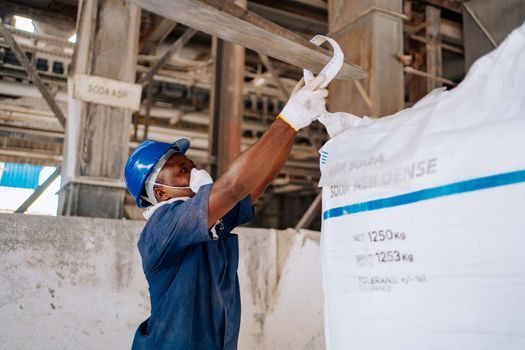
Four material values are non-negotiable inputs on a pneumatic conveying datasheet: bulk density (kg/m³), particle size distribution with d50 and top-cut, moisture content, and a degradation or attrition limit [S1]. Hygroscopic or sticky materials shift the design toward dehumidified air, vibratory aeration pads on the hopper, and lean-phase with defluidisation prevention.
Corrosive or reactive powders add material constraints upstream of the conveying spec: stainless or aluminium conveying lines for food/pharma, conductive hose and grounding for combustible dusts handled under ATEX 2014/34/EU or IEC 60079-series zoning [S1]. Where the powder is combustible (many plastics, flours, sugars, metal fines), the spec must integrate explosion protection — rupture panels, flameless venting, isolation valves — sized to the vessel KSt and Pmax values from dust explosibility testing.
System components: blower, feeder, line, separator
The four sub-assemblies that scale with the conveying spec are the air-mover (positive-displacement blower, vacuum pump, or screw compressor), the feeder (rotary valve, blow tank, venturi eductor, or screw feeder), the conveying line (aluminium, carbon steel, stainless, or lined), and the receiving separator (cyclone, filter receiver, or silo with top-mount filter) [S1][S3]. Rotary valves set the throughput ceiling on pressure systems — common industrial sizes run 4-20 L/rev and 10-100 rpm, giving a usable range from a few hundred kg/h up to ~30 t/h per valve cluster. Blow tanks unlock the high-tonnage, long-distance end of the range by pulsing slugs of material at low velocity [S2].
Receiver sizing, filter area, and rotary airlock or blow-tank capacity are the three numbers an EPC will lock first because the rest of the line bends to fit. For plants also handling finished-goods storage downstream, the IBC tank sourcing guide covers the UN-rated container spec that often sits at the receiving end of a pneumatic line in chemical and food plants.
Energy, wear, and operating-cost levers
Energy per ton conveyed is the single biggest operating-cost lever; dilute-phase vacuum systems on short runs can sit around 1-3 kWh per ton of product, while long-distance, high-pressure dilute lines on cement or minerals can climb above 15-20 kWh/t [S2]. Dense-phase with high loading ratios typically halves the air requirement and therefore the blower power for the same tonnage, but the trade is higher capital for blow tanks, booster stations, and instrumentation. Plant air, instrument air, and dryer capacity must be specified together — pushing more air is not a free upgrade.
Wear is the second cost lever: each 90° bend in a dilute-phase line at 25 m/s handling 200 µm alumina is a consumable. Particle attrition — breakage of granules, fracturing of catalyst beads — sets hard upper limits on velocity for fragile products; this is where dense-phase, low-velocity designs pay back through reduced fines generation and lower filtration load [S1].
Selection criteria checklist and decision matrix
A defensible pneumatic conveying spec answers, in order: material properties (density, PSD, moisture, abrasiveness, explosibility), required capacity (t/h or kg/h), conveying distance and routing (number of bends, vertical lift, multi-point), phase preference driven by the first two, pressure mode (positive, vacuum, or combined), and the air-mover and feeder sizes that satisfy the rest [S1][S2]. Each of these has hard engineering limits — for example, dilute-phase vacuum lines drop off in capacity above ~100 m equivalent length, and rotary-valve sealed systems lose efficiency at differential pressures above ~1 bar g.
Compared against the four decision criteria, the three operating modes split as follows. Positive-pressure dilute-phase wins on distance (multi-hundred-metre runs) and capacity (50-100+ t/h) but loses on multi-source flexibility. Vacuum dilute-phase wins on multi-point pickup and inherent dust containment but loses on distance and maximum tonnage. Dense-phase positive-pressure wins on low particle degradation and energy per ton on long runs but loses on capex and on materials that do not fluidise. For plants considering enclosed mechanical alternatives where the material is unit-load rather than bulk, the roller conveyor vs bucket elevator spec breakdown is the useful counter-reference. Where the wider handling chain also involves elevated-temperature or cast-metal components upstream, the gravity die casting machine selection guide sits in the same specifying discipline: match the alloy and tonnage class first, the rest of the line follows.
Limitations and failure modes
The five recurring failure modes on pneumatic conveying lines are saltation (particles dropping out of the gas stream), line plugging at bends or hoppers, excessive product degradation, filter blinding at the receiver, and wear-through at elbows [S1]. Saltation is solved by raising velocity or switching to dense-phase; plugging at bends is solved by enlarging the bend radius, reducing the number of bends, or going to a non-erasive dense-phase pulse. Receiver filter blinding is solved by correct filter area sizing (typical rule 0.5-1.0 m² filter area per 100 m³/h of conveying air, material-dependent), online pulse cleaning, and antistatic filter media for combustible dusts.
Pneumatic conveying is the wrong tool when the material is wet, sticky, or chunky above ~25 mm, when the routing is mostly horizontal over very long distances where energy per ton becomes uneconomic, or when the product is so fragile that even dense-phase pulses break it. For those cases, mechanical conveyors — belt, chain, bucket, screw — take over, and the mesh belt vs belt conveyor spec cut covers the temperature-and-load crossover where mechanical lines are preferred.
Sourcing and standards
Specifiers should anchor the design to the governing references: ATEX 2014/34/EU and the IEC 60079 series for equipment in zoned areas, ISO 7145 for pneumatic-conveying line hydraulics where applicable, and ASME B31.3 for pressure-piping design on pressure systems [S1]. For combustible dusts, the design integrates NFPA 654 / NFPA 68 dust-explosion safeguarding on the receiver and filter, and material-test data (KSt, Pmax, MEC) from ISO/IEC dust-explosion test methods. For food and pharmaceutical service, the spec extends to 3-A, EHEDG, or FDA-grade contact surfaces, polished stainless lines, and CIP-capable filter receivers.
The trackable next nodes for a specifier in 2026: lock the four material values and the t/h, decide phase and pressure mode, then size the blower and feeder from manufacturer selection software — most major OEM sizing tools ([S3]-type vendor portals) accept the same four inputs and output a line diameter, air volume, pressure profile, and kW figure that can be cross-checked between vendors. The signal to watch is dense-phase adoption in mid-range applications (10-30 t/h at 100-300 m): as blow-tank and booster control systems fall in price, the energy argument is pulling more dilute-phase pressure lines toward dense-phase retrofits.
For component-level specifications, see pneumatic actuator, pneumatic conveyor, and pneumatic cylinder.