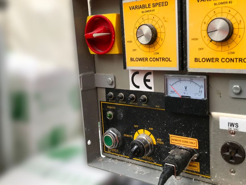
Inside an MCC (Motor Control Center) enclosure, the pneumatic tubing run is short, mostly fixed, and lives next to switching contactors, VFDs, and control wiring — so the spec is driven less by flexibility and more by pressure rating, oil resistance, and electromagnetic/condensate compatibility [S3][S6].
Common MCC pneumatic circuits feed pilot air to solenoid valves, operate small pneumatic actuators on starter interlocks, and supply purge air to panel enclosures. The control-air branch typically runs 1/8-in. to 3/8-in. OD, while the main supply branch sits in the 1/4-in. to 1/2-in. OD range, and OD/English units must not be mixed on the same machine [S5].
Material Decision: Nylon 12 vs. PU vs. PTFE
Three polymers cover roughly 90% of MCC-pane pneumatic runs: Nylon 12 (PA12), Polyurethane (PU), and PTFE — each with a distinct spec signature that maps to a specific duty inside the cabinet [S4].
For fixed or semi-fixed control-air lines that sit clamped to the panel back-plate, Nylon 12 is the default: low moisture absorption, stable dimensions, and good UV/aging resistance. For dynamic runs that flex with a hinged door or moving cassette (draw-out MCC buckets), specify PU for its fatigue life — but verify oil-mist compatibility, since standard ester-based PU will swell in petroleum-oil-lubricated air [S3][S4]. PTFE is reserved for high-temperature zones near VFD heat sinks or where chemical resistance is required [S4].
Pressure Rating and the 4:1 Safety Factor
Manufacturers measure thermoplastic tubing burst pressure at 75°F (23.9°C) and derate it by a safety factor — typically 3:1 to 4:1 depending on application severity [S6].
The arithmetic is direct: a 450 psi burst at 75°F gives 112 psi working pressure at a 4:1 factor; a 3:1 factor on the same tube yields 150 psi working. For MCC pilot-air circuits that normally operate at 80–100 psi (5.5–6.9 bar), the tube should carry a working pressure rating of at least 150 psi after derating [S6]. Pressure derating also tracks temperature — working pressure drops as temperature climbs, so a tube rated 150 psi at 75°F may only carry ~60–70% of that value at 140°F inside a hot MCC cabinet [S6].
Temperature, Condensate, and Oil Mist Inside the Cabinet
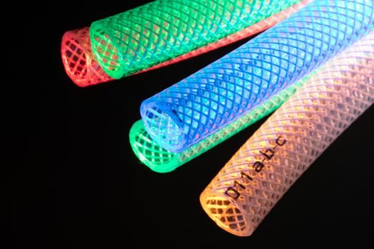
MCC enclosures generate internal heat from contactor coils, bus bars, and VFD switching losses; panel-internal temperatures commonly reach 113–140°F (45–60°C) in summer-loaded cabinets, which directly impacts tubing selection [S3].
Three environmental factors must be checked against the tube data sheet: (1) high-temperature derating of working pressure, (2) oil-mist compatibility for plants using oil-flooded compressors, and (3) condensate drainage — Nylon 12 has low moisture absorption, while LDPE and standard PU absorb more water and may need upstream FRL drying [S3][S4]. For high-temperature zones near VFD heat-sink panels, specify fluoropolymer (PTFE) tubing; it carries the broadest temperature window of the common polymers [S4].
Size, Routing, and Separation from Power Conductors
Tube sizing is specified by outside diameter, and most MCC pneumatic runs sit under 1/2-in. OD — with 1/4-in. and 3/8-in. dominating control-air branches and 1/8-in. used only for short pilot signal lines to a single valve manifold [S5].
Routing rules worth pinning to the drawing: (a) keep pneumatic lines at least 50–100 mm parallel-separation from VFD output power cables to avoid conducted-noise pickup on shared cable trays; (b) use push-in fittings on Nylon 12 and PU for fast field service inside draw-out cassettes; (c) anchor fixed runs with P-clips every 300–500 mm to prevent vibration-induced fatigue at fitting barb seats; and (d) provide a dedicated air-preparation manifold (filter + regulator + lubricator) sized to the panel's total Cv, not to a single branch [S1][S3].
Compliance and Documentation

For MCC projects delivered into regulated sites (utilities, oil & gas, pharmaceuticals), the tube data sheet must list RoHS compliance at minimum, and FDA / NSF 51 for food-grade MCC rooms — Nylon 12, PU, and PTFE all carry RoHS markings, with NSF-51 lines available on selected Nylon 12 and PTFE grades [S4].
For hazardous-area MCC builds (Class I Div 2 / Zone 2), confirm that the tube itself meets the non-electrical component requirements and that the enclosure purge system uses tubing compatible with the protective gas — this overlaps with broader hazardous-area skid valve selection logic, where every seal and tube in the pilot-air path must be traceable to the area classification. Where the panel needs rapid pneumatic diagnostics, the choice between an FRL diagnostic port and a push-in diagnostic pneumatic fitting is covered separately in FRL vs push-in diagnostic comparisons [S7].
Who Should NOT Pick the Default Nylon 12
Nylon 12 is the wrong default in three MCC scenarios: (1) panels mounted on vibrating machinery where PU's fatigue life wins; (2) cabinets routed through cold-aisle / outdoor sections where low-temperature flexibility is required — PU retains flexibility below -40°C better than Nylon 12; and (3) any run carrying hot air above 80°C continuously, where PTFE's thermal ceiling is required [S3][S4].
If the MCC controls actuators that need vacuum generation for pick-and-place, the upstream tube spec ties back to the vacuum generator sizing calculation — undersized tubes starve the generator and collapse working flow. Also note that if the pneumatic run feeds an MCC cabinet door-interlock cylinder, the dynamic duty may justify stepping up from Nylon 12 to PU even on a short run [S3].
Selection Shortlist for MCC Pneumatic Tubing

Match material to duty in one pass: fixed control-air run (clamped, oil-mist-free) → Nylon 12, 1/4-in. OD, 4:1 safety factor; hinged door or draw-out bucket run → PU, 1/4-in. OD, oil-resistant grade; high-temperature zone near VFDs → PTFE, 1/4-in. OD, verify pressure derating; long main supply inside the panel → Nylon 12, 3/8-in. OD; vacuum generator feed → 3/8-in. PU or Nylon 12 sized to generator Cv [S3][S4][S5][S6].
Track two signals on every MCC pneumatic drawing: the tube material + OD/ID callout against the data sheet working-pressure curve at the panel's worst-case internal temperature, and a one-line note confirming RoHS / FDA / NSF status for the project specification. Where the pneumatic circuit feeds pneumatic cylinders on the MCC structure, the tube run length should also be rechecked against cylinder cycle rate, since long small-bore tubes add dead volume that slows response on fast-acting valves [S5].
