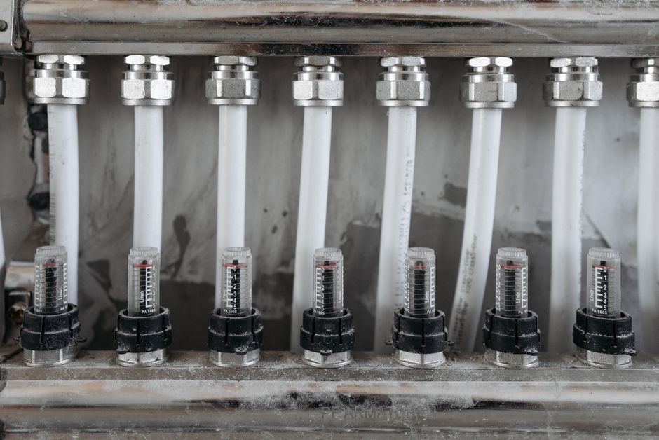
On a plant floor with variable-frequency drives, welding inverters, or walkie-talkie traffic, the pneumatic cylinder is mechanically and electrically inert — its only electrical path is a reed or magnetic-piston sensor drawing milliamps at 24 VDC, which is naturally resilient to conducted and radiated EMI [S3].
By contrast, the FRL unit has become an electronic subsystem: closed-loop pressure transducers, I/O-link or IO-Link-compatible regulators, digital gauges, and condensate drains with solenoid valves — every one of which is a potential EMC failure node per ISO 4414 and IEC 61000-6-2 generic immunity expectations for industrial equipment.
Why the cylinder is the easy side of the EMC story
A standard ISO 6432 / VDMA 24562 double-acting pneumatic cylinder like the PHD Series CV has anodized aluminum heads, caps, and tube, a PTFE wear ring, and a stainless tie-rod assembly — no active silicon inside the bore [S3]. When the only feedback is a reed switch, the wiring harness is a single twisted pair terminated in a transistor output, typically rated for 10–30 VDC at ≤100 mA; the magnetic field it switches is generated by a permanent magnet in the piston, so there is nothing to radiate, modulate, or mis-trigger under RF stress [S3].
That immunity is why automotive body shops, robotic welding lines, and tire-curing presses keep specifying ISO pneumatic cylinders rather than swapping to electric actuators near 100 A inverter switching: the actuator itself never goes into fault. The same logic explains the AUTOMAX TMASD clamp cylinder being specified for swiveling-flange clamping with 26 mm, 27 mm, and 29 mm strokes — these are clamping loads, not data-acquisition nodes [S1]. For a process engineer, the practical takeaway is: never blame the cylinder for an EMC trip; trace the wiring from its sensor and the valve coil on its directional valve instead.
Where the FRL package actually picks up EMC risk
An FRL train in 2026 is rarely just a polycarbonate bowl, a diaphragm regulator, and a drip-style lubricator. Each of those is a printed-circuit assembly with microcontroller, switching power supply, and I/O transceivers sitting on a 24 VDC rail that is shared with the rest of the cabinet — and that rail is the #1 antenna for conducted RF from adjacent VFDs.
The failure modes are well known in the field: digital pressure readouts that flicker or latch high under a 10 V/m RF sweep, proportional regulators that drift the regulated pressure by ±0.1–0.3 bar during a VFD shoot-through, solenoid coils on auto-drains that buzz at half-stroke. The fix is structural, not component-level: keep the FRL on a dedicated 24 VDC branch fed through a DIN-rail EMC filter, route its signal cables in shielded twisted pair with the shield grounded at the cabinet entry only, and maintain 200 mm (or one cable-tray divider) of physical separation from VFD output cables. The 2025–2026 modular FRL catalogs from Asia-Pacific suppliers have responded by offering metal-bodied regulators with IP65 encapsulators and IO-Link interfaces, which centralize the digital traffic on one M12 cordset and remove parallel analog runs that act as patch antennas [S2][S5][S6].
Decision matrix: when to harden the cylinder side vs the FRL side
Use this four-criterion comparison to allocate the EMC budget on a new pneumatic build: [S5]
• Radiated immunity (EN 61000-4-3, 80 MHz–6 GHz, 10 V/m): Cylinder with reed switch — no active electronics, expected pass without mitigation [S3]. FRL with electronic regulator — typically requires shielded cable + ferrites, budget 30–60 engineering hours. • Conducted immunity (EN 61000-4-6, 150 kHz–80 MHz, 10 Vrms): Cylinder wiring — single twisted pair to sensor, generally robust. FRL 24 VDC bus — requires filter (e.g., Schaffner FN 2070 class) at cabinet entry. • Surge/burst (EN 61000-4-4 / -5): Cylinder solenoid valve coil — fit a varistor or TVS across the coil (e.g., 30 V rated for 24 VDC). FRL electronics — add a combined TVS + PTC on the supply. • Field-replaceability under EMC fault: A standard ISO pneumatic cylinder swap is a 10-minute wrench job [S3]; an FRL regulator swap requires recalibration against a reference gauge and PLC re-mapping of the IO-Link device description.
The matrix makes the answer concrete: a Tier-1 automotive welding line with 600 robots and 2,400 cylinders per shift should still treat the FRL cabinets — typically one per cell, mounted 3–5 m from the robot controllers — as the EMC-critical subsystem, not the actuators.
Selection criteria for EMC-robust FRL packages
When the FRL has to live in an electrically hostile zone, the spec checklist is short and concrete. Demand an EN 61000-6-2 declaration of conformity from the FRL manufacturer, not just a generic CE mark — EN 61000-6-2 is the industrial generic immunity standard covering 10 V/m RF and 2 kV/4 kV surge [S2]. Specify IO-Link or a similar point-to-point digital protocol over an M12 A-coded cordset; the protocol's galvanic isolation and cyclic data exchange eliminate the long parallel analog runs that pick up common-mode noise [S5]. Require IP65 or higher housing (polycarbonate with metal threaded inserts, not all-plastic) so the enclosure itself does not become a slot antenna at 2.4 GHz.
For the regulator stage, prefer a closed-loop design with a 0–10 V setpoint input referenced to the same ground as the PLC analog common, because floating grounds are the most common source of 50/60 Hz hum riding on a 4–20 mA signal. Reference geometries: a typical shop-floor FRL sits 300–800 mm below the manifold, with 8–10 mm OD PU tubing feeding the actuators; keeping that 8–10 mm air line short and loop-free is the single cheapest EMC move you can make, because compressed air does not radiate.
Application splits: who needs which

For clean rooms (semiconductor, pharmaceutical, medical device assembly), the cylinder side dominates the spec: PHD's IP69K-rated ISO cylinders are routinely specified for washdown zones, and the EMC conversation is essentially a non-event because the cleanroom is itself a Faraday cage and the cable runs are short [S3]. For foundries, automotive stamping, and shipyards, the FRL cabinets must be hardened, segregated, and filtered — these are environments where 400 A welding inverters, 100 kW motor soft-starters, and handheld UHF radios share the same 10 m radius.
For outdoor process skids (water-treatment, oil & gas wellhead, mining conveyor drives), specify FRL units in stainless-steel housings with M12 power and signal connectors, pole-mount them on a 1.5 m standoff from the cabinet, and add a single-point ground lug bonded to the skid chassis. The cylinders downstream can be any standard ISO tie-rod or round-body unit; the immunity burden sits entirely on the FRL and its I/O. Comparing this with the electric-vs-pneumatic actuator question in process skids, the pneumatic actuator wins on EMC but loses on controllability, which is why the FRL is where the closed-loop pressure regulation has to be qualified.
Standards landscape and what the 2026 supply chain actually offers
The relevant standards stack is unchanged: EN 61000-6-2 for industrial generic immunity, EN 61000-6-4 for industrial emissions, IEC 61000-4-2/-3/-4/-5/-6 for the test methods, and the ISO 4414 / ISO 5599 fluid-power system standards that call out EMC as part of the safety-integrity discussion for pneumatic systems on industrial machinery. Customs data from mid-2026 still classifies modular pneumatic cylinders under HS 8467 1100 00, and the modular FRL components under 8421 39, which keeps the duty rates stable and the supply chain consistent with prior years [S6].
On the supply side, 2026 modular FRL offerings from Asian and Indian manufacturers have converged on a common footprint — 1/4" to 1/2" NPT or G ports, 10 bar max inlet, 0.5–10 bar regulated range, 5 µm filtration — and the differentiator between price tiers is now the electronic option stack rather than the mechanical regulator body [S2][S5]. Tier-1 suppliers like Festo, SMC, and Camozzi offer full EN 61000-6-2 declarations; tier-2 and tier-3 modular suppliers increasingly offer IO-Link pressure and flow sensors on the FRL outlet, but with a narrower tested immunity window (typically 3 V/m RF rather than 10 V/m), which must be read carefully against the plant's own EMC zone classification [S2][S5]. The practical move is to lock the mechanical spec first — port size, bowl capacity, drain type — and then negotiate the electronics tier separately, because mixing a high-end cylinder on a low-tier FRL creates exactly the immunity asymmetry that produces the field failures.
Track next: IEC SC 65C / SC 22G working-group outputs on PROFINET-over-APL and IO-Link Wireless conformance for pneumatic peripherals through 2026 Q4, and the rollout of M12 T-coded power cordsets that will let the FRL accept 24 VDC and fieldbus on a single hybrid cable — that single change will collapse two of the three EMC failure paths (the supply line and the analog signal line) into one filter-and-shield treatment.
Related analysis: Force Gauge vs Crane Scale: Capacity, Accuracy, and Use-Case Split.