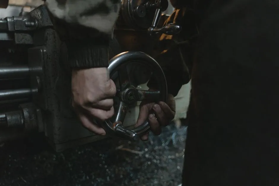
In a hot strip mill or cold reversing mill, the clutch and brake are not generic motion-control parts; they are the components that absorb the regenerative energy of decelerating coilers, hold screwdowns against strip tension, and index the runout table under cyclic shock loads. Sizing therefore starts from MAX TORQUE (T, Nm), SLIP SPEED (rpm), and KINETIC POWER (W), the three parameters Magtrol publishes as the hard inputs to any brake-clutch selection [S6].
Steel mills also stress these parts harder than most plants: ambient temperatures near reheat furnaces commonly sit 40-80°C, water and mill scale contaminate friction surfaces, and duty cycles are measured in stops per minute rather than stops per hour. Engineers should treat published dynamic torque ratings as the starting point, then derate for thermal capacity, environment, and the application's specific overload factor [S2][S4].
Clutch vs brake: function defines the mill station
Brakes are used to stop a load (typically a rotating load) while clutches are used to transfer torque, and that functional split maps directly onto mill stations [S2]. A coiler tension reel needs a brake, because the reel is decelerating a wound coil of strip, while a runout table or a shear drive needs a clutch, because the motor must keep running while the load engages and disengages on each cycle. Clutch-brake combination units fit stations where a load is started and stopped while the motor continues to rotate, a common pattern on coil-to-coil coilers and pinch roll stands [S2].
Twiflex-type caliper brakes and AC solenoid shoe brakes are the typical mill-duty brake architectures, used on cranes, gantries, and the unwind end of coil processing lines where the load must be held against strip tension [S2]. Drum brake families, with over 100 different models available from one major mill-duty supplier, are the workhorse holding brake on overhead cranes, ladle cars, and many material-handling auxiliaries inside the mill [S7].
Three governing spec numbers: torque, slip speed, kinetic power
To properly size a brake or clutch, the operating parameters of MAXIMUM TORQUE (T), SLIP SPEED (rpm), and KINETIC POWER (watts) will have to be determined, and these three values come straight from the mill's cycle [S6]. The maximum torque requirement on a coiler mandrel is set by strip tension × coil radius at maximum build, and it grows as the coil builds. Slip speed at the friction interface is the relative speed between rotor and stator during engagement, which can be several hundred rpm on a high-speed coiler but only tens of rpm on a slow screwdown.
Kinetic power (P = T × ω) is the heat dissipation budget for each engagement. For a mill reversing on a 90-second cycle that dissipates 200 kW peak during each plug, the brake must be able to absorb that without fading; Magtrol's guidance is to compute P first, then check that the candidate unit's continuous thermal rating exceeds the average dissipation over a full cycle [S6]. In aggressive cycle-rate applications, the manufacturer should be consulted on heat dissipation capacity, because stock selection charts only cover the steady-state envelope [S2].
Mounting, frame size, and coil voltage
Mounting is a hard constraint on a mill retrofit, not a free choice. Both clutches and clutch brakes can mount to the motor shaft or be base-mounted and have input via a belt drive, chain drive, or coupling, but the existing foundation, shaft alignment, and coupling spacing usually force one of the two [S2]. Motor frame size then determines the unit's shaft size, because most mill-duty clutches and shaft-mounted brakes share a frame family with the drive motor.
Coil voltage for electrically released units is 6, 24, or 90 Vdc, with 90 Vdc widely preferred in North American mills and 24 Vdc more common in Europe; AC-to-DC power supplies are normally supplied by the clutch or brake manufacturer to bridge the two standards [S2]. For a steel mill, this is more than a wiring preference: 24 Vdc control simplifies integration with modern PLC safety relays and allows the unit to be held released under SIL-rated monitored stop, while 90 Vdc is still the default where legacy 1950s-era mill control cabinets are in service.
Dynamic vs static torque, and the overload factor
Quick-selection charts from manufacturers list dynamic torque capacity and the matching motor torque at the unit's mounting speed, then apply an overload factor of some value to cover inrush and stall events [S2]. For a mill coiler, that overload factor is typically 1.5-2.0× the steady running torque, because the strip tension spike at the weld entry and the acceleration of a fresh coil both ask for short-duration torque well above the running average. Specifying a unit only on running torque is the most common cause of premature lining wear and rotor overheating on mill coiler brakes.
Static torque, by contrast, matters most for holding functions, the ladle turret lock, the screwdown hold against strip back-tension, the coil car park brake. For these stations, a spring-set, electrically released brake with a published static (or holding) torque rating of 1.25-1.5× the maximum hydraulic hold force gives the necessary safety margin. Coupler brakes such as the Posistop and MagnaShear families mount between motors and reducers, eliminating the need for a separate brake motor and saving the axial footprint on the gearbox input shaft [S2].
Material choices for the rotor, armature, and hub
For electromagnetic clutch parts, the contact surfaces are typically not surface-hardened, and the bulk material is most often a low-carbon silicon steel similar to motor and transformer lamination stock, which machines cleanly, retains no residual magnetism after the coil is de-energized, and resists rust on bare machined surfaces [S5]. Some heavy-duty mill clutches specify a higher-carbon variant, around 1% carbon content, to extend wear life on the driving teeth and hub splines, where hardness rather than magnetic behaviour governs service life.
For the friction interface itself, mill-duty brakes and clutches use high-energy organic linings, sintered bronze, or wet-running paper-based friction materials; the choice is governed by slip-speed and energy-per-stop rather than by aesthetics. A wet clutch running in pressurized hydraulic fluid is the standard answer on a coiler mandrel, where continuous slip would destroy a dry friction disc in minutes. For background on how the magnetic side of these components is engineered, the electromagnetic brake reference page covers the magnetic circuit and armature air-gap behaviour that govern release time and residual torque.
Mill-specific failure modes and constraints
The four failure modes a mill engineer watches for are: (1) thermal fade, where repeated high-energy stops overheat the friction stack and drop the dynamic torque coefficient; (2) oil contamination, which kills dry friction coefficient and welds wet-pack discs; (3) misalignment, which loads the bearing and the armature air gap unevenly; and (4) corrosion of unsealed friction surfaces during mill shutdowns, particularly in cold mills and finishing lines where condensate accumulates [S4]. Each of these is a derating factor on top of the published torque capacity.
Operating environment, temperature requirements, response time, power source, cost, and maintenance requirements are the secondary variables that almost always appear in a mill specification review, and each of them typically tightens the spec rather than loosening it [S4]. The clutch-brake reference page covers how the combined unit behaves under repeated start-stop cycles versus a standalone clutch or brake.
Selection criteria for the four common mill stations
Across the four most common mill stations, the decision criteria line up differently: (a) a coiler mandrel brake needs high dynamic torque at moderate slip speed and the largest possible thermal capacity, normally met by a wet hydraulic brake; (b) a runout table roll clutch needs fast engagement, moderate torque, and dry or oil-mist friction, normally met by an electric shoe clutch; (c) a screwdown holding brake is a low-speed, high-static-torque, 100%-duty holding service, met by a spring-set, hydraulically or electrically released unit; and (d) a shear or cropper clutch needs very fast response, accurate stop positioning, and a high cycle rate, met by a dedicated clutch-brake combination with braking torque to match the motor's plug-reversal capacity [S2][S3][S4].
For a useful side-by-side, the coupling-clutch reference page covers the integrated coupling-clutch units that combine torque transmission with controlled engagement, and is a useful comparison point when sizing mill drives that need both functions in one housing. For mill engineers cross-specifying friction materials and structural steels, the alloy steel and carbon steel reference pages cover the bulk-material options for hubs, rotors, and armature plates. For application context on how a comparable heavy-industry drive train is specced, the Clutch and brake selection for cement plant drives: a 2026 spec map article is a useful cross-check on dynamic torque and heat dissipation numbers in an adjacent high-inertia industry.
What a final steel mill spec sheet should list
A complete steel mill spec entry should carry, at minimum, dynamic torque (Nm), static or holding torque (Nm), maximum continuous slip speed (rpm), thermal capacity per engagement (kJ) and continuous (W), required coil voltage (Vdc), release time (ms), engagement time (ms), friction material grade, hub bore and keyway per the drive motor frame, mounting configuration (shaft-mounted vs base-mounted), and the environmental rating for mill atmosphere including temperature range and any required enclosure class [S2][S6]. Mounting interface, motor frame, and the mill's existing control voltage usually force the housing choice; torque, slip speed, and thermal capacity then narrow the unit within that housing.
Specifying a brake or clutch on any one of these numbers alone is the fastest way to shorten service life; the engineering work is in the combination, and a 5-10% torque oversize that doubles the thermal margin is a much better mill decision than a 50% torque oversize that runs the unit at the same peak temperature. The brake resistor reference page covers the related problem of dissipating regenerative energy on the electrical side of the drive, which is often specified in parallel with the mechanical brake on a modern mill stand.
For an engineer who has the dynamic torque, slip speed, and cycle data, the next step is the manufacturer's quick-selection chart for the chosen frame family, then a thermal verification against the average dissipation over a full mill cycle. If the cycle rate is aggressive for the load inertia, the manufacturer's application engineering team should be looped in before the order is placed, because the stock selection charts only cover the steady-state envelope [S2].