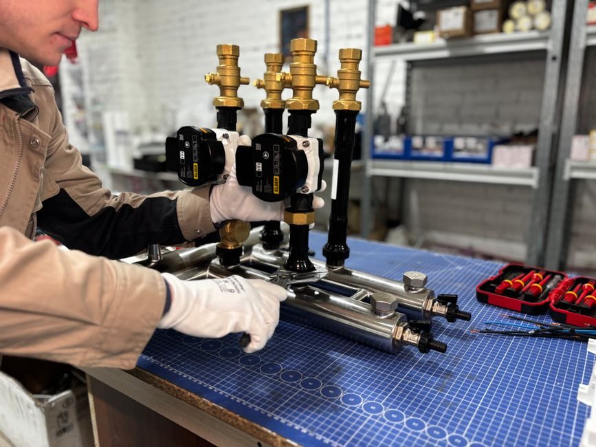
Five sequenced checkpoints — foundation and level, electrical supply with PE, compressed-air supply, strap-path calibration, and safety-circuit verification — cover the bulk of strapping-machine installation defects, per OEM integration guidance and industrial-vendor system docs [S1][S2][S3].
PP-strap automatic units like the ISG Pack Speed Strap 505 ship as 1,240 × 630 mm, 1 kW, 220 V single-phase machines running up to 65 p/min, so site prep is driven by the package envelope, not the line throughput [S2]. The TITAN VK10K120-16 strap head with SIEMENS PLC is a typical high-end pallet configuration [S1].
Foundation, Level, and Footprint Allocation
Floor flatness under the machine base should be held to ≤ 2 mm/m before anchor bolts are torqued, otherwise the strap-arch geometry drifts and tension uniformity falls outside spec [S1].
For semi-automatic units such as the S-313D (2,000 mm wide × 1,850 mm tall, 800 mm package width), operators need at least 600 mm of clearance on the strap-feed side for coil change-out and 1,000 mm at the arch opening for forklift access [S1]. A-93L-class compact automatic units (800 × 1,200 mm) suit small-carton cells, but their 3 p/s rating only holds when the surrounding conveyor remains within ±5 mm of the machine centreline [S1]. Plan the layout against the largest foreseeable pallet — not the day-one SKU — to avoid retrofits later; for broader equipment-layout context see this packaging line integration overview.
Power, PE Grounding, and Control-Voltage Wiring
Automatic units drawing 1 kW at 220 V single phase must land on a dedicated MCB with PE continuity verified at < 0.1 Ω, and the 24 VDC brushless drive bus on machines such as the Speed Strap 505 must be grounded at the same star point as the touch-screen HMI to avoid common-mode faults [S2].
Three-phase high-throughput pallet strap machines like the SKV-1220 (1,300 × 1,300 mm package, 2,000 mm height) require a Siemens PLC cabinet tied to the plant's protective-earth mesh, not a floating ground rod, because the TITAN VK10K120-16 sealing head dissipates heat through the chassis and a floating PE will lift the touch-screen reference [S1]. Conduit runs should keep at least 200 mm separation from VFD power cables; for related mechatronic install discipline on rotating equipment, the roller bearing installation guide is a useful cross-reference.
Compressed-Air Supply and Pneumatic Top-Press Setup
Versions equipped with a pneumatic top-press stabilizer must receive air at 6 bar (87 psi) regulated, dried to a −20 °C pressure-dew point, and filtered to 5 µm or finer — moisture is the leading cause of seal-jitter on heat-bond PP strap heads [S2].
The Easyfast® strap-guide on the Speed Strap 505 disassembles tool-free, so a 5 µm filter with auto-drain pays for itself in avoided seal-cooling faults [S2]. For installations where the line builder also runs a stretch wrapper downstream, set the regulator downstream of the first shut-off valve to prevent oil-back into the strapper's HMI pneumatic switch; for reference on how airflow quality maps to other pneumatic-fed machines, the shotcrete machine install steps cover a similar dry-air logic.
Strap-Path Calibration and Tension Set-Point
Strap width on PP-strap automatics covers 5–12 mm, external coil diameter 400–450 mm, and digital tension is settable up to 45 kg — these three parameters are interlocked, so changing the strap coil without re-teaching the HMI tension curve is a documented cause of 3–5 % reject rates at start-up [S2].
The empty-strap sensor and the optical sensor on the work surface must both see the strap loop before the foot-pedal cycle is enabled; if either flag is masked during commissioning, the head will execute a "dry cycle" and overheat the sealing blade [S2]. On pallet lines handling unstable loads, plan for both horizontal and vertical strap passes, with the vertical pass used to anchor the load to the pallet base [S3]. For a class-level comparison of semi-automatic vs. automatic vs. manual units, the strapping machine spec map lays out the envelopes side by side.
Safety-Circuit Verification and Acceptance Test
Every automatic strapper ships with magnetic safety sensors on the access doors, an emergency-stop button, and a strap-loop ejection routine for accidental cycle starts — all three must be functionally tested with the guard interlock forced open before the line is signed off [S2].
Acceptance criteria worth recording at commissioning: cycle rate within ±5 % of the rated p/min (65 p/min ceiling on Speed Strap 505), strap-tension set-point within ±2 kg of the programmed value, and a 30-minute continuous run with zero seal-cooling alarms [S2]. For high-throughput lines handling awkward or hot loads, escalation paths include upgrading to a four-swivel caster mobile arch and fitting adjustable sealing-cooling time (COOL TIME) so operators can tune for ambient shifts [S2]. If commissioning fails twice on the same failure mode, replace the strap head rather than re-calibrate — the TITAN VK10K120-16 has a finite seal-blife that is not recoverable by re-teach [S1].
Track the next strap-head service interval at roughly 2,000 operating hours for PP-strap automatic machines, and verify at every PM that the four swivel casters (two braked) are still locking — a drifted caster is the root cause of most "phantom" mis-feed faults logged on otherwise healthy units [S2].
The underlying component specifications are covered under strapping machine, linear guide, and strapping band.