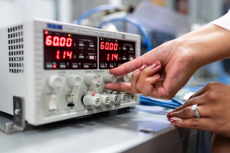
Switching power supplies are now the default for industrial control cabinets, delivering 24 VDC at efficiencies above 85% in compact DIN-rail housings while weighing 40–60% less than equivalent linear units [S1][S2].
Correct sizing hinges on four numbers: nominal load in amps, peak inrush, ambient temperature, and the longest wire run. The walk-through below uses a 24 VDC control panel as the worked example, because 24 VDC remains the most specified control voltage for PLCs, sensors, relays, HMIs, and solenoid valves [S3][S5].
Define the Output Voltage and Load Budget Before Watts
The first selection gate is output voltage, not wattage: a 12 VDC, 24 VDC, or 48 VDC PSU must match the equipment label exactly, and 24 VAC will not substitute for 24 VDC unless the device is dual-rated [S2]. Standard industrial rails sit at 5 VDC, 12 VDC, 24 VDC, and 48 VDC, with 24 VDC dominating PLC and sensor panels [S2].
For a 24 VDC rail, total nominal load is the sum of every device powered from the same branch: PLC CPU, digital inputs, analog modules, Ethernet switch, HMI, relay coils, and indicator lights. At 24 VDC, 12 W equals 0.50 A, 60 W equals 2.50 A, 120 W equals 5.00 A, and 240 W equals 10.00 A; convert wattage to amps before adding, or the safety margin gets applied twice [S3]. A switching power supply that is undersized for ampere budget will sag under steady load even if its watt label looks generous.
Apply the 20–30% Continuous Margin, Then Add Inrush Headroom
Multiply the calculated nominal load by 1.20 as a baseline for long service life, and by 1.25–1.30 when the cabinet runs warm or expansion is planned [S3][S2]. For example, a 24 VDC / 5 A steady load (120 W) becomes a 150 W supply at 25% margin, stepping up to 24 VDC 180 W or 200 W if ambient is high or the load fluctuates [S2].
Inrush is a separate test. Switching supplies draw 3–5x rated input current during capacitor charge at turn-on, and downstream loads such as solenoid valves, contactor coils, and motor starters stack their own inrush on top [S4]. A 24 VDC 10 A supply that passes a steady-state bench test can still collapse to 18 V at the device terminals when eight relays pull in together, so check the PSU's peak/short-term current rating against the sum of coil inrushes for 100–500 ms [S3]. A DC power supply datasheet that omits dynamic load behaviour is a red flag for any panel driving more than three inductive loads.
Derate for Temperature and Verify Voltage Drop at the Farthest Terminal
Industrial DIN-rail power supplies typically require temperature derating and margin, with a common sizing practice of multiplying the calculated nominal load by 1.20 for long life [S3]. A 240 W (10 A) unit in a sealed cabinet at 60°C may only deliver 8 A continuously; a power supply spec sheet that quotes watts at 25°C is not the number to design against.
Voltage drop is the silent killer. For 24 VDC control circuits, target under 3% drop (about 0.72 V) at the farthest device, which for a 5 A load on 18 m round-trip cable typically requires 2.5 mm² (14 AWG) or larger conductors [S3]. Measure voltage at the device input pin, not the PSU output terminal, because the same circuit that passes a bench check can sag 1.5 V under load at the end of a long run.
Branch Protection, Inrush Limiters, and Breaker Coordination
Each 24 VDC branch needs its own fuse or DC-rated circuit breaker sized at 1.25–1.5x the branch load, with the breaker's interrupting rating matched to the PSU's maximum short-circuit current [S4]. Use DC-rated breakers: AC breakers will not reliably interrupt a 24 VDC arc.
For supplies feeding large capacitive loads or long cable runs, add an inrush current limiter (NTC thermistor) at the PSU input to clamp turn-on surge to 1.5–2x rated, which prevents nuisance tripping of the upstream 230 VAC breaker and extends electrolytic capacitor life [S4]. A 24 VDC 5 A PSU on a 230 VAC single-phase input typically pairs with a C-curve 6 A or B-curve 10 A MCB, depending on PSU inrush characteristics [S4].
Redundancy, DC UPS, and When a Linear Supply Still Wins
Critical PLCs and safety circuits warrant 1+1 parallel redundancy with two supplies on a diode-OR or active current-share module, sized so either unit alone carries the full load. A small industrial UPS or supercapacitor module on the 24 VDC rail bridges PLC ride-through for 200 ms to several seconds, holding processes through brownouts and brief outages without a full restart cycle [S3].
Linear supplies still have a niche where their lower EMI floor matters: precision analog front-ends, low-noise sensor excitation, and laboratory instrumentation with sub-mV ripple budgets. For any application above 50 W or with a thermal budget below 1 W per cm², the switching topology wins on efficiency, weight, and cost [S1].
Comparison Matrix: 60 W / 120 W / 240 W / 480 W at 24 VDC
The decision below maps common DIN-rail ratings to typical control-panel loads. All four assume a 24 VDC output, full load at 50°C with 1%/°C derating above, and a 25% continuous margin already applied [S3][S5].
For a small sensor panel (8–16 discrete I/O, one Ethernet switch, no HMI), a 60 W (2.5 A) supply covers about 2.0 A of steady load, leaving room for two or three future sensor additions. For a mid-size PLC panel with CPU, 32 digital I/O, analog module, and 7-inch HMI, a 120 W (5.0 A) unit handles roughly 3.8 A continuous and absorbs relay-coil inrush within its 150% short-term rating. A 240 W (10 A) supply is the workhorse for multi-PLC cells, multiple HMIs, and small VFD auxiliaries, typically delivering 8 A continuous at 60°C cabinet temperature. At 480 W (20 A) and above, parallel redundancy, DC bus distribution, and a dedicated industrial UPS module become standard, with wire sizing and branch protection dominating the bill of materials.
Common Sizing Mistakes and How to Avoid Them
Three errors cause most field failures. First, sizing to nameplate watts without converting to amps and applying margin leads to thermal trips within months [S3]. Second, ignoring ambient derating inside a sealed cabinet: a 10 A supply at 25°C is an 8 A supply at 60°C [S3]. Third, forgetting DC OK signaling and remote sensing; long cable runs and redundant supplies need these to function correctly [S3][S5].
A related selection guide worth cross-reading: PLC Power Supply Sizing: How to Estimate I/O, Module, and Load Current walks the same worksheet method from the load-side view, useful when the panel I/O list is the input rather than the supply catalog. Skip oversized units with no UL/IEC 61010-3-1 or IEC 61204-7 CE mark, since unlisted supplies are a frequent cause of inspector rejections on North American and EU builds [S2].
Final shortlist logic: confirm 24 VDC output, pick the next standard watt size above 1.25x the ampere budget, verify derating at the cabinet's worst-case ambient, and confirm branch protection plus DC OK signaling before releasing the BOM. Trackable signals to watch are revisions to IEC 61204-7 for DC-output low-voltage supplies and updates to UL 508A panel-builder short-circuit current tables; both directly affect how a 24 VDC supply gets protected and labeled inside an industrial cabinet [S2][S4].