ZLP-series suspended working platforms, where the model number equals the rated load in kilograms (ZLP250, ZLP500, ZLP630, ZLP800, ZLP1000), remain the default electric cradle for façade, curtain wall, and structural steel envelope work at height [S1].
Selection for a steel-construction site is driven by four hard numbers: the platform's rated load, the working height, the wire rope diameter and breaking force, and the safety-lock configuration. Window cleaning and light repair use ZLP500/630; curtain wall installation and heavy steel envelope work starts at ZLP800; high-volume material lifts step up to ZLP1000 [S1].
Match Load Class to Steel Work, Not to Basket Size
Rated load is defined as workers' weight plus tools plus materials, with a safety margin; this calculation is step zero before any model discussion [S1]. The industrial convention is that the model number itself is the rated load in kilograms, so a ZLP630 platform carries 630 kg of total payload, while a ZLP800 carries 800 kg [S1]. For steel construction this matters: two ironworkers at roughly 100 kg each, plus welding sets, plus section steel, push a 250 kg basket past its limit in a single lift.
Curtain wall installation and heavy steel envelope work are explicitly mapped to ZLP800 and above in current buying guides, with ZLP630 reserved for lighter façade cleaning and minor repair [S1]. A criteria-based comparison of the four common ZLP classes against steel-site payloads and the rope sizes they pair with: ZLP630 pairs with 6 mm wire rope (breaking force ~30-35 kN) for jobs under 100 m; ZLP800 pairs with 8 mm rope (breaking force ~50-60 kN) for lifts above 150 m or heavier payload brackets; the ZLP1000 class steps up to 10 mm rope (breaking force ~70-85 kN) for capacities exceeding 800 kg or extreme heights [S4].
Five Non-Negotiable Safety Items, No Shortcuts
A qualified suspended platform must carry five baseline items: a service brake built into the hoist, two fall arrest devices (safety locks) acting on independent safety ropes, two upper limit switches to prevent overtravel, an emergency stop, and a controlled-descent function that lets the brake be manually released on power loss instead of leaving workers hanging mid-air [S1]. Missing any one of those five is described as unacceptable in current selection guidance [S1].
The safety lock is treated as a separate purchase decision rather than a line item: prefer anti-tilt designs (LSF series is named as a reference), require a minimum of two units, and insist on CE / TÜV / SGS certification [S1]. For steel sites where temporary power trips are common, the controlled-descent function earns the most weight because it converts a stranded-at-height incident into a recoverable condition [S1].
Hoist Specs: IP55, α Wire Guiding, and Dual Hoists
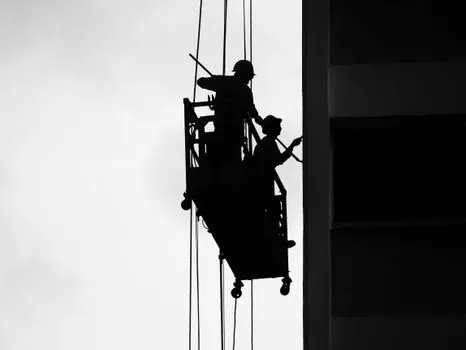
Suspended platforms are typically driven by two electric hoists, one at each end of the platform, and the hoist is treated as the power core rather than a commodity [S1]. Mature hoist designs use an "α" wire guiding system, which reduces wire-rope wear and extends service life on repeated bending cycles; cheaper drum geometries are a known source of premature rope failure [S1].
Outdoor operation in wind and rain drives the protection rating to a minimum of IP55 [S1]. The same controlled-descent requirement that applies to the safety system applies to the hoist brake: the electro-mechanical brake must be manually releasable, with an integrated centrifugal force brake providing slow controlled descent rather than a free fall on power loss [S1]. This is consistent with broader construction machinery and equipment practice for man-riding lifts, where braking redundancy is treated as a single failure-mode problem.
Wire Rope Sizing: 6x19S+IWR, 10x Safety Factor
The 6x19S+IWR (Independent Wire Rope Core) construction, 6 outer strands of 19 wires each around an IWRC central core, is the industry standard for suspended platform ropes, balancing flexibility with fatigue life over repeated winch-drum bending [S4]. Alternative constructions are used at the edges: 6x36S+IWR for higher flexibility on larger drum diameters, and 18x7 non-rotating ropes where torque on a single line is a concern [S4].
Wire rope selection must confirm a minimum 10x safety factor against maximum working load per EN1808 and OSHA requirements, so the rated breaking force of the rope must be at least ten times the maximum load it will ever see in service [S4]. Diameter selection per current manufacturer guidance: 6 mm rope suits standard platforms up to 400 kg at heights under 100 m, with breaking force around 30-35 kN; 8 mm rope handles 400-800 kg capacities or heights above 150 m, with breaking force around 50-60 kN; 10 mm rope is reserved for heavy-duty use above 800 kg or extreme heights, with breaking force around 70-85 kN [S4].
Material selection is a corrosion decision, not a strength decision. Galvanized carbon steel suits standard inland environments with a 2-3 year service life under normal conditions; stainless steel Type 304 covers general coastal and mildly corrosive sites with a 3-5 year life; stainless steel Type 316 is required for high-salt environments such as tropical coastal zones, swimming pool facilities, or industrial areas with acidic atmospheres, with a 5-8 year life at roughly 2.5-3x the cost premium over galvanized rope [S4].
Rope Retirement: Six Broken Wires, 10% Diameter Loss, Any Pitting
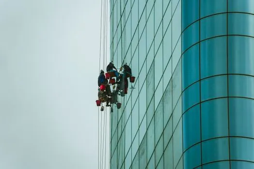
Retirement criteria are defined under EN1808 and OSHA 1926.502, and a single criterion being met mandates immediate retirement of the rope [S4]. The four governing checks: more than 6 broken wires within one rope lay length (lay length equals 6-8x rope diameter); 3 or more visible broken wires at either rope termination; pitting corrosion or any stiffness/crunching on a soft-bend test indicating internal corrosion; and diameter reduction exceeding 10% of nominal diameter, which means a 6 mm rope must be retired at 5.4 mm and an 8 mm rope at 7.2 mm [S4].
Deformation defects are also mandatory retirement triggers, regardless of remaining diameter or broken-wire count: kinking from improper handling, birdcaging from shock loading, crushing from impact or drum contact, and core protrusion where the IWRC shows through the outer strands [S4]. Light surface oxidation can be addressed by cleaning and re-lubrication, but only with continued monitoring rather than a clean retirement signal [S4].
Lubrication Schedule: Monthly, Correct Grease, 30-50% Life Gain
Proper lubrication extends rope service life by 30-50% and is a documented maintenance line, not optional cleaning [S4]. The lubricant must be specifically formulated for wire rope; motor oil and general-purpose grease are not acceptable substitutes [S4]. Standard practice is monthly lubrication on suspended platform ropes, with increased frequency in harsh environments, and a structured lubrication record kept per rope so that retirement-age decisions have a maintenance history behind them [S4].
The site reality is that suspended platform ropes, hoist service brakes, and the upper limit switches are the three subsystems that fail first on steel-construction sites with long campaigns, and they are also the three that map directly to the suspended platform retirement schedule under EN1808. Operators running 8 mm Type 316 rope at a coastal port have a different inspection cadence from operators running 6 mm galvanized rope on an inland tower, and the standard lets each rope's recorded maintenance drive the retirement call [S4].
BMU, Wind, and Marine Alternatives Outside Construction Steel
Electric suspended platforms cover construction, façade access, wind power maintenance, and marine/offshore use; the same ZLP base platform is reconfigured with different rigging, hoists, and safety devices for each duty cycle [S3]. For permanent façade access on tall buildings, a Building Maintenance Unit (BMU) is the engineered alternative to a temporary ZLP, with a roof-mounted cradle and dedicated track rather than a roof-suspended wire-rope rig [S3].
Wind power and marine variants inherit the same hoist and safety-lock architecture but use higher-grade wire rope, corrosion-resistant rigging, and marine-rated electrical control cabinets [S3]. For a steel-construction site that is not at the coast and not on a wind turbine, a standard ZLP800 with 8 mm galvanized 6x19S+IWR rope, dual IP55 hoists, two anti-tilt safety locks, and monthly lubrication is the practical baseline; jumping to Type 316 rope only pays back when the project is genuinely within a corrosive atmosphere envelope. For a broader view of how this category fits against other access options, the suspended platform reference page lays out the design envelope, and adjacent access gear such as construction tools and suspended ceiling systems sit on the same lifting-and-rigging decision tree.
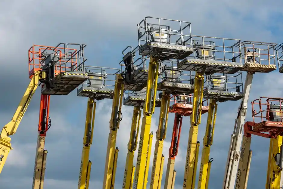
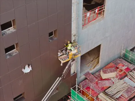
For steel-construction work that is better served by boom-based reach than rope-suspended cradles, articulating and telescopic platforms on the construction machinery and equipment side of the catalog cover projects where lateral reach, subsoil limits, or emission rules rule out a roof-suspended ZLP [S2]. Where payload is a hydraulic tool plus crew, the basket rating must absorb the tool's reaction forces and changing center of gravity, not just the workers' body weight [S2].
Trackable signals worth watching: any tightening of the 10x safety factor in EN1808, a migration from galvanized to Type 316 rope as default on multi-year coastal projects, and BMU market drift on tall-steel envelope work where permanent track begins to displace temporary ZLP rigs. For a comparative lift in the same steel-construction envelope, the climbing formwork selection for bridge pylons and piers piece maps the matching pylon-side access problem, and the slewing drive selection for material handling article covers the rotation-rated machinery that often sits at the base of the same steel envelope.