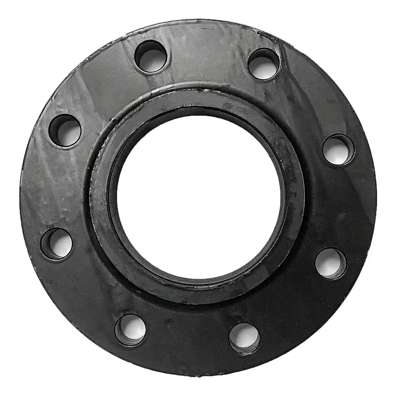
A blind flange is a forged steel disk drilled with a bolt hole circle and no center bore, bolted onto the mating flange at a pipe end, a vessel nozzle, a valve, or a flanged pipe fitting to close the line at the full pressure rating of its class. Because there is no bore, the part works as a flat pressure head rather than a flow component, and it is the thickest member of the flange family at any given size and class: a Class 150 NPS 4 blind runs about 32 mm thick and a Class 600 NPS 4 about 57 mm, against noticeably slimmer bored flanges of the same class. Plant vocabulary says blank flange just as often; this page uses the standard name and treats the other as a synonym. What the product buys is a closure that is positive by geometry, not by seat condition: metal against gasket against metal, with no stem, no packing, and no leak path that wear can open.
Procurement engineers specify these closures at hydrotest boundaries during construction, at future expansion nozzles on vessels and manifolds, at instrument tappings taken out of service, and at idle ports on changeover hardware such as a duplex strainer running on one basket. The decision this page settles is narrow and practical: which dimension standard and class govern the disk, which facing and surface finish the mating parts need, which forging matches the temperature and the chemistry, and which gasket and stud bolt package makes the joint hold at test pressure and at operating temperature. The answer lands as an RFQ line set sized under ASME B16.5 or ASME B16.47 and assembled under ASME PCC-1 practice, and every chapter below feeds that line set so the closure is bought, not improvised from whatever the stores had on the shelf.
This page treats the blind flange as a purchasing object: how the flat plate thickness and the bolt load interact, what each facing demands from gasket and finish, which forgings cover which temperature and chemistry, how a blind behaves as a hydrotest closure, and how all of it combines into a defensible RFQ line set. It is written for engineers who issue purchase specifications, not for readers who want a brochure summary.
Chapter 1 / 06
What a Blind Flange Is and What Is Being Decided
The absence of a bore is the entire definition. Every other flange in the dimension standards exists to put fitting or pipe wall around a hole: weld neck for the pressure spine, slip on for economy, lap joint for the rotating companion, threaded for the pipe crew. The blind flange exists to end the hole. It carries the same facing, the same bolt circle, and the same class as the mating flange, so the line rating flows straight through the closure, and it is a pressure part rather than a pipe fitting: it carries no flow, it matches no pipe schedule, and it is chosen from the dimension tables of the flange standard rather than from the bore logic of a piping specification. That distinction matters at order time, because a buyer who treats the closure as a fitting gets a disk chosen by habit instead of by class, and the joint either leaks at test or wastes forging weight for decades.
What is actually being decided in this purchase is a set of five commitments made in one line set. First, a size and class commitment: NPS and pressure class from the line standard, checked against the pressure temperature tables at operating temperature, not just at ambient. Second, a facing commitment: raised face, flat face, or ring type joint, decided by the mating flange and its material rather than by preference. Third, a forging commitment: ASTM A105 as the carbon steel default, low temperature and alloy and stainless grades where the service demands them. Fourth, a gasket commitment, because the facing and the gasket are one decision split across two purchase lines. Fifth, a bolting and assembly commitment: stud length, nut, lubrication, and the torque sequence that seats the joint. A quotation that answers only the size has quoted a disk of steel, not a closure.
Against its neighbors, the blind flange occupies deliberate ground, and the full comparison belongs in the selection chapter. A gate valve or a ball valve isolates for operations, but both shut by seat contact and seats wear; a butterfly valve does the same rotational duty at large bore and lower cost with the same seat honesty. A check valve answers only the reverse flow question. None of the three is a positive geometry closure, none holds a hydrotest the way a bolted flat head does, and none of them is the right answer when the line ends on purpose. Where the pipe must simply stop, and stay stopped without a stem or a seat in evidence, the bolted disk is the industry default across water, steam, hydrocarbon, and chemical service alike.
Four standards organize the datasheet, with three more in support. ASME B16.5 governs flanges from NPS 1/2 to NPS 24 at Class 150 through Class 2500: diameter, thickness, bolt circle, drilling, facing dimensions, and the pressure temperature ratings by material group. ASME B16.47 takes over from NPS 26 to NPS 60 in Series A, the MSS SP-44 lineage with heavier bodies, and Series B, the API 605 lineage with lighter drilling. ASME B16.21 dimensions the gaskets that sit in the joint, and ASME B16.34 supplies the valve and flange component pressure temperature logic that the derate discussion leans on. ASME PCC-1 governs how the bolted joint is assembled, and ASME B46.1 defines the surface finish language the facing paragraph needs. A datasheet that quotes none of these is a price tag, not a specification.
The RFQ should also state the station, because the closure never arrives alone. The gasket is chosen with the facing and the stud bolts with the class, and the surface finish is chosen with the gasket: a spiral wound gasket wants the serrated raised face it can bite into, a soft cut gasket wants the same finish at lower load, and a ring joint wants its groove machined to the standard and protected until the ring lands in it. On a shutdown spool the blind may share its work order with the steam trap stations being serviced beside it, and on a commissioning header it closes the test point that the flushing crew used all month. Stating the station in the RFQ lets one supplier check facing, drilling, gasket, and stud compatibility in a single pass instead of four arguments at delivery.
Chapter 2 / 06
How the Blind Flange Holds Pressure
Mechanically the blind is a flat circular plate clamped at its bolt circle and loaded by pressure across its full face, and that is the least forgiving geometry in the flange family. In words rather than symbols: the bending demand on the plate grows with the square of the diameter and falls with the square of the thickness, so doubling the bore at the same class calls for roughly four times the bending capacity, and thickness is the only lever the geometry has. That single relationship explains the dimension table at a glance: the thickness column moves more between classes than any other column, which is why the Class 150 NPS 4 disk at about 32 mm becomes about 57 mm at Class 600, and why large bore blinds from the B16.47 tables are massive forgings whose weight and lifting plan belong in the installation discussion, not an afterthought.
The bolt load path is the second half of the mechanics. The stud circle has to react two loads at once: the end load from pressure acting on the full bore area, and the residual compression that keeps the gasket sealed against blowout and leakage. The gasket needs a minimum seating stress to conform to the flange finish, and then a lower but continuous operating stress to stay sealed as pressure and temperature cycle. Because the blind has no pipe hub to share the moment, the studs carry the whole story, which is why assembly practice under ASME PCC-1 matters on this joint more than on any bored flange: cross pattern passes, incremental torque steps, a target bolt stress rather than a bare torque number, and stud length chosen so every nut engages fully with two to three threads showing past the nut face.
The facing decides how that clamping load becomes a seal. The raised face concentrates the bolt load on a ring roughly from the bolt hole inner edge to the bore, finished with a serrated or concentric pattern in the 125 to 250 micron AARH range defined by ASME B46.1, and that roughness is functional: it gives a soft or graphite filled gasket something to conform into and gives a spiral wound gasket the friction that stops it unwinding. The flat face spreads the load over the whole mating surface, which is exactly what a brittle partner needs: cast iron, glass lined steel, and plastic bodied equipment are bent, not sealed, by a raised face, and the flat face with a full face gasket removes the bending moment. The ring type joint abandons the flat sealing surface entirely: the facing carries a machined groove, an octagonal or oval section metal ring from the numbered table in the standard seats in it, and the seal is metal to metal at contact stress that holds at temperatures where soft gaskets long since gave up, which is why RTJ territory starts around Class 900 and owns everything above it.
Temperature derate is where careless purchases fail. The class number is a cold rating in the sense that the pressure temperature tables in B16.5 rate each material group at each temperature, and the allowable pressure falls as the metal weakens. As a family pattern, a Class 150 carbon steel blind carries about 19 bar cold and about 12 bar at 260 deg C, and a Class 600 carries about 100 bar cold with a proportional slide; the tables by material group govern the exact figure. The trap is the hydrotest plan: system tests run at ambient temperature, commonly at about 1.5 times design pressure, exactly where the rating is at its highest, so a closure that survives the test comfortably can still be underclassed at operating temperature. The class decision is made against the derated table at operating conditions, then checked at test, never the other way around.
At large bore the physics adds tolerance problems on top of thickness. A NPS 36 or NPS 48 blind from the B16.47 tables is a disk of plate scale, and flatness and waviness tolerances become as important as the thickness itself: a disk that waves does not seat a gasket evenly no matter how well the studs are tightened, and an RTJ groove cut into a wavy face never seals. The standards carry the tolerance language, the receipt inspection should carry a straightedge and, for ring joints, a groove template, and the storage plan should keep large disks flat and dry until they go up. Large blinds are lifting and flatness problems before they are pressure problems, and the purchase specification should say so.
Chapter 3 / 06
Types, Facings, and Duty Boundaries
The family sorts by facing first because the facing is what the mating flange dictates. Raised face is the default for steel to steel joints at Class 150 through Class 600 and most utility and process duty beyond. Flat face follows the partner: cast iron valves and fittings, glass lined vessels, fiberglass and plastic headers all get a flat faced blind with a full face gasket, because seating a raised face against them cracks or bends the brittle member. Ring type joint facings, with the groove and the numbered metal ring, take over at Class 900 and above and dominate high temperature steam and hydrocarbon gas duty. One caution closes the sorting: a reducing blind, drilled and bored to pass a smaller pipe through it, has stopped being a blind flange the moment it acquired a bore, and it must be specified and rated as the bored flange it now is, never ordered on blind flange logic.
Materials sort by temperature and chemistry. ASTM A105 carbon steel is the default for ambient through moderate temperature service, with the normalized condition specified on heavier sections. Below minus 29 deg C the low temperature forgings take over: A350 LF2 is the workhorse, and the minus 46 deg C territory on the ASME B16.34 material curve belongs to impact tested LF2 and LF3 forgings. For hot service and hydrogen bearing hydrocarbons, the chrome alloy forgings F11 and F22 carry the duty as they do everywhere else in the line class. F304 and F316L stainless cover corrosion and cleanliness duty, and duplex 2205 answers hot chloride chemistry. Wet sour service adds NACE MR0175 and ISO 15156 material limits, hardness requirements included, and the certificates that prove them.
The duty list is where procurement volume actually lives. Construction and precommissioning use blinds as hydrotest closure points, bolted onto test headers and spool ends with a sacrificial gasket and removed or left in place per the tie-in plan. Vessels and manifolds carry future expansion nozzles blanked from the day they are built, waiting years for the connection they were drilled for. Instrument stations retire: an impulse line is isolated, the tube fitting unions and the instrument manifold or the diaphragm seal come off for reuse elsewhere, and a small blind closes the root connection so the tapping survives to the next project, where a needle valve may go back on it or nothing will. Changeover hardware blanks its idle ports: a duplex strainer running on one basket has its standby leg closed by class rated blinds that the maker drilled the body for, and pig receiver and launcher barrels are blanked between campaigns with their own closure hardware. Every one of those duties buys the same disk, but each pairs it with a different gasket and bolting story, and the selection chapter sorts them.
Boundaries deserve plain statements, because this component is regularly asked to do jobs that belong to neighbors. It is not a valve: a gate valve or a ball valve gives operations a controllable shutoff that wears and proves; a globe valve throttles, which a flat disk cannot begin to do. A check valve permits forward flow and blocks reverse, which is a flow logic no closure has. A rupture disk is a relief device that exists to fail at a set pressure, the exact opposite of a pressure boundary that must hold. A safety relief valve protects the system from overpressure and never closes a line in any sense. An expansion joint absorbs pipe movement that a bolted joint must never be asked to take. And for switcheable positive break isolation between maintenance domains, the line blinding family is a different product with a different specification world, a boundary the selection chapter draws properly. The blind flange is the permanent, pressure rated, geometry tight end of the line, and nothing else should be asked of it.
The duty map below consolidates the pairings into one table a specifier can scan before writing the RFQ.
Duty
Blind configuration to specify
Check before order
Hydrotest boundary, construction
A105N raised face, class matching 1.5 times design at ambient, sacrificial soft cut gasket
Test pressure against cold rating; stud length for test nuts
Future expansion nozzle
Class, facing, and forging matching the planned tie-in flange
Bolt hole orientation against future piping; gasket stored with the disk
Retired instrument tapping
Small size raised face or threaded per the root connection
Remove manifold or seal hardware first; tag the line out properly
Standby port on changeover body
Per the duplex strainer maker drilling, same class as the body
Interlock sequence before any blank is broken
Steam header temporary closure
F11 or F22 per line spec, RTJ above Class 600 with numbered ring
Derate at operating temperature, not just at test
Low temperature closure
A350 LF2 or LF3 with impact test certificates
Minus 29 and minus 46 deg C boundaries against the material curve
Large bore closure, NPS 26 to 60
B16.47 Series A or B per the line class standard
Flatness and waving tolerance at receipt; lifting plan
Chapter 4 / 06
Key Specification Parameters
The table below decodes the datasheet lines that decide whether a quoted disk matches the closure duty. Each row is purchase defining; the paragraphs after the table explain what to demand and what a weak answer looks like.
Attribute
Typical range or options
What it decides
Nominal size
NPS 1/2 to NPS 24 per B16.5; NPS 26 to NPS 60 per B16.47
Bolt circle, thickness, drilling, and which dimension table governs
Pressure class
Class 150 to Class 2500 in B16.5 steps; 150 to 900 in B16.47
Rating at temperature, thickness, and the stud package
Thickness, representative
About 32 mm at NPS 4 Class 150; about 57 mm at NPS 4 Class 600
Weight, price, and flat head capacity; the standard table governs
Facing
RF raised face, FF flat face, RTJ ring groove
Gasket type, finish, and which mating flanges are compatible
Surface finish, RF
Serrated or concentric, 125 to 250 micron AARH
Seating of soft and spiral wound gaskets; no finish, no seal
Temperature window, chemistry resistance, sour acceptance
Gasket
Soft cut at Class 150; spiral wound with inner ring Class 300 up; RTJ ring Class 900 up
Seal integrity at class and temperature
Bolting
Stud bolts per class table, full engagement plus 2 to 3 threads
Whether the joint can be tensioned to the target stress at all
Coating
Black oxide, anti-rust oil, FBE
Storage and atmospheric corrosion before and between services
Certificates
EN 10204 3.1 material certificate
Traceability of chemistry and heat treatment to the disk
The thickness row deserves its own paragraph because it drives weight, price, and lifting. Demand the dimension table reference by name, B16.5 or B16.47 Series A or B, and check the quoted thickness against it rather than against a remembered value: the about 32 and about 57 mm figures above are family markers, not substitutes for the table. Thickness is also the row where unofficial products show themselves, because a disk cut from plate to an approximate thickness carries no class at all, and a buyer who accepts it has bought unidentified steel with bolt holes. A class rated blind is a forging or a certified plate product with a certificate behind it, and the quotation should prove both.
The facing and gasket rows are one decision, and the table below pairs them the way the joint actually assembles.
Facing
Gasket practice
Where it is right
Raised face, serrated
Soft cut gasket at Class 150 utility; spiral wound gasket with inner ring from Class 300 up
Steel to steel joints across process and utility service
Flat face
Full face soft gasket, full contact
Cast iron, glass lined, plastic, and other brittle partners
Ring type joint
Octagonal or oval metal ring, number from the standard table
Class 900 and above, high temperature steam and gas
RTJ groove condition
Template checked, corrosion free, protected in storage
Wet sour and offshore service where pitting kills seats
Beyond the tables, the datasheet must state the evidence. Bolt hole count, diameter, and tolerance against the drilling table, so eight studs on an NPS 4 Class 150 arrive as eight and not as someone else's drilling, and so the disk drops onto a line flange or a flanged pipe fitting without reaming in the field. Facing diameter and raised face height, or groove dimensions and ring number for RTJ. The AARH finish value or its equivalent, because a smooth machine finish seats a spiral wound gasket badly and a coarse one wastes a soft one. The material grade with the normalized condition where the section calls for it, the impact test evidence on low temperature forgings, and the EN 10204 3.1 certificate that ties all of it to a heat number. Flange components are not individually hydrostatically tested as a rule, and a supplier who offers a hydro certificate on the disk itself is selling a system test or a story; the rating proof is the standard plus the material certificate.
Chapter 5 / 06
Selection Decision Factors and RFQ Language
The decision sequence is short enough to run as a checklist in a specification meeting, and each step eliminates a class of quotations before price comparison starts.
Confirm the duty honestly: permanent pipe end, future tie-in, test boundary, retired tapping, or idle port, because the duty sets the gasket and the retrieval plan, not just the disk.
Fix NPS and class against the line standard, then check the pressure temperature table at operating temperature and at test pressure before believing the class.
Choose the facing from the mating flange: never raise a face against a flat partner, never mix RF with FF, and reserve RTJ for the classes and temperatures that earn it.
Choose the forging from temperature and chemistry: A105 default, LF2 and LF3 below minus 29 deg C, F11 and F22 for hot and hydrogen service, stainless and duplex for corrosion, all under NACE MR0175 where sour applies.
Choose the gasket with the facing: soft cut at Class 150 utility, spiral wound gasket with inner ring from Class 300, RTJ ring at Class 900 and above.
Specify the studs as a package: diameter and length per the class table, full nut engagement plus two to three threads, anti-seize or lubricant named, and the PCC-1 target stress or torque table attached.
Fix the verification: dimension check against the named table, facing finish, flatness on large bore, and the EN 10204 3.1 certificate with the delivery.
State the station: order the gasket and studs with the disk, state the coating, and note whether the closure is permanent or will be broken at the next shutdown.
The isolation boundary deserves its own paragraph, because two different questions are routinely confused. For switcheable positive break isolation between two maintenance domains, the correct product is a spectacle blind or its spade and spacer relatives, hardware that swings or swaps a solid barrier into the line and shows its state to anyone walking past; that line blinding family has its own specification logic and its own page elsewhere in this encyclopedia when the batch that covers it ships. The blind flange is the permanent pressure boundary and the test closure, and on many headers the two are neighbors rather than substitutes: a gate valve or a ball valve for operations, a spectacle blind for the break, and a blind flange where the pipe genuinely ends. Within that division the valve questions answer themselves honestly: a globe valve throttles, a check valve blocks reverse flow, a butterfly valve economizes at large bore, and none of them holds a test or ends a line. A rupture disk stays on the relief side of the system where it belongs, and a safety relief valve assumes the line continues past it, which is the opposite of closure.
The consumables line thinks the same way as the hardware line. One gasket per stored closure, one spare element for the Y strainer, one basket for the basket strainer on intake duty, and one blank already drilled for the idle duplex strainer leg, all ordered against the same shutdown date, because station spares are specified in advance, not discovered at two in the morning. Buyers who treat the closure as a one line item and the station as someone else's problem re-engineer both under a shutdown clock, every time.
Retired instrument stations are the quiet volume user of small blinds, and they carry their own sequence. The loop is isolated at the root, the instrument manifold or the diaphragm seal comes off and goes back to the store, and the blind closes the connection so the process side survives to the next project without a hanging impulse line full of product. Where the station may return, the root valve stays and the blank goes on its outlet, and where the impulse tubing went with the instrument, the tube fitting unions come off with it so nothing corrosion prone is left hanging. That is also why the RFQ for instrument duty asks about connection type first and class second. On commissioning systems, the same small disks close the test points that the flushing crew used, and the work order should require the gasket to be new at every reassembly, because a test gasket reused into service is the cheapest leak on the plant.
The application map below turns the rules into a table the project file can carry.
Application
Construction to specify
Check before order
Utility air and water pipe end
A105 Class 150 raised face with soft cut gasket
Gasket inside the bolt circle, not overhanging the bore
Steam header end, Class 600
F11 or F22 raised face with spiral wound gasket and inner ring
Rating at operating temperature from the material group table
High pressure letdown blank
RTJ facing, numbered ring, Class 900 and above
Groove finish and protection at receipt
Future tie-in on a vessel nozzle
Matching class, facing, and forging of the planned connection
Bolt hole orientation, vertical or horizontal, per the future piping study
Class per test pressure at ambient, sacrificial gasket
1.5 times design against the cold rating with margin
Standby leg on changeover hardware
Per maker drilling, class of the strainer body
Sequence interlocks before the blank is broken
The RFQ block should be written once and reused. A complete block reads: quantity; NPS; class; facing and, for RTJ, the ring number; forging grade with the EN 10204 3.1 certificate; bore none, confirmed in writing; thickness per the named dimension table, B16.5 or B16.47 Series A or B; bolt hole pattern, standard or custom, with orientation stated; surface finish value on raised faces; coating, black oxide, anti-rust oil, or FBE; and the gasket and stud package quoted with the disk or explicitly excluded. A quotation returned without the dimension table reference or the material certificate is incomplete at any price.
Chapter 6 / 06
Installation, Standards, Failure Modes, and Maintenance
Installation quality decides whether the closure holds at all. Inspect both seating faces before anything goes together: the serrated raised face should show clean, unworn tooling marks, and an RTJ groove should pass its template with no corrosion pits or dents along the sealing band. Center the gasket so its inner diameter never intrudes into the bore of the joint, because an intruding edge erodes and then leaks. Run the studs with the named lubricant or anti-seize, snug the joint in a cross pattern, and tighten in incremental passes to the PCC-1 target, which is a bolt stress, with the torque table as its proxy; on critical joints, recheck the torque after the first thermal cycle, because gasket creep and bolt relaxation both show up there. Keep piping loads off the assembly: an expansion joint elsewhere in the station absorbs the movement, and the bolted closure absorbs none of it, so pipe support and alignment are part of the closure specification whether or not anyone writes them on the drawing.
As a hydrotest closure the blind sees the full test pressure at ambient temperature, commonly about 1.5 times design per the piping code, and it should be verified against the cold rating with margin rather than assumed. Expect the physics, do not fear it: large disks bow visibly under test pressure, and a few millimeters of center deflection on a large blind is elastic and normal; the failure to watch for is at the gasket, where flange rotation and uneven bolt load open a leak path long before the disk itself is in trouble. On first fill, walk the joint and look for weep at the gasket edge; on large bore joints, check the flatness tolerance at receipt rather than discovering waving under test. When the test is done, relieve, drain, and recheck the stud torque before the closure enters service, because a test is also the first and best bolt tensioning audit the joint will ever get.
The standards set the verification frame. ASME B16.5 and B16.47 Series A and B fix dimensions, drilling, thickness, and the pressure temperature tables; MSS SP-44 and the API 605 lineage explain where the two B16.47 series came from and which one the line class expects. ASME B16.21 dimensions the gaskets, ASME B16.34 underwrites the component ratings at temperature, ASME B46.1 defines the finish language, and ASME PCC-1 governs assembly. NACE MR0175 and ISO 15156 bound the material choice in wet sour service, and EN 10204 3.1 carries the evidence. A specification that cites the standards by name in the RFQ block transfers the burden of proof to the supplier, which is where it belongs.
Failure modes in service follow a short and predictable list. Gasket blowout or weep from over torque on a spiral wound gasket installed without its inner ring, the classic crush where the windings buckle inward and the seal is gone. Leakage from face damage: a rust pit across the raised face band or a tool gouge from handling is a leak path that no bolt load closes. RTJ groove corrosion in wet sour or offshore service, where pitting along the seating band turns a metal to metal seal into a seep, remedied only by machining or replacement. Galvanic attack where a stainless blind meets a carbon steel line flange in a wet environment, managed with isolating gasket construction or by matching the pair. Bolt relaxation and gasket creep at temperature, which is a re-torque event, not a failure. And the mixed facing error that should never leave the drawing: a raised face blind against a flat face partner seats on a narrow ring, concentrates every kilonewton of bolt load on it, and either cracks the partner or blows the gasket at pressure. All of these are visible at a turnaround inspection, which is the point of having one.
Maintenance is mostly inspection discipline, and the intervals ride the shutdown calendar. At each turnaround the closure shares its work order with the rest of the station: the gasket comes off the future nozzle and gets renewed, the RTJ groove gets its template checked, the raised face gets its band inspected, and the stud threads in the bolt holes get chased where corrosion has bitten. The same outage usually services the neighbors, and one walkdown covers the Y strainer element, the basket strainer interior on intake duty, and the closure hardware in one list. Store spare blinds flat and dry with their gaskets, because a closure whose gasket has gone missing is a shutdown extension waiting to happen. None of this costs a tenth of one unplanned leak, and every inspection produces evidence the next RFQ can use, which is how a purchasing file gets smarter instead of just older.
FAQ
When should a pipe end get a blind flange instead of a valve?
Use the blind flange when the line genuinely ends or pauses: a permanent pipe end, a future tie-in nozzle, a hydrotest boundary, a retired instrument tapping, or an idle port on changeover hardware. Use a valve when operations need controllable isolation, because a valve shuts by seat contact and seats wear, while the blind closes by geometry with no stem, no packing, and no seat to degrade. For switcheable break isolation between maintenance domains, use the dedicated line blinding hardware covered in the selection chapter instead.
Why is the blind flange the thickest flange in its class?
Because it is a flat plate under pressure while every other flange is a ring around a bore. Bending demand grows with the square of the diameter and falls with the square of the thickness, so the disk needs far more metal than a bored flange of the same size and class. As family markers, an NPS 4 blind runs about 32 mm at Class 150 and about 57 mm at Class 600; the dimension tables carry the exact values.
Which facing should I specify, RF, FF, or RTJ?
Follow the mating flange. Raised face with a serrated 125 to 250 micron AARH finish is the steel to steel default from Class 150 upward. Flat face belongs against brittle partners, cast iron, glass lined steel, and plastics, because full face contact removes the bending moment a raised face would apply. Ring type joint with its numbered metal ring owns Class 900 and above and high temperature duty, sealing metal to metal where soft gaskets cannot survive. Never mix a raised face against a flat face partner.
Can a blind flange serve as the hydrotest closure?
Yes, that is one of its native duties, provided the class covers the test pressure at ambient temperature with margin, since system tests commonly run near 1.5 times design pressure where ratings are highest. Expect visible bowing on large disks, a few millimeters of elastic center deflection, which is normal. The leak risk sits at the gasket under flange rotation and uneven bolt load, so torque per ASME PCC-1 practice and recheck the studs after the test.
What gasket and stud package goes with each class?
At Class 150 utility duty, a soft cut gasket on the serrated raised face is standard. From Class 300 upward, specify a spiral wound gasket with an inner ring, which stops the windings buckling inward under bolt load. At Class 900 and above, use the RTJ facing with the numbered metal ring from the standard table. Studs come from the class table by size, long enough for full nut engagement plus two to three exposed threads, lubricated, and tightened in cross pattern passes to the target stress.
Do blind flanges derate at temperature like other flanges?
They derate on exactly the same tables, because the rating belongs to the material group and class, not to the disk shape. As a family pattern, Class 150 carbon steel carries about 19 bar cold and about 12 bar at 260 deg C, and Class 600 about 100 bar cold with a proportional slide; the ASME B16.5 tables by material group govern. Select the class at operating temperature first, then confirm the test condition at ambient, never the reverse.
What usually fails on a blind flange joint?
The joint fails, rarely the disk. The short list: over torque crushing a spiral wound gasket installed without its inner ring; rust pits or gouges across the raised face band; RTJ groove pitting in wet sour or offshore service; galvanic attack between a stainless blind and a carbon flange; bolt relaxation and gasket creep at temperature; and the mixed facing error, a raised face against a flat face, which cracks brittle partners. All are visible at turnaround inspection, which is why face checks belong on every shutdown list.