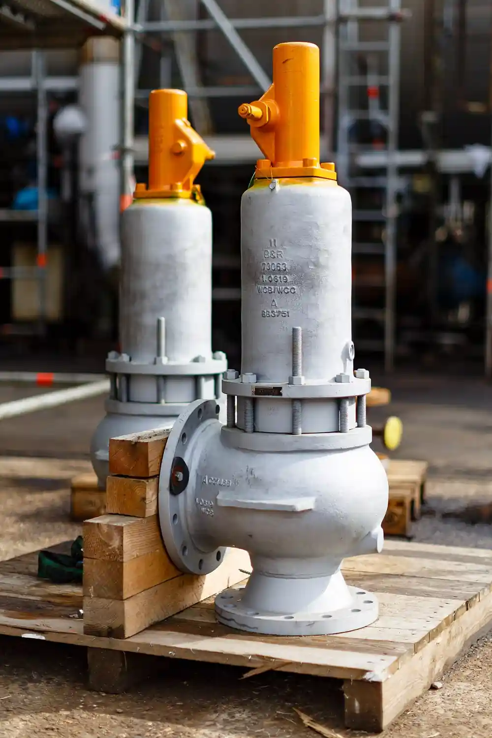
A changeover valve is a two-position switching fitting installed between two safety relief valves connected in parallel, so that one relief valve stays in service over the protected equipment while the other is isolated, vented, and opened for inspection, reseating, or replacement without a plant shutdown. The body joins one common inlet from the pressure system to two outlets, each feeding one safety relief valve, and a linked pair of quarter-turn plugs or balls opens exactly one flow path at a time. A mechanical interlock inside the linkage makes it impossible to block both outlets simultaneously, because an overpressure event during maintenance on one valve must still find an open relief path through the other. Sizes follow the relief valves they serve, commonly DN 25 to DN 200 with ASME Class 150 to Class 600 flanges, and the body is treated as part of the inlet piping when the installation is checked against the three percent inlet pressure loss rule.
Procurement engineers meet these valves in continuous-duty plants where taking a boiler, compressor, or reactor offline to reseat a chattering safety relief valve costs more than the valve itself: chemical and petrochemical pressure vessels, fired boilers under ASME Section I inspection regimes, compressor discharge scrubbers, and steam headers in paper mills. The decision this page settles is what the switchover body must guarantee on paper: how much inlet pressure loss it may add, how tightly the isolated side seals, what the interlock is proven to prevent, and whether the standby relief valve can be removed while the system remains pressurized. The answer lands as an RFQ line set covering set pressure of the pair, body class, inlet loss allowance, tightness class, interlock evidence, and bleed provisions, and every chapter below feeds that line set.
This page treats the changeover valve as a purchasing object: what the linked plug geometry does to inlet loss, how isolation tightness and interlock proof are documented, where ASME and API sizing language lands on the datasheet, and how body class, bleed ports, and maintain-under-pressure options combine into a defensible RFQ. It is written for engineers who issue purchase specifications, not for readers who want a brochure summary.
Chapter 1 / 06
What a Changeover Valve Is and What Is Being Decided
The problem being solved is older than the component. Every safety relief valve must be lifted, inspected, and reseated on a schedule set by the inspection code that governs the plant, and a single installed valve means a shutdown every time that schedule lands. Installing two relief valves in parallel solves the availability problem but creates a switching problem: the plant needs a fitting that connects either valve to the system while positively disconnecting the other, and that fitting must never leave both valves disconnected at once. The changeover valve is that fitting. Its common inlet bolts to the nozzle or header feeding the relief pair, its two outlets bolt to the inlets of the two safety relief valves, and its internal mechanism is a pair of ported plugs or balls driven by one shaft, arranged so that a 90 degree stroke transfers full flow from one valve to the other through an overlap region in which both paths are briefly open and never both closed.
What is actually being decided in this purchase is whether the switchover body can be trusted as part of the safety loop rather than as ordinary piping. Three guarantees carry that trust. First, flow capacity: the body must pass the full rated discharge of the in-service safety relief valve with a pressure loss small enough to respect the inlet loss limit, commonly held to three percent of set pressure at rated flow for compressible service per long-standing API 520 and API 521 practice, because inlet loss above that level can make a relief valve chatter and destroy itself. Second, isolation: the out-of-service side must seal tightly enough that the standby valve can be opened or removed without process fluid escaping through the dead leg. Third, interlock integrity: the linkage must be mechanically incapable of a both-closed state, and that incapacity must be documented by the manufacturer rather than asserted by a salesman.
Against its neighbors the component occupies deliberate ground. A three-way valve is a general process diverter built for mixing and routing duty, and while some published changeover bodies use three-way style geometry internally, a listed relief-valve changeover is a safety accessory with an interlock, documented inlet loss, and test evidence that a process three-way valve does not carry. A double block bleed valve isolates a line for maintenance in both directions with a vent between the seats, which is the isolation concept borrowed for the standby side, but it switches nothing between two destinations. The rupture disk lives upstream or downstream of individual relief valves as a second containment element, and a pressure vacuum relief valve protects atmospheric storage tanks against vacuum as well as overpressure, a different duty entirely. The changeover valve takes a narrow territory: it is the only component whose whole job is keeping one of two safety relief valves armed at all times.
Four references organize the datasheet. ASME Boiler and Pressure Vessel Code, Section VIII Division 1, sets the overpressure protection context in which the relief pair operates and Appendix M addresses installation practice, while Section I governs the boiler service variant. API Standard 520 Part II and API Standard 521 carry the installation guidance behind the inlet loss and backpressure limits that decide the body internals. API Standard 526 fixes the relief valve inlet flange drilling and face-to-face the switchover outlets must match, and ASME B16.34 governs the body wall and pressure temperature rating of the switching body itself. A datasheet that quotes none of these four is a price tag, not a specification, and a quotation for a changeover body without documented inlet loss at rated flow should be rejected on first reading.
The RFQ should also name the neighbors so the package checks out as a station. The safety relief valves themselves are ordered to their own specification with set pressure and capacity per ASME or EN practice; the changeover body is ordered to match their inlets in size, class, and material. Downstream of the relief valve outlets, discharge piping or a common header carries vented fluid away, built from the same gate valve, globe valve, ball valve, and pipe fitting families as the rest of the plant, with a butterfly valve sometimes replacing the gate on large discharge headers and a check valve kept out of relieving paths where backflow protection is handled elsewhere. On steam stations the relief pair usually sits downstream of a pressure reducing valve or let-down set, and the switchover body specification should reference that upstream control stage because chattering complaints are often traced there before the relief hardware is blamed. A rupture disk may be installed under one or both valves where process fluid would corrode the seat, and a back pressure regulator on a shared discharge header belongs in the station review because built-up backpressure acts on both relief valves regardless of which one the switchover body has armed. A needle valve serves the gauge and transmitter takeoffs, and a pressure gauge or pressure transmitter on the inlet header gives operations the reading that confirms which valve is in service. No isolation valve ever belongs in the inlet path of either relief valve, because the changeover body is the only switching element whose interlock is designed for this duty. Stating the whole station in the RFQ lets one supplier check flange drilling, materials, and class compatibility across the package in a single pass.
Chapter 2 / 06
How the Linked Plug Pair Switches Without Blocking Relief
The mechanism is best understood as two valves with one brain. Inside the body, two ported closure elements sit in the two outlet channels, each aligned with its safety relief valve inlet. A single shaft, extended through the bonnet to a hand lever, gear, or actuator, rotates both elements together. In position A, the left channel is fully open and the right channel is fully closed against its seat; in position B, the arrangement is reversed. Between the two end positions the ports pass through a designed overlap: as the left port begins to close, the right port has already begun to open, so at no shaft angle does the mechanism present a closed-to-both state. That overlap is the mechanical interlock in its purest form, and manufacturers deepen it with features such as lost-motion linkages, sequential cam profiles, or wedge interlocks that positively prevent both-closed assembly even if a seat is damaged during stroking.
Inlet pressure loss is the performance number that decides whether the body may be used at all. When the in-service relief valve flows at rated capacity, the switchover body sits directly in the inlet stream, and every elbow, port reduction, and seat pocket in it adds pressure drop upstream of the valve. Sizing practice for relief installations holds the total non-recoverable inlet loss at rated flow to three percent of set pressure, and the changeover body must be budgeted inside that allowance together with the inlet nozzle and piping. Manufacturers publish flow coefficients or direct pressure loss figures for each size, and a body with published loss of one percent at rated flow leaves two percent for piping, while a body tested at four percent makes the whole installation non-compliant before the first elbow is counted. Buyers migrating from single valve installations routinely underestimate this: the switchover body is not a fitting, it is a calculated pressure drop in series with the protected equipment.
Tightness of the isolated side is the second number. While one valve is in service, the other outlet channel is held closed by its plug or ball against full system pressure, and the leakage across that seat decides whether the standby valve can be safely opened. Practice follows the seat leakage classes of API 598 and EN 12266: a soft seated design with an elastomer or PTFE insert can reach visually bubble-tight classes suitable for taking the dead leg off, while a metal seated design in high temperature or sour service typically tests to a defined allowable rate that the site must accept in writing. The body also carries a bleed provision on the isolated side, either a drilled vent port or a small vent valve piped to a safe location, so the trapped pocket between the closed seat and the standby valve inlet can be depressurized before the flange is broken. That bleed is what turns a switchover body into a maintain-under-pressure package: with the system live, the standby valve is isolated, bled, unbolted, and lifted while its twin holds the plant protected.
Operation and indication close the design. Manual bodies switch with a lever or gearbox sized so one person can move them against full differential, and the shaft end carries a visible position indicator plus limit or proximity switches where the control system must know which valve is armed. Actuated versions add a pneumatic or electric actuator with a fail-safe position chosen by the site, though most installations keep switching manual precisely because the event that demands it, a planned inspection, is itself planned. Blowdown and chatter behavior of the in-service valve does not change when a proper body is added, provided the inlet loss stays inside budget; when a plant reports chattering after a switchover body is fitted, the first number to pull is the measured inlet loss at rated flow, and the second is the overlap timing of the plug pair if the switching was performed under flow.
A worked example fixes the arithmetic. Consider a vessel protected at 10 bar g set pressure by two safety relief valves, each sized for the full relieving case, connected through a DN 50 changeover body with published inlet loss of 1.2 percent at rated flow. The three percent budget at that set pressure is 0.3 bar; the body consumes 0.12 bar of it, leaving 0.18 bar for the inlet nozzle and straight pipe. If the same station were built with a generic three-way diverting valve whose published loss is 3.5 percent, the installation would exceed the limit through the switching element alone, and the chattering that follows would be predictable from the datasheet rather than mysterious in the field. The chapter four table carries these checks as rows, and chapter five turns them into RFQ lines.
Chapter 3 / 06
Types, Construction, and Duty Boundaries
Three body architectures cover the catalogs. The twin plug design uses two ported cylindrical plugs in one chest, the classic European construction used under steam and process vessels, favored for its robust metal seats and compact inline layout. The twin ball design uses two characterized balls sharing a shaft, the construction behind modern short-stroke switchover bodies such as the Baker Hughes Consolidated SafeSwitch family launched in late 2026, which packages the pair with an engineered overlap and integrated bleed in a body sized to API Standard 526 relief inlets. The flow-splitter design is a compact Y or cross casting with a single rotating disc or barrel that alternately uncovers the two outlet channels, used where headroom above the relief valves is tight. Within each architecture the buyer still chooses seat construction, materials, and the operation package, and those choices carry more warranty weight than the architecture name.
Seat construction sets the tightness and temperature envelope. Soft seats of PTFE or filled PTFE hold near bubble-tight isolation on the standby side across the common process range to about 200 deg C and make the maintain-under-pressure sequence clean. Metal seats of stellite or 13 chrome overlay run to 400 deg C and beyond in saturated and superheated steam and sour gas, at a defined leakage rate per API 598 or EN 12266 that must be accepted in the specification rather than discovered at the first inspection. For installations where the standby valve must be removed under pressure, the body adds a double block and bleed arrangement on the isolated channel: two seats in series with the bleed port between them, so a single scratch on one seat does not pass live process to the open flange. That arrangement borrows the isolation logic of a double block bleed valve but exists here only in the standby channel, never in the in-service flow path.
Materials follow the relief valves they serve. Standard bodies are WCB or LCC carbon steel for utility steam and hydrocarbon service, CF8M or CF3M stainless steel for chemical duty, and duplex or super duplex for high chloride and offshore packages, with trim in 316 or 17-4 PH and seats overlaid where sour service applies under NACE MR0175 and its ISO 15156 successor. Flanged ends dominate, matched to ASME B16.5 Class 150 to Class 600 or the EN 1092 PN16 to PN100 equivalents, though butt-weld ends appear on high class steam stations. A body ordered with materials lighter than its relief valves, a carbon steel changeover under stainless valves on a corrosive stream, fails on the same corrosion logic the valve specification already settled, and the mismatch usually surfaces first as seat damage on the standby side where condensate sits.
Boundaries are worth stating bluntly. This valve never substitutes for the relief device: capacity comes from the safety relief valve, and the changeover body only routes. It is not a process diverter for routing product between lines; that duty belongs to a three-way valve or dedicated diverter hardware selected for mixing and flow control, with no interlock evidence at all. It does not provide overpressure protection during switching by itself; the overlap geometry guarantees the in-service valve stays connected, and if the plant insists on switching under full relieving flow, the overlap timing and seat materials must be reviewed with the manufacturer for that specific event. And if the installation cannot tolerate any switching, a single relief valve with a rupture disk combination and a documented shutdown remains the honest answer, because a switchover station earns its premium only when inspection without shutdown has real value.
The duty map below consolidates the boundaries into one table a specifier can scan before writing the RFQ; it pairs common stations with the construction that survives them and the construction that generates callbacks.
Station
Suitable construction
Construction to avoid
ASME Section VIII vessel, clean gas, two SRVs
Twin ball body, soft seat, 1 percent class inlet loss
Generic three-way diverting valve with no loss data
Saturated steam header to 250 deg C
Twin plug, metal seat, steam-rated packing
PTFE seat at sustained top of range (creep)
Sour hydrocarbon with NACE MR0175 scope
LCC body, 316 trim, stellite seats, ISO 15156 materials
Standard WCB body with unlisted trim chemistry
Standby valve removal under pressure
Double block and bleed standby channel with vent
Single soft seat with no bleed port in the dead leg
Tight headroom over the relief pair
Y pattern flow splitter body
Twin ball body with tall lever and indicator
Remote or unmanned station
Actuated body with limit switches and SCADA point
Bare lever with no position feedback
Switching required under relieving flow
Manufacturer-reviewed overlap timing and seats
Any body not qualified for switching under flow
Inspection value too low to justify switching
Single SRV with rupture disk and planned shutdown
Switchover premium spent on a duty that never switches
Chapter 4 / 06
Key Specification Parameters
The table below decodes the datasheet lines that decide whether a quoted switchover body matches the station. Each row is a purchase defining parameter; the paragraphs after the table explain what to demand and what a weak answer looks like.
Attribute
Typical range or options
What it decides
Nominal size
DN 25 to DN 200 matching SRV inlets per API 526
Flange drilling, body rating, and the inlet loss at rated flow
Pressure class
ASME CL150 to CL600; PN16 to PN100 equivalents
Body rating per ASME B16.34 and the set pressure ceiling
Inlet loss at rated flow
0.5 to 1.5 percent family for engineered bodies
Compliance with the 3 percent inlet loss budget of the station
Isolation tightness
Soft seat near bubble tight; metal seat to API 598 / EN 12266 rate
Whether the standby dead leg can be opened safely
Interlock evidence
Overlap geometry plus mechanical interlock, documented
Proof that both-closed is impossible, demanded in writing
Bleed provision
Vent port or double block and bleed on the standby channel
Depressurizing the dead leg before breaking the flange
Lever, gear, pneumatic or electric actuator, fail position
Switching effort, remote stations, and position feedback
Position indication
Local indicator plus limit or proximity switches
Control system knowledge of which SRV is armed
Temperature rating
Soft seat to 200 deg C; metal seat to 400 deg C and above
Seat compound and derate at sustained heat
The inlet loss row deserves a paragraph of its own because it is the row most often blank. A body quoted without a pressure loss figure at the rated relieving flow of the connected safety relief valve cannot be budgeted into the three percent allowance, and accepting it transfers an unquantified risk onto the relief performance of the plant. Demand the figure at the actual rated flow coefficient of the valve pair, not at an arbitrary reference flow, and demand the test basis behind it. Where two suppliers differ by half a percent, the difference is real money in pipe sizing: at the margins, the lower loss body can let a station keep a shorter inlet run and still comply.
The interlock and bleed rows together decide whether the maintain-under-pressure sequence is a procedure or an incident. Ask for the manufacturer statement that the mechanism cannot block both outlets, the shaft angle versus port opening diagram that shows the overlap, and the bleed arrangement drawing for the isolated channel. The comparison table below compresses the operation and evidence decisions into the form a specification meeting can argue from.
Evidence demanded
Strong answer
Weak answer
Inlet loss at rated flow
Tested figure with flow basis, per size
Low pressure drop claim with no number
Both-closed prevention
Geometry statement plus interlock description
Operator training instruction instead of hardware
Standby tightness
API 598 / EN 12266 class stated for the seat pair
Tight general claim, no class or test basis
Bleed on standby channel
Vent valve or port with piping note
None; mechanic cracks a flange to vent
Position feedback
Two limit switches wired to DCS point
Paint marks on the lever
Sour qualification
NACE MR0175 / ISO 15156 material letter
Stainless steel is fine for everything
The actuation row closes the specification. Manual lever operation remains the default because switching is planned and infrequent, and a lever with a lockable handle prevents casual operation. Gear operators serve the larger sizes where torque demands it. Actuated bodies suit unmanned stations and installations where the inspection procedure is scripted into the control system, and the actuator fail position must be chosen deliberately: most sites choose fail-to-either-open-position rather than fail-last, so that a loss of power never leaves the mechanism mid-stroke in its overlap region. The quotation that quotes the body and leaves switching effort, indication, and lockout as an exercise is not a complete quotation.
Chapter 5 / 06
Selection Decision Factors and RFQ Language
The decision sequence is short enough to run as a checklist in a specification meeting, and each step eliminates a class of quotations before price comparisons begin.
Confirm the station economics: if inspection downtime is cheap, a single safety relief valve with a planned shutdown beats any switchover premium.
Fix the relief valves first: set pressure, overpressure basis, rated capacity and inlet size per API 526 or the EN equivalent, because the changeover body is dimensioned from them, never the reverse.
Budget the inlet loss: reserve the three percent allowance across nozzle, pipe, and body, then demand the body figure at rated flow and reject quotations without one.
Set the temperature and fluid envelope, then pick the seat: soft seat for clean service to 200 deg C, metal seat for steam and hot gas, double block and bleed standby channel where removal under pressure is planned.
Verify the interlock evidence: overlap diagram and manufacturer statement that both-closed is impossible, in writing, referenced in the purchase order.
Choose operation and indication: lever or gear for attended stations, actuator with limit switches and a chosen fail position for remote ones, lockable handle everywhere.
Match materials to the stream, including NACE MR0175 scope where sour, and confirm flange drilling against the relief valve inlets before order, not at delivery.
Fix the verification evidence: body test per API 598 or EN 12266, seat leakage certificate, material certificates EN 10204 3.1, and the inlet loss test basis.
Against neighboring component types, the comparison a specifier actually needs runs as follows, and it belongs here in the selection chapter rather than in the page title. A process three-way valve routes flow between destinations and has no interlock, no isolation class, and usually no published relieving-flow loss, so it is not a substitute even when the port pattern looks similar. A dedicated diverter or selector valve in hydraulic and process service switches between circuits under pressure but is built for continuous duty rather than safety loop integrity. A double block and bleed assembly provides the isolation half of the story and nothing about switching. The relief-valve changeover body wins when the plant needs the combination in one certified package: a documented both-open overlap, an isolated side with a bleed, and inlet loss engineered for relieving flow. Choose the package the inspection code needs, not the fitting a supplier has in stock.
The application map below turns that comparison into a table the project file can carry.
Application
Construction to specify
Check before order
Petrochemical vessel, 100 percent spare SRV
Twin ball body, soft seat, limit switches
Inlet loss at rated flow against 3 percent budget
Power boiler continuous blowdown header
Twin plug, metal seat, gear operator
Steam temperature derate and packing class
Offshore sour separator
Duplex body, NACE trim, actuated
ISO 15156 material letter and CI test basis
Compressor discharge scrubber
Inline twin plug with vent port
Pulsation effect on seat tightness with vendor
Pharma clean steam, inspections scripted
Stainless body, soft seat, electropolished bore
Drainability and crevice-free seat design
Legacy station retrofit under existing SRVs
Body matched to API 526 inlets, face-to-face checked
Nozzle loads and added height on relief piping
The RFQ block should be written once and reused. A complete block reads: quantity, inlet size, and class matched to the relief pair; set pressure of both safety relief valves and the overpressure basis; fluid, maximum temperature, and sour service scope; required body inlet loss at the rated flow coefficient of one valve, with the test basis; isolation tightness class for the standby channel per API 598 or EN 12266; interlock statement and overlap evidence demanded by reference; bleed arrangement on the isolated side, vent connection size and routing note; whether standby valve removal under pressure is intended; body, trim, and seat materials with NACE MR0175 or ISO 15156 scope where applicable; operation, lever or gear or actuator with fail position, lockable handle, and limit switch count; end details, flange drilling per ASME B16.5 or EN 1092, face-to-face against existing spools; and the certificate set, body test, seat leakage test, material certificates EN 10204 3.1, and the inlet loss figure on letterhead. A quotation returned without the inlet loss figure or the interlock statement is incomplete at any price.
Chapter 6 / 06
Installation, Standards, Failure Modes, and Maintenance
Installation quality decides whether the station reaches its designed protection level. Mount the body with the shaft accessible and the position indicator visible from grade, because the switching operation is part of the inspection procedure and operators must read which valve is armed without climbing. Support the relief valve discharge piping independently so the switchover body carries no nozzle loads it was not designed for; a twin valve station doubles the weight hanging over the inlet nozzle, and the added height of the body plus two safety relief valves is the first thing the structural check must cover. Pipe the standby channel bleed to a safe location, typically the discharge header or flare rather than grade, because the pocket it drains holds live process at system pressure. Torque flange bolts to the supplier table in a cross pattern, and after assembly verify with the system depressurized that the mechanism strokes freely through both positions and stops positively at each end.
Commissioning practice protects the interlock and the seats. Stroke the body empty before first fill and confirm the overlap behavior by watching the port openings through the open standby outlet where the design allows; some manufacturers supply a travel versus opening diagram that commissioning can sign against. With the system at working pressure and no flow, perform one supervised switch and verify the standby side holds with the bleed closed, then open the bleed and confirm the pocket depressurizes cleanly. Record the shaft torque needed; a body that needs meaningfully more torque at first fill than it did empty is telling you something about seat loading, and the number belongs in the maintenance file as the baseline for condition trending. Where limit switches are fitted, prove both positions to the control system before the station is handed over, not after the first inspection cycle.
The standards set the verification frame. ASME Section VIII Division 1 and its Appendix M carry the installation context for the relief pair, and Section I governs the boiler variant; API 520 Part II and API 521 hold the inlet loss and installation practice the body is budgeted against; API Standard 526 fixes the relief valve inlet geometry the outlets match; ASME B16.34 rates the body wall and pressure temperature by class; and API 598 or EN 12266 define the seat leakage testing quoted on the certificate. Sour scope rides on NACE MR0175 and ISO 15156. A specification that cites these by name in the RFQ block transfers the burden of proof to the supplier, which is where it belongs, and a changeover body sold without any reference to them should be treated as unlisted hardware in a listed station.
Failure modes in service follow a short and predictable list. Seat wear on the standby side: the isolated seat holds full differential continuously and its leakage class drifts upward with time, detected at the supervised switch by process appearing at the bleed; reseating or seat replacement is scheduled maintenance, not an emergency. Stem packing leakage: the shaft seals against full system pressure whenever the body is at rest, and high temperature service erodes packing volume; adjust or replace on the torque trend. Binding and torque growth: corrosion products or paint on the shaft, misalignment from pipe loads, or seat swelling can raise switching torque until the lever or gear cannot move it, and the failure is usually gradual, which is why the commissioning torque baseline earns its place in the file. Damage from switching under relieving flow: overlap regions are designed for low or zero flow switching, and an emergency switch taken while the valve is discharging can wash or gall the seats; where the procedure requires this, it must be qualified with the manufacturer in advance. Interlock damage from forced operation: never hammer the lever, and never defeat the stops; a bent interlock that still blocks both-closed is acceptable, one that jams the mechanism mid-stroke is a station-wide protection outage.
Maintenance intervals scale with switching frequency rather than calendar time. A station switched monthly for relief valve rotation deserves a packing check and supervised switch every cycle and an internal seat inspection at every relief valve shop visit, riding the same schedule as the valves it serves. A station switched once a year stretches to an annual stroke, torque, and bleed verification, with internals opened only on symptom or at the multi-year relief valve overhaul. Every supervised switch should capture shaft torque, bleed behavior, and switch indication, and those three numbers, trended across years, are the entire health record of the component. None of these checks costs a tenth of one unplanned protection outage, and every one of them produces a number the next RFQ can use, which is how a purchasing file gets smarter instead of just older.
FAQ
What does a changeover valve do on a pair of safety relief valves?
It is a two-position body between two parallel safety relief valves that keeps one valve connected to the protected system while positively isolating the other for inspection or replacement, without a shutdown. A linked plug or ball pair opens exactly one flow path at a time through an overlap where both are briefly open, so the system never loses relief protection during switching.
How much inlet pressure loss can I allow through the changeover body?
Relief installation practice holds total non-recoverable inlet loss at rated flow to three percent of set pressure, and the body must be budgeted inside that allowance together with the nozzle and piping. Engineered bodies publish figures around 0.5 to 1.5 percent at rated flow; demand the number for your size and the rated flow coefficient of the connected valve, and reject quotations that do not carry it.
Can both relief valves end up isolated at the same time?
Not with a properly constructed body. The port geometry passes through an overlap in which both outlets are open during the stroke, and manufacturers add mechanical interlocks such as sequential cams or lost-motion linkages so a both-closed state cannot be assembled even with a damaged seat. Ask for the overlap diagram and the both-closed impossibility statement in writing and reference them in the purchase order.
What tightness applies to the isolated standby side?
Soft seats reach near bubble-tight classes that allow the dead leg to be opened cleanly, while metal seats for steam and hot gas test to a defined allowable leakage rate per API 598 or EN 12266 that the site accepts in writing. For standby valve removal under pressure, specify a double block and bleed arrangement on the standby channel so a single seat defect cannot pass live process to the open flange.
Can I remove the standby relief valve while the system is pressurized?
Yes, when the body provides that capability: switch so the standby side is isolated, open the bleed to depressurize the pocket between the closed seat and the valve inlet, verify zero pressure at the bleed, then break the flange and lift the valve while its twin stays in service. The bleed arrangement and seat class must be specified for this sequence at purchase, because a body without a vent port leaves trapped pressure in the dead leg.
What sizes and pressure classes are available?
Bodies match the safety relief valve inlets they serve, commonly DN 25 to DN 200 with ASME Class 150 to Class 600 flanges, or EN 1092 PN16 to PN100 equivalents, with butt-weld ends on some high class steam stations. Materials run from WCB and LCC carbon steel through CF8M stainless to duplex for offshore and high chloride duty, with NACE MR0175 and ISO 15156 scope where the stream is sour.
Should the changeover body be manual or actuated?
Manual lever or gear operation remains the default because switching is planned and infrequent, and a lockable lever prevents casual operation. Actuated bodies with limit switches suit unmanned stations and scripted inspection procedures; choose the actuator fail position deliberately, typically to an end position rather than last, so a power loss never parks the mechanism mid-stroke in its overlap region with neither valve fully connected.