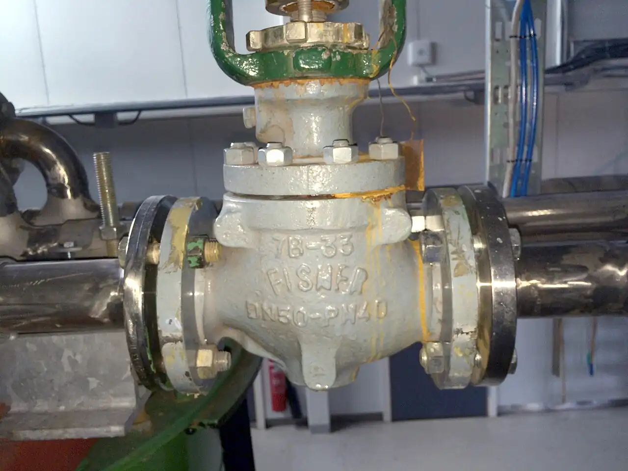
A desuperheater is a device that injects a finely atomized stream of high purity water into superheated steam, so that the water evaporates inside the line and cools the steam toward saturation. The purpose is steam temperature control: boilers and pressure reducing stations deliver steam tens or hundreds of degrees above the saturation temperature, and much of the downstream equipment, heat exchangers, turbines, sterilizers, drying cylinders, wants that superheat trimmed to a stated margin. The target outlet condition is an approach of 3 to 15 deg C above saturation at line pressure, and the water must be fully evaporated before the temperature sensing point; those two sentences contain most of the engineering on this page.
Procurement engineers meet these devices on turbine bypass and crossover attemperation in power plants, on pressure reducing valve stations where letdown steam leaves heavily superheated, on process steam headers conditioned to near saturation before heat transfer duty, and on clean steam systems feeding sterilizers. The decision this page settles is narrow and practical: which atomization type and turndown the load demands, how much absorption distance the pipe run can give, what spray water pressure and quality the nozzles need, and which control hardware closes the loop. The answer lands as an RFQ line set, steam conditions, approach, water spec, type, materials, and control package, and every chapter below feeds that line set so the station is bought, not hoped for.
This page treats the desuperheater as a purchasing object: what spray attemperation physics demands of turndown and distance, which of the five hardware types earns its premium on which load, what the spray water system must deliver at the nozzle, how the control loop is assembled from real instruments, and how the known failure modes write themselves into the specification. It is written for engineers who issue purchase specifications, not for readers who want a brochure summary.
Chapter 1 / 06
What a Desuperheater Is and What Is Being Decided
The operating principle is direct contact heat transfer. Water sprayed into superheated steam evaporates, and every kilogram of evaporation draws roughly 2,300 kJ out of the surrounding steam, which is superheat the steam can no longer carry. There is no heating surface, no fin, no separate coolant circuit: the steam is cooled by its own future condensate. The hardware variants on the market differ only in how they atomize the water and how wide a flow range they can cover while atomization stays healthy, and those two attributes, droplet size and turndown, explain nearly every price difference between competing quotations.
What is actually being decided in this purchase is four commitments made at once: an atomization type matched to the load swing, an absorption distance that fits the pipe run between the injection point and the first elbow or equipment nozzle, a spray water system that delivers the right pressure and purity at minimum load rather than at the pump discharge, and a control package that couples steam side measurement to water side actuation. A desuperheater bought as a welded nozzle alone is half a purchase; the water valve, the strainer, the transmitters, and the interlock decide whether the station works on the first startup or on the third attempt, and the RFQ language in chapter 5 assigns each of those items to a named supplier.
Boundaries against neighbors are worth one sentence each, with the full hardware comparison reserved for the selection chapter. A steam ejector spends high pressure steam to entrain vapor and create vacuum; it heats and moves fluids, while the desuperheater cools them, and the two devices share vocabulary and nothing else. A surface desuperheater, built as a shell and tube heat exchanger with steam on one side of the tubes and cooling water on the other, removes superheat without injecting anything, at the cost of a pressure vessel, a fouling surface, and a cooling water circuit of its own. Between those neighbors, spray attemperation occupies the economic middle: cheap hardware, demanding water chemistry.
Four reference frames organize the datasheet. Steam piping design follows ASME B31.1 for power service or ASME B31.3 for process service, and the desuperheater welds into that piping as an in-line component with its pressure rating carried by the pipe schedule and the weld details. Nozzle and connection flanges follow ASME B16.5 drilling. Where the desuperheater belongs to a turbine bypass train, the water cut-off and trip logic is assessed under IEC 61508 SIL concepts, and the proof test interval that the assessment assigns becomes a maintenance line item in chapter 6. Spray water chemistry follows the boiler or clean steam practice of the plant, EPRI or VGB cycle chemistry guidance in power service, and the silica limit belongs in the purchase order, not in a startup memorandum.
The desuperheater never works alone, and the RFQ should name its station. Upstream sits the steam source, a boiler header or a pressure reducing valve station, whose outlet superheat sets the duty. The water side carries a supply pump or condensate header, a strainer, a block valve, and the control valve that modulates injection. The steam side carries the measurement: steam flow, steam pressure, and the downstream temperature transmitter that closes the loop. Naming the whole station in the RFQ lets one supplier check flange drilling, gasket seating, instrument ranges, and water chemistry in a single pass instead of four arguments at delivery, and it exposes interface gaps, an atomizing steam connection nobody ordered, a drain nobody piped, while they are still line items.
Chapter 2 / 06
How Spray Attemperation Cools Steam
Sizing starts with an enthalpy balance that fits on one sheet. Each kilogram of spray water absorbs sensible heat up to the local saturation temperature and then its latent heat of vaporization, both taken from the steam; the steam gives up superheat at a specific heat near 2.1 kJ per kg per K. A worked example: steam at 10 bar absolute, 300 deg C, conditioned to 190 deg C, holds about 230 kJ per kg of superheat to shed, and each kilogram of condensate grade water takes roughly 2,350 kJ to heat and evaporate at that pressure. The water to steam mass ratio is therefore near 0.10, about 10 kg of water per 100 kg of steam, and the capacity line for the entire water system follows directly from that ratio at maximum steam flow. The ratio moves with pressure and approach, so the calculation is run at both ends of the load range before any hardware is named.
Evaporation time scales with the square of droplet diameter, which is why atomization is the technology of the whole device. Droplets well under 100 micron, produced by steam atomized nozzles, evaporate within a couple of metres at normal steam velocity; 300 to 500 micron droplets from a simple fixed cone can need most of 10 m of straight run, and some fraction of them still arrives on the pipe wall as a film. Steam velocity through the mixing section should sit around 15 to 40 m/s at operating load, with roughly 10 m/s as the practical floor: slower steam lets droplets rain out, faster steam erodes nozzles and liners and pushes the downstream hardware. Velocity, not pipe size, is the variable the process engineer actually controls at minimum load, which is where most carryover incidents begin.
The approach target and the absorption distance are coupled decisions. An approach of 3 to 15 deg C above saturation is the working band: closer than about 3 deg C and the last droplets cannot finish evaporating, because the superheat that drives their evaporation has been spent; at 15 deg C the downstream equipment receives control with generous margin and the hardware is cheap. The absorption distance, the straight pipe needed for full evaporation before measurement, runs from about 6 to 20 pipe diameters as a minimum depending on type, and 3 to 10 m in practice, with steam atomized types at the short end and fixed cone nozzles at the long end. The RFQ must state the distance actually available in the installed run, because physics does not negotiate with plot space, and a bend or a thermowell inside the absorption zone both disturbs evaporation and reads the wrong temperature.
The control loop is a delayed feedback loop with a strong feedforward case. The measured variable is steam temperature from a temperature transmitter mounted downstream of the full absorption distance, typically 5 to 10 m from the injection point, in a straight, insulated run. The manipulated variable is spray water flow through a control valve on the water line. Because transport delay between valve and sensor invites oscillation, well built stations add feedforward from steam flow, classically an orifice plate flowmeter on the steam line with its differential transmitter, and compute the saturation reference from a pressure transmitter on the same line, so that the controller holds an approach margin rather than a raw setpoint that means something different at every load. In DCS practice the loop is a PID with feedforward and anti windup, tuned against the measured transport delay, and the tuning session is part of commissioning, not part of the purchase.
The spray water system has to deliver at the nozzle, not at the pump. Spray types need roughly 1.5 to 5 bar more pressure than the steam line at maximum injection flow, after the losses of the supply piping, the Y strainer that protects the nozzles, and the control valve itself have all taken their share. The source is normally condensate or demineralized water: boiler feedwater taken from the feed header, a condensate return header, or a dedicated demineralized skid on clean steam duty. A block valve upstream of the control valve, with a drain between the two, enables the seat leak test that chapter 6 schedules, because a water valve that dribbles into idle hot steam is a thermal shock machine waiting for its shift.
Water quality is a steam purity decision in disguise. Every kilogram of spray water becomes steam, and its dissolved solids travel with it: silica deposits on turbine blades, salts lay scale in downstream piping and heat exchanger passages, and oxygen scavenger residuals carry into the header and change its chemistry. The usual specification floor is boiler feedwater grade, with the silica limit set by the turbine owner or the process, and demineralized water for anything feeding a condensing turbine or a sterilizer. The honest alternative is the surface desuperheater mentioned in chapter 1, which injects nothing but pays with a pressure vessel and a fouling surface; on most process stations, clean water is cheaper than hardware, and on turbine duty it is mandatory.
Chapter 3 / 06
Types, Construction, and Duty Boundaries
Five hardware types cover the market, distinguished by atomization method and turndown, and the table at the end of this chapter compresses them into one view a specifier can scan. The types share a mechanical family: a nozzle or element set welded or flanged into the steam line, a water connection, sometimes an atomizing medium connection, and optionally an internal wear liner in the mixing zone where droplet density is highest. What differs is how the water is broken into droplets, how far the flow can swing while atomization stays healthy, and how much straight pipe the evaporation needs after it.
The fixed cone spray desuperheater is the entry product: one or a few fixed geometry nozzles inserted through a weld boss, spraying into the steam stream. At design flow it works well, it is cheap, and it installs in an afternoon. Its turndown is limited to about 1:3 because a fixed orifice needs pressure differential to atomize, and at low flow it dribbles large droplets instead of spraying them. Plants patch the limitation with staged nozzle groups cut in through small isolation valves, accepting mechanical complexity in exchange for range, and the staging logic belongs in the control narrative if it is bought.
The variable area spray type, the Spirax Sarco DA class, moves a profiled plug inside the water nozzle so that the annular opening varies with travel: atomizing velocity is preserved across a much wider water range, and turndown reaches 1:10 to 1:20. The plug and seat are precision parts in 316 or hardfaced stainless, driven by the same positioner hardware as any control valve. This is the workhorse of process steam conditioning, where the load swings shift to shift and the header must stay within a stated approach band of saturation for the heat transfer equipment downstream.
The venturi multi nozzle type, the Spirax Sarco DAC class, arranges several small nozzles discharging into a venturi mixer section: the steam accelerates through the throat and shears the spray mechanically, with no auxiliary medium at all. Turndown is moderate, about 1:5 as a family figure, absorption distance sits in the middle of the range, and the all welded construction tolerates high line pressure because everything lives inside a forged body. These units are common directly downstream of pressure reducing valve stations, conditioning letdown steam before it reaches users, and their lack of external services is exactly why they are chosen there.
The steam atomized desuperheater, the Emerson Fisher TBX-T class, admits auxiliary steam at a pressure higher than the line and shears the water at the nozzle face into droplets well under 100 micron. Atomization no longer depends on water flow, so turndown reaches 1:25 and beyond, and the absorption distance is the shortest of the family, which is why it fits the tight pipe runs of bypass stations. The price is the auxiliary steam connection, which must be dripped clean through a steam trap before use, and a small needle valve in the atomizing line for manual balancing during commissioning. This is the standard choice for turbine bypass duty, where load swings are violent, distance is short, and water carryover is catastrophic.
The attemperator closes the family as an integrated unit: a spray desuperheater with the water control valve built into the same body, so the injection element and the metering plug are designed, characterized, and tested together. Boiler interstage spray and compact bypass skids use this form. Buying integration removes one interface argument, and it fixes the valve characteristic, so the loop tuning belongs to one vendor; the same sentence is the argument against it on plants that prefer to keep valves inside their own spares and maintenance system, and both positions are legitimate as long as the RFQ states which one the purchase takes.
Type
Atomization method
Turndown family figure
Absorption distance guidance
Natural duty
Fixed cone spray
Fixed nozzle pressure differential
About 1:3
Longest, up to 10 m straight run
Steady loads, small stations
Variable area spray, DA class
Plug varies the annular orifice with travel
1:10 to 1:20
5 to 8 m class
Process steam conditioning
Venturi multi nozzle, DAC class
Venturi shear, no assist medium
About 1:5
3 to 6 m class
PRV station letdown conditioning
Steam atomized, TBX-T class
Auxiliary steam shear at the nozzle
1:25 and beyond
2 to 4 m class
Turbine bypass, tight pipe runs
Integrated attemperator
Spray element with built-in water valve
Per spray type
Per spray type
Boiler interstage, bypass skids
Chapter 4 / 06
Key Specification Parameters
The table below decodes the datasheet lines that decide whether a quoted desuperheater matches the duty. Each row is purchase defining; the paragraphs after it explain what to demand and what a weak answer looks like.
Parameter
Typical range or decision
What it decides
Steam flow range
Stated at maximum and minimum operating load, with the turndown ratio
Type selection and any nozzle staging
Inlet pressure and temperature
e.g. 40 bar at 350 deg C, at both loads
Body rating, weld details, and the saturation reference
Outlet target and approach
3 to 15 deg C above saturation at line pressure
Water ratio, atomization class, distance demand
Spray water pressure margin
1.5 to 5 bar above the steam line at maximum flow
Pump or header sizing and valve authority
Spray water quality
Condensate or demineralized, silica limit stated
Turbine and piping deposit behavior
Pipe size and straight run
Actual installed distance to the first obstruction
Whether the quoted type physically fits the run
Nozzle material
410, 316, 316L, or C276
Erosion and corrosion life at the spray zone
Liner
Welded wear liner in the mixing zone, high velocity service
Survival of the pipe wall where droplets are densest
The spray water rows deserve the most attention because they fail the most often. The pressure margin of 1.5 to 5 bar must exist at the nozzle at maximum flow, which means the supply calculation runs backwards from the steam line pressure through the control valve and the strainer, not forwards from a pump curve. On the water path, a Y strainer with a fine mesh, typically 100 to 200 mesh, protects small nozzles from scale and weld debris; header fed systems and larger stations add a basket strainer upstream for bulk capture during commissioning. A takeoff from a condensate header should sit above a condensate pot so that the draw is clean water rather than flash and dirt, and the takeoff nozzle is sized for the maximum water ratio from chapter 2, not for an average.
The control package paragraph should name each element and its owner. The water valve is usually a globe control valve sized for the injection range, with a cavitation review, because the drop from water header to steam line is often large and flashing is common. The steam side instruments are the temperature transmitter downstream, the pressure transmitter for the saturation reference, and a flow meter for feedforward, classically an orifice plate flowmeter with its differential transmitter. A solenoid valve or fast acting block valve in the water line, interlocked to steam flow or bypass position, stops injection when there is no steam left to evaporate it. Every interlock line in the RFQ should state who supplies it, the valve vendor or the control system contractor, because unowned interlocks are how stations flood during trips.
Materials follow steam chemistry and velocity. Nozzle internals in 410 stainless suit clean power cycle steam; 316 and 316L cover most process service; Alloy C276 appears where the steam carries chlorides or the spray water is aggressive. The mixing zone of high velocity lines takes a welded liner, typically 410 or 304 sheet, renewed at major outages, because unlined carbon pipe erodes at exactly the point where droplet concentration peaks. The nozzle flange and its companion drilling follow ASME B16.5, and the gasket at that joint is part of the pipe stress conversation, chosen for the steam temperature, not whatever the fitter had on the truck.
The signal chain table below consolidates the loop into the form a control engineer can argue from in a specification meeting, and it doubles as the ownership checklist for the RFQ.
Loop element
Hardware
What it contributes
Feedback
Downstream temperature transmitter
The measured outlet temperature, taken after full evaporation
Saturation reference
Pressure transmitter on the steam line
The saturation temperature that converts approach into a setpoint
Feedforward
Steam flow meter, often an orifice plate flowmeter
Water demand anticipation on load swings
Actuation
Globe control valve on the spray water line
The modulated water flow
Protection
Solenoid valve or fast block valve
Cuts water on loss of steam flow or bypass closure
Startup drainage
Steam trap and manual vents
Dry steam at the nozzle during warmup
Chapter 5 / 06
Selection Decision Factors and RFQ Language
The decision sequence below runs as a checklist in a specification meeting, and each step eliminates a class of quotations before any price comparison starts.
Fix the steam duty honestly: maximum and minimum flow, inlet pressure and temperature, outlet target and approach, stated at both ends of the load range.
Compute the water ratio at maximum and minimum load from the enthalpy balance in chapter 2, and state the required turndown that follows.
Measure the straight run available between the injection point and the first elbow, valve, or equipment nozzle, and compare it with the absorption distance each type demands.
Audit the spray water system: pressure at the nozzle at maximum flow, water quality with the silica limit, temperature, and source reliability across the operating year.
Choose the atomization type against turndown and distance, using the table in chapter 3, and write the type into the RFQ by name.
Specify the control package as a scope: valve, positioner, transmitters, feedforward, interlock, and the owner of each item.
Fix the verification evidence: water ratio calculation at both loads, absorption distance statement, spray test curves, and material certificates.
State the standards: ASME B31.1 or B31.3 scope, ASME B16.5 flanges, and the IEC 61508 SIL assessment where the bypass cut-off is safety rated.
Against the neighboring hardware, the comparison a specifier actually runs is total cost of temperature control, and it belongs here in the selection chapter. The surface desuperheater, a shell and tube heat exchanger with steam on the shell side, injects nothing and forgives dirty water, but it is a pressure vessel with a fouling surface and a cooling water circuit of its own, and it is priced accordingly. A plate heat exchanger serves close approach liquid to liquid duty, feedwater preheating and condensate subcooling around the steam system, and has no role in cooling steam inside a line; the two purchases interact only where the plate heat exchanger sets the spray water source temperature. In remote arid plants the turbine exhaust condenses in an air-cooled heat exchanger, and an air-cooled heat exchanger only rejects sensible heat economically, so the bypass desuperheater ahead of it still conditions the steam first; the same water-scarce logic drives that pairing on every dry-site project. Below ambient cooling is a chiller duty and never an attemperation duty: the desuperheater removes superheat and cannot cool anything under the local saturation temperature, and a process that genuinely needs cold fluid year round buys a chiller, not steam hardware. Downstream of a pressure reducing valve station the letdown steam arrives heavily superheated, and in most plant standards the desuperheater is bought as a pair with the safety relief valve that protects the low pressure header, one vendor package, one set of setpoints.
The application map below turns the selection logic into a table the project file can carry.
Application
Construction to specify
Check before order
Turbine bypass and crossover attemperation
Steam atomized type, 1:25 class, shortest distance, interlocked water cut-off
SIL scope, atomizing steam takeoff with its steam trap, velocity at peak bypass flow
PRV station letdown conditioning
Venturi multi nozzle or variable area type
Superheat after letdown at minimum load; safety relief valve setting on the low pressure header
Process header trim to near saturation
Variable area spray, 1:10 to 1:20
Approach band 5 to 10 deg C; spray water quality on long headers
Carryover risk to cylinders and traps; condensate handling after trim
Boiler interstage spray
Integrated attemperator
Valve characteristic data against boiler dynamics study
The RFQ block should be written once and reused. A complete block reads: steam flow at maximum and minimum operating load; inlet pressure and temperature; outlet target temperature with the stated approach; pipe size, schedule, and the straight run available to the first obstruction; spray water source, pressure at the nozzle, temperature, and quality with the silica limit; the atomization type by name with the required turndown; nozzle material and liner decision; the control package scope, including the control valve, temperature transmitter, pressure transmitter, feedforward flow meter, and the interlock solenoid valve with its owner; flange standard and drilling; and the verification deliverables, the water ratio calculation at both loads, the absorption distance statement, spray test curves, and material certificates to EN 10204 3.1. A quotation returned without the absorption distance statement is incomplete at any price, because it is the line on which the whole physics of the purchase stands.
Chapter 6 / 06
Installation, Standards, Failure Modes, and Maintenance
Installation decides whether the quoted absorption distance is actually delivered. Mount the unit in a straight horizontal run where the pipe layout allows, with the spray directed along the steam flow and at least the vendor stated distance to the first bend, valve, or instrument thermowell; vertical downflow runs are acceptable where layout forces them, because gravity then helps the droplets travel with the steam. Warmup condensate at the injection point must have a drain path: at the line low point a condensate pot collects warmup drainage and passes it to the steam trap, with a warmup vent, a needle valve cracked open during warmup, at every high point that can collect air. Insulate through the mixing zone and the sensing run: heat loss to atmosphere is superheat the spray water no longer has to remove, and an uninsulated sensing point reads a temperature the steam left behind at the wall.
Commissioning verifies three things in order. Water side: flush the supply line to the strainer before the nozzles ever see flow, then prove the pressure margin at maximum injection with the control valve open to the bypass station. Steam side: warm the line with condensate drained at every low point, and verify dry steam at the nozzle before any water is admitted. Loop: stroke the water valve against the downstream temperature transmitter in manual, record the transport delay between a valve step and the first sensor movement, then tune with feedforward active and file the response curve. The vendor bench curves, spray pattern and capacity, should be compared against the field behavior while the unit is still under warranty, because that comparison is the only leverage the buyer will ever have on an absorption distance claim.
The standards frame is short and citable. ASME B31.1 governs power piping and the weld-in details of the desuperheater in power service; ASME B31.3 covers process plants; ASME B16.5 fixes the flange drilling at the nozzle, water, and instrumentation connections. Turbine bypass trains carry an IEC 61508 SIL assessment on their cut-off functions, and the proof test interval in that assessment becomes a scheduled maintenance action with a record. Water chemistry follows the boiler or clean steam practice of the plant, EPRI or VGB cycle chemistry guidance in power service, and the silica limit for the spray water belongs in the purchase order wherever a turbine or a sterilizer can see the resulting steam.
Failure modes in service follow a short and predictable list. Water carryover heads it: an undersized absorption distance, or atomization that collapses at low load, sends unevaporated droplets downstream, where they erode bends, quench thermowells, and reach turbines as blade eating wet steam. Nozzle erosion from wet steam and solids enlarges the orifice until the water ratio drifts and the loop hunts. Scale from marginal water quality plates the mixing zone, the nozzles, and the downstream pipe, and the first symptom is usually a rising approach error rather than anything visible. Control hunting at low load is the turndown limit announcing itself, and the fix is type selection, not tuning. Thermal shock from a leaking water valve dribbling into idle hot steam splits liners and welds; the block and drain arrangement between block valve and control valve exists so that the leak can be detected and drained while the station is out of service. Liner wear at high velocity, finally, is consumption rather than accident, and the inspection plan treats it as a wear part with a thickness record.
Maintenance intervals scale with duty severity. Quarterly: proof test the solenoid valve and the water cut-off interlock where the SIL assessment demands it, and walk down drains and vents. Yearly: stroke the control valve and leak test its seat through the block and drain, sample the spray water against the purchase specification, and clean the Y strainer screen, opening the basket strainer on header fed systems at the same visit. Each major outage: pull nozzles and measure orifice size against new, inspect the liner for thinning and cracking, verify the temperature transmitter and pressure transmitter calibrations, and re-run the loop response curve against the commissioning record. A water valve that passes a seat test and a nozzle within wear limits costs a shift to verify; carryover through a turbine, or a quenched sterilizer load, costs the year, and the difference between the two is the schedule in this paragraph.
FAQ
What approach to saturation should the outlet target carry?
Plan the control target 3 to 15 deg C above the saturation temperature at line pressure, with 5 to 10 deg C the common band. Closing to within 3 deg C demands fine atomization, generous absorption distance, and dry spray water. Driving the outlet to saturation inside the pipe risks unevaporated water carryover, which erodes bends and destroys turbine blades. The temperature margin is insurance, and its price is a small amount of residual superheat.
Which desuperheater type covers the widest turndown?
Steam atomized desuperheaters lead the field with turndown ratios of 1:25 and better, because auxiliary steam shears the water into droplets well under 100 micron even at low water flow, so evaporation stays complete through violent load swings. Variable area designs follow at 1:10 to 1:20. Fixed cone nozzles manage about 1:3 and belong on steady loads. Turndown claims must always be read against the steam side velocity limit as well.
What spray water pressure does the unit need?
Spray types need the water header roughly 1.5 to 5 bar above the steam line pressure at maximum injection flow, not just at the pump discharge: the margin must survive the supply piping, the strainer, and the control valve together. Steam atomized types trade part of that margin for an auxiliary steam supply at higher pressure still. Verify the available differential at minimum steam load, where line pressure after a letdown is highest.
What water quality is acceptable for spray water?
Use condensate or demineralized water. Every kilogram of spray water flashes into the steam and carries its dissolved solids with it, so silica and salts concentrate on downstream surfaces, and turbine blade deposits begin life as marginal spray water. Boiler feedwater quality is the usual specification floor, with the silica limit stated by the turbine owner. A surface desuperheater avoids injection entirely but costs more and adds its own fouling surface.
Where should the outlet temperature be measured?
Downstream of the full absorption distance, typically 5 to 10 m from the injection point depending on type and steam velocity. Measuring sooner reads a mixture of dry steam and evaporating mist, and the loop chases a signal that moves with load. The temperature transmitter should sit in a straight, insulated run, at least 10 pipe diameters from bends, with the saturation reference taken from a pressure transmitter on the same line.
Why does the outlet temperature oscillate at low load?
Usually a turndown limit. When steam flow falls below the water nozzle range, the control valve rides nearly closed and then sprays in slugs: the droplets are too large to evaporate in the available distance, and the outlet temperature swings wet and dry. The remedies are a variable area or steam atomized unit with wider range, staged nozzles, or feedforward from steam flow so the loop anticipates instead of reacting.
Can the outlet be controlled to exactly saturated steam?
Not in the pipe, and no specification should ask for it. Contact evaporation needs superheat to finish the last droplets; at zero approach, residual water wets the line, thermal shock loads downstream hardware, and the temperature measurement loses its reference. Deliver steam a few degrees above saturation and take the final approach inside the process equipment, where wetting is harmless or intended by design.