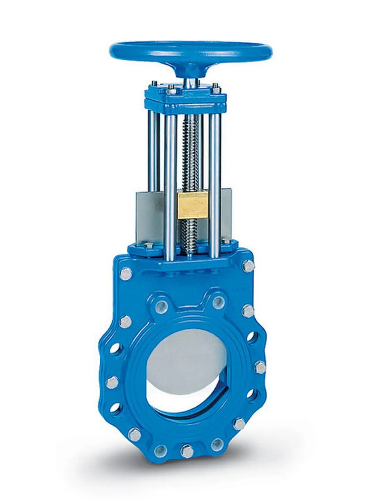
A flush bottom valve is a drain valve mounted in the bottom nozzle of a tank, kettle, or reactor so that its sealing surface sits flush with, or a fraction below, the vessel floor. Nothing projects into the vessel and no sump hangs beneath it: when the valve opens, the batch drains completely, with no heel, no dead volume, and no pocket where product can hang up, crystallize, or contaminate the next batch. The same hardware answers to the names tank bottom valve and bottom outlet valve in supplier catalogs, and it is bought as a weld-in pad or as a flanged body with ASME B16.5 class 150 or class 300 faces, in sizes from DN 25 to DN 200 in the common family spread.
Procurement engineers meet these valves where drain completeness carries money: polymer and resin reactors that must empty before the batch gels, crystallizers where a leftover heel seeds the next batch with the wrong crystal size, slurry tanks in mining and flue gas desulfurization duty, and sanitary food and pharma vessels that must drain to a cleanability standard. The decision this page settles is narrow and practical: ram or piston closure against a rising disc, the sealing plane in the vessel nozzle or in the valve body, the outlet angle at 45, 60, or 90 degrees, and the actuation, seat class, and purge hardware that go with the choice. The answer lands as an RFQ line set, and every chapter below feeds that line set.
This page treats the flush bottom valve as a purchasing object: what ram and piston closure changes in slurry and crystallizing duty, how seat in vessel and seat in body builds trade drain completeness against service access, what the outlet angle and shutoff class rows of a datasheet must state, and how actuation, purge, and CIP hardware combine into a defensible RFQ. It is written for engineers who issue purchase specifications, not for readers who want a brochure summary.
Chapter 1 / 06
What a Flush Bottom Valve Is and What Is Being Decided
The defining dimension of a flush bottom valve is the position of its sealing plane. The valve welds or bolts into the bottom nozzle of a tank, kettle, or reactor, and its seat surface sits level with, or just below, the vessel floor. A conventional drain valve bolted under the same nozzle leaves a sump behind: nozzle bore plus body cavity typically traps 0.5 to 3 litres on a DN 50 to DN 100 outlet, and that sump is where the batch leaves its heel. Product hangs in the pocket, crystallizes, skins over, or cultures, and the next batch inherits all of it. The flush bottom valve exists to delete that volume, and every construction choice on its datasheet serves that one purpose.
What is actually being decided in this purchase is four commitments. The first is the closure type: a ram or piston that descends into the seat, or a disc that lifts off it. The second is the sealing plane location: a seat ring welded into the vessel nozzle, or a seat carried in the valve body one joint below. The third is the outlet angle: 45, 60, or 90 degrees, which fixes the routing under the vessel. The fourth is the actuation and sealing package: cylinder or handwheel, lapped metal or soft insert seat, steam jacket, purge ports, and emission class. A valve bought on line size alone gets one of those four right by accident, and the vendor datasheet exists so the other three become deliberate.
The boundary against the sampling valve deserves a plain statement because the two often hang on the same vessel. A tank bottom sampling valve takes a controlled grab sample of the batch, a few hundred millilitres drawn through a hygienic plug or needle, without dropping vessel level or moving the batch. The flush bottom valve empties the vessel. When a quality plan calls for in-process samples, both valves belong on the nozzle schedule and the RFQ should buy them together so finish, materials, and connection standards match. When the plan only calls for draining, sampling hardware bolted onto the outlet is an expensive accessory.
Against its close neighbors this valve occupies one specific piece of ground, with the fuller comparison reserved for the selection chapter. A knife gate valve is the cheap drain answer, but its bonnet cavity above the gate holds a standing pocket of product and the gate itself sits a full body below the vessel floor. A ball valve traps cavity volume around the ball on every operation. A diaphragm valve is hygienic and drains cleanly, but its pressure and temperature ceilings are modest and the diaphragm is a wearing spare with a replacement cycle of its own. Full drain duty, with the seat at the floor line itself, is the territory this page owns.
Four reference frames organize the datasheet. Flanged builds carry ASME B16.5 class 150 or class 300 faces, and body wall with pressure-temperature behavior follows ASME B16.34 by class. Packing on process vessels is bought against fugitive emission expectations, with ISO 15848 the reference test regime for stem sealing. Sanitary builds answer to 3-A sanitary standards and EHEDG hygienic design criteria, drainable and cleanable with a documented surface finish. Material certificates to EN 10204 3.1 close the purchase paper trail. A datasheet that states none of these four frames is a price tag with a drawing attached.
The valve never works alone, and the RFQ should name its station. The vessel side commits to a nozzle or pad: its bore, projection, and reinforcement decide weld-in against flanged mounting, and the flange drilling of the mating pipe fitting standard decides the bolt pattern. The drain side commits to routing: a gravity drop straight into a receiver, or a piped-away run that needs slope and no pockets. Backflow from a shared drain header argues for a check valve near the outlet, metered transfer on quantity argues for a control valve downstream, and steam purge and flushing connections argue for small-bore isolation. Naming the whole station lets one supplier check the gasket set, the drilling, and the support loads in a single pass.
Chapter 2 / 06
How the Valve Drains the Vessel
In the ram type valve, called simply a ram valve in many plant documents, the closure member is a piston or ram that descends into the seat from above and enters the flow stream. Seating is not a passive land-and-seat event: the ram carries a positive mechanical wipe that scrapes the sealing land clean as it travels, shearing crystal beds and sweeping solids into the flow as the valve opens. This is why the architecture owns slurry and crystallizing duty: media that would glue a lifting disc shut, polymer dregs, salt crystals, gypsum slurry, are displaced mechanically rather than trusted to fluid action. The Ram-Seal class from the established bottom outlet makers is the reference implementation of this geometry.
The disc or saucer type raises a guided disc off its seat, in the way a globe valve lifts a disc, and lets gravity plus flow reseal it. With no wiping member entering the stream, the construction is simpler, the body slimmer, and the price typically 30 to 50 percent below the ram type in the same size and material. The exchange is duty: the disc type serves clean media, solvents, water-like products, and non crystallizing transfers where the seat stays clean on its own. Put a crystallizing batch over a lifting disc and the disc lands on crystals every stroke, scoring the seat within weeks.
Where the sealing plane sits is the second mechanism decision. In the seat in vessel build, the seat ring welds directly into the vessel nozzle, so the vessel wall itself forms the upper sealing surface and the flow turns from the vessel into the outlet with no step at all: drain completeness is absolute and the cleanability story is trivial. Servicing that seat means replacing the ring, usually at a vessel entry. In the seat in body build, the seat lives in the valve body one joint below the nozzle; a small but real cavity sits above it, and the seat is serviceable from outside the vessel. Reactors with scheduled entries can afford the first; plants with entry permit friction quietly standardize on the second.
The outlet angle decides where the batch goes and whether the drain line undoes the valve's work. A 90 degree outlet drops straight down under the vessel, the shortest gravity path and the only angle that keeps the flow path fully drainable in both the valve and the first pipe lengths. A 45 or 60 degree outlet angles the flow out sideways, bought where headroom under the vessel is tight or where the drain line must pipe away horizontally without two extra elbows; the trade is a small wedge of stagnant volume inside the body and a drain line that must then be sloped on purpose. Choosing an angled outlet to save piping and then pocketing the line downstream wastes the entire purchase.
The sealing rows carry hard numbers. Seats are metal to metal with a lapped finish, supplied as replaceable seat rings, and soft insert options raise shutoff from FCI 70-2 class V, the standard lapped metal acceptance, to class VI bubble tight on the designs that accept an insert. Inserts are PTFE family in most builds, which caps soft seat service around 200 deg C. Design pressures reach the 40 bar class and above on process vessels, with flanged connections typically ASME B16.5 class 150 or class 300 and weld-in bodies beyond that. Temperatures run to 200 deg C and above where graphite and metal packing take over from elastomers. The datasheet must tie the shutoff class to a test pressure, or the class is a claim without evidence.
Actuation sizing on this valve is decided by the dirty case, not the clean case. A handwheel suits reachable vessels with infrequent drains, a pneumatic cylinder suits cycle duty, remote vessels, and any duty needing a defined fail action, and an electric actuator suits stations without instrument air. The sizing number is the torque or thrust to move the ram through a bed of crystallized or baked product, which can run to several multiples of the clean media figure, so the manufacturer's sizing assumptions about the media must be made true by the RFQ. Steam jackets around the body keep product liquid against set and freeze points. Position feedback through limit switches, and stroke counting for a wear trend, complete the package.
Chapter 3 / 06
Types, Construction, and Duty Boundaries
Three closure architectures and two mounting axes cover the catalog, and the table at the end of this chapter compresses them. The ram or piston type, set out in chapter 2, is the premium drain: positive wipe, tolerance of solids and crystals, and the natural fit for polymer, resin, and slurry vessels. Its body is bulky because the ram withdraws upward into a cage or yoke, and its price follows the bulk.
The disc or saucer type is the clean media value build. Two variants extend its reach. The rotating disc type indexes the disc a few degrees each stroke, so the disc presents a fresh land to the seat instead of hammering the same arc every closure: on abrasive slurry this multiplies seat life several times over at modest cost, and where abrasion defeats even that, a pinch valve on the drain line downstream takes over the isolation duty and absorbs the wear. The y-type bottom outlet bends the body into a Y that lets solids laden batches gravity feed without a vertical drop, used where the vessel sits close to the slab.
The seat location axis, seat in vessel against seat in body, was set out in chapter 2 as a mechanism matter; as a construction matter it drives welding and repair logistics. A seat in vessel build ships as a weld-in ring plus ram body, welds into the nozzle with the vessel wall as the sealing plane, and its repair is a shutdown with vessel entry or a replaced ring. A seat in body build ships complete, bolts or welds onto the nozzle, and its seat is reachable by pulling the valve. The welding sequence, post weld treatment, and final lapping of the seat land belong on the installation procedure either way.
Materials follow the chemistry. 316L and CF3M stainless cover the chemical, food, and pharma mainstream. Hastelloy bodies answer aggressive acid and chloride duty. PTFE and PFA lined bodies carry concentrated corrosives at moderate temperature where solid metal would need exotic alloys. Sanitary builds add the surface and drainability package: internal welds ground flush, surfaces polished, drain slope proven, and steam purge and CIP spray ports piped to the valve so the chamber and seat clean together with the vessel instead of being pulled for manual cleaning.
Duty boundaries, stated bluntly. Crystallizing and solids laden batches belong on a ram type, and the wipe is the product. Clean, water-like, and solvent transfers can live on a disc type, an angle seat valve, or even a butterfly valve where full drain is not the actual requirement, and honesty about the media saves the premium. Angled outlets are a routing tool, not a performance option. And if a litre of heel is genuinely harmless to the next batch, a standard drain valve and a sloped vessel bottom do that job for a third of the money; the flush bottom valve is bought when the heel is a defect.
Type
Closure action
Media fit
Drain behavior
Notes
Ram or piston type
Ram descends into the seat, wiping the land
Slurry, crystals, polymer, resin
Full drain, seat in vessel option
Reference wipe architecture, bulkiest body
Disc or saucer type
Guided disc lifts off the seat
Clean liquids, solvents, water-like products
Full drain, simpler body
Lowest cost of the family
Rotating disc type
Disc lifts and indexes a fresh land
Abrasive slurry
Full drain
Seat life multiplied several fold on solids
Y-type bottom outlet
Ram or disc in an angled Y body
Solids laden gravity feed
Drain routed sideways and down
Low headroom installations
Steam jacketed build
Ram or disc with jacketed body
Freeze and set sensitive media
Full drain, media kept liquid
Jacket rated and drained as its own circuit
Chapter 4 / 06
Key Specification Parameters
The table below decodes the datasheet lines that decide whether a quoted valve matches the vessel. Each row is purchase defining; the paragraphs after the table explain what to demand and what a weak answer looks like.
Attribute
Typical range or options
What it decides
Nominal size
DN 25 to DN 200 family spread
Nozzle bore, drain rate, ram stroke, and body bulk
Pressure class
ASME B16.5 class 150 or 300 flanged; weld-in to the 40 bar class and above
Vessel design pressure the body carries
Temperature
To 200 deg C and above; PTFE inserts capped near 200 deg C
Beyond the table, four statements separate a specification from a quotation. First, the nozzle or pad interface: bore, projection, reinforcement, and orientation, because a weld-in body sized against a different nozzle assumption arrives as scrap. Second, the seat plane position relative to the vessel floor, in millimetres, because that number is the product. Third, the outlet angle and the face-to-face dimension, so the drain piping and its supports land without field improvisation. Fourth, the operating torque or thrust in the stated media, wet, crystallized, and baked, because the actuator is sized on the worst of them. A datasheet silent on these four rows has not been engineered yet.
The configuration table compresses the construction axes into one view a specifier can defend in a review meeting.
Configuration axis
Options
What it trades
Sealing plane
Seat in vessel against seat in body
Absolute drain completeness against external seat service
Closure
Ram or piston, disc, rotating disc
Wipe capability for solids against cost
Outlet angle
90 deg straight, 45 or 60 deg angled
Full gravity drain against headroom and routing
Connection
Weld-in pad against flanged
Rigidity and flushness against maintainability
Seating
Lapped metal against soft insert
Temperature reach against class VI tightness
Packing and emissions belong in the specification because bottom outlets point downward at knee height, exactly where a stem leak finds people. Process builds are bought against ISO 15848 fugitive emission expectations, with live loaded packing sets standard on quality builds. On toxic or high consequence service the process world's answer is a bellows sealed valve, but a bellows cavity conflicts with drainability and no hygienic claim exists for it; flush bottom builds instead carry high grade packing plus, where the design allows, a purge connection that keeps the packing region flushed. State the emission class in the RFQ and hold the test certificate against it, and relieve any steam jacket overpressure with its own small safety relief valve rather than the packing.
Purge and clean in place hardware is cheap at purchase and close to impossible to retrofit well. Steam purge connections let operators blow the seat area clear before closing on a slurry, so the valve never seats onto a bed of solids. CIP spray ports admit cleaning solution into the chamber and onto the seat land so the valve cleans with the vessel rather than being pulled for it. A Y strainer on the purge supply protects those small bore ports from scale and debris, and the purge medium, pressure, and duty cycle belong on the datasheet so the connections are actually used.
Chapter 5 / 06
Selection Decision Factors and RFQ Language
The decision sequence below runs as a checklist in a specification meeting, and each step eliminates a class of quotations before any price comparison starts.
State the media honestly: viscosity, solids loading, crystal habit, set and freeze points, and the CIP chemistry that follows.
Fix the vessel interface: nozzle or pad dimensions, projection, and reinforcement, then choose weld-in or flanged mounting to match.
Set design pressure and temperature from the vessel code data, not from the drain line class downstream.
Choose closure by media: ram for solids and crystals, disc for clean service, rotating disc where abrasion dominates.
Choose the sealing plane: seat in vessel for absolute drain, seat in body where external service wins.
Fix the outlet angle against the routing: 90 degrees for gravity, 45 or 60 where headroom or pipe-away rules.
Package actuation on worst case media torque, with fail action and position feedback stated.
Demand the evidence: seat test at pressure, torque data, material certificates, and the seat plane dimension in millimetres.
Against neighboring valve types, the comparison a specifier actually runs is pocket against price, and it belongs here in the selection chapter. The knife gate valve is the cheap drain, a fraction of the cost, but its bonnet holds a standing pocket above the gate and the gate sits below the vessel floor, so the heel it leaves is the defect this page exists to remove. The ball valve traps cavity volume around the ball and belongs upstream as isolation, not at the floor line. The diaphragm valve drains cleanly and is legitimately hygienic, but its pressure and temperature ceilings and its diaphragm replacement cycle cap it on modest duties. A globe valve or a dedicated control valve meters a drain when the batch transfers on quantity, but neither drains itself pocket free. The plug valve earns its place on slurry drain headers downstream of the vessel, and the pinch valve takes over where abrasion would eat any seating land. The butterfly valve serves the large, water-like drain headers further downstream, where cost per size wins and no floor-line seat is asked of it. Where a drain runs to a shared or hazardous header, a double block and bleed valve on the header side gives the positive isolation this single valve does not pretend to. The angle seat valve is the honest piston alternative for clean drain switching when the flushness requirement is relaxed, and the sampling valve question stays separate: quality pulls product through the sampling hardware while this page's valve only empties the vessel.
The application map below turns that logic into a table the project file can carry.
Baked product torque assumption; jacket rating and drainage
Crystallizer drain
Ram type with replaceable seat ring, steam purge port
Crystal hardness; seat lapping schedule at entries
Mining or FGD slurry drain
Ram or rotating disc, hastelloy or lined body, outlet angled as routed
Solids percentage and abrasion; flush water supply
Sanitary food vessel drain
Disc or ram, 316L, CIP spray ports, weld or clamp ends, 3-A and EHEDG claims
Drainability proof and surface finish certificates
Pharma vessel with SIP
Ram or disc, steam purge, class VI insert, low emission packing
SIP temperature against insert and packing limits
The RFQ block should be written once and reused. A complete block reads: vessel nozzle or pad dimensions with orientation and mounting route; the media with viscosity, solids or crystal loading, and set points; design pressure and temperature with CIP or SIP conditions; outlet angle and face-to-face; ASME class and facing; body, ram or disc, seat, and packing materials with surface finish; shutoff class with its test basis; actuation with fail action and the operating torque basis; steam jacket, purge, and CIP port scope; emission class per ISO 15848 where the site audits it; fire safe construction where the risk analysis demands it; and the certificates, EN 10204 3.1 materials plus the seat test record. A quotation returned without the seat plane dimension or the torque basis is incomplete at any price.
Chapter 6 / 06
Installation, Standards, Failure Modes, and Maintenance
Installation quality decides whether the quoted drain is actually delivered. A weld-in body must go in square to the vessel floor, seat plane flush or a fraction low, because a millimetre of proud seat is a millimetre of heel forever; the vessel fabricator and the valve supplier must share one dimensioned drawing. A flanged build lands on its ASME B16.5 flange with the gasket centered and the bolts brought up in a cross pattern to the supplier torque table, and the drain line is supported through a proper pipe fitting run so the nozzle carries no pipe weight or thermal load. Slope the drain line with no low points, fit a downstream isolation point such as a plug valve on slurry lines before the shared header, fit a check valve where the header can pressurize against the outlet during another vessel's discharge, and keep every change of direction an elbow with slope rather than a pocket.
Commissioning protects the seat, which is the most damageable surface on the vessel. Flush the line and the vessel before the first stroke: weld slag and construction debris score a lapped seat in one closure, and the pre-commissioning flush is the cheapest insurance in the project. Then stroke the valve on clean water, record the limit switch positions, and run a drain test: fill to a marked level, open fully, and confirm the vessel empties to the last visible film. Record the clean media cycle time or torque as the baseline for the wear trend that maintenance will live on.
The standards frame is short. ASME B16.5 fixes flange geometry, ASME B16.34 governs body wall and pressure-temperature by class, ISO 15848 is the fugitive emission reference for the stem packing, and 3-A with EHEDG governs the sanitary package. EN 10204 3.1 covers material identity, and factory hydrostatic and seat tests should be certified copies or witnessed, because a seat class claim without a test record is a promise. Positive isolation for vessel entry is a double block and bleed valve on the drain header, never a bottom outlet left closed in good faith.
Failure modes follow a short and predictable list. Seat scoring from weld slag or crystals shows as leakage at low differential and a rising drain weep; the cure is flush discipline, lapping, or ring replacement. Ram seizure from baked or set product shows as an actuator stall mid travel; the cure is a steam jacket, a purge before closing, and an actuator sized on the dirty case. Packing leaks are adjusted, re-live-loaded, or replaced, and any emission finding is treated as a prompt rather than a nuisance; where stem emissions are intolerable on non hygienic drains, the process answer is a bellows sealed valve rather than ever heavier packing. Crevice corrosion at the weld between a stainless body and a mismatched nozzle is prevented by material matching and weld procedure discipline at installation. A dead pocket from a wrong outlet angle or a pocketed drain line gets blamed on the valve while the piping created it, and the fix is routing, not hardware.
Maintenance is a trend and a schedule. Stroke the valve on a fixed calendar and log cycle time or torque; a rising trend is baked product or seat wear announcing itself months ahead. Inspect, lap, or replace the seat ring at vessel entries, and keep a ring, a soft insert set, and a packing set on the shelf for every size in the fleet, because bottom outlet spares are long lead items on many builds. Include jacketed bodies in the pressure system inspection, protect each jacket circuit with its own safety relief valve, and check the Y strainer on the purge supply quarterly so the seat cleaning that the design depends on actually happens. A valve that drains the batch on schedule for a decade is not luck; it is a seat plane dimension, a torque baseline, and a spares drawer.
FAQ
What does flush bottom actually mean on a drawing?
It means the sealing plane of the valve sits flush with, or fractionally below, the vessel floor, so the batch drains with no sump, no heel, and no dead volume. A standard drain valve under the nozzle leaves a cavity of nozzle bore plus body, typically 0.5 to 3 litres on DN 50 to DN 100 sizes, where product hangs and contaminates the next batch. Every option on this valve's datasheet, seat location, outlet angle, closure type, serves that one purpose of deleting the pocket.
Ram type or disc type for crystallizing media?
Buy the ram. A ram or piston descends into the seat and wipes the sealing land mechanically, shearing crystal beds and sweeping solids into the flow as it opens, which is exactly what a crystallizing or slurry batch demands. A lifting disc lands on whatever crystals sit on the seat and scores it within weeks. Take the disc savings only for clean, water-like, or solvent media where the seat stays clean by itself and the wipe buys nothing.
What outlet angle should the valve have?
Order 90 degrees when gravity drainage straight down under the vessel is possible, because it is the only angle that keeps the valve and the first pipe lengths fully drainable. Order 45 or 60 degrees when headroom is tight or the drain must pipe away sideways, and then slope the drain line deliberately with no low points. An angled outlet bought to save piping, followed by a pocketed drain line, undoes the full drain purpose of the valve.
Seat in vessel or seat in body?
Seat in vessel welds the seat ring into the nozzle with the vessel wall as the sealing plane, gives absolute drain completeness, and is serviced by replacing the ring at a vessel entry. Seat in body carries the seat one joint lower in the valve body, leaves a small but real cavity above it, and is serviceable from outside the vessel. Reactors with scheduled entries take the first; plants with entry permit friction quietly standardize on the second and accept the cavity.
What shutoff class and seat materials should I specify?
Standard is a lapped metal seat, replaceable as a ring, tested to FCI 70-2 class V acceptance. Designs accepting a soft insert reach class VI bubble tight, with PTFE family inserts capped near 200 deg C. State the class with its test pressure so the claim carries evidence, and match packing and inserts to the real CIP or SIP temperature rather than the process temperature alone, which is usually the milder case.
How do steam purge and CIP ports work on these valves?
A steam purge connection blows the seat area clear of product just before closure, so the valve does not close onto a bed of solids, and a steam jacket keeps the body warm so product cannot set or freeze in it. CIP spray ports admit cleaning fluid onto the seat land and into the chamber so the valve cleans together with the vessel instead of being pulled for manual cleaning. Both are cheap at purchase and close to impossible to retrofit well.
Why did a new seat start leaking right after commissioning?
Almost always weld slag or construction debris. The first closures after installation happen in the dirtiest line condition the valve will ever see, and one closure on slag can engrave a lapped seat permanently. Flush the vessel and line thoroughly before the first stroke, protect flush supplies with strainers, and stroke first on clean water. If scoring has already happened, the remedies are lapping in place where the design allows or replacing the seat ring, plus the flush discipline that prevents the next event.