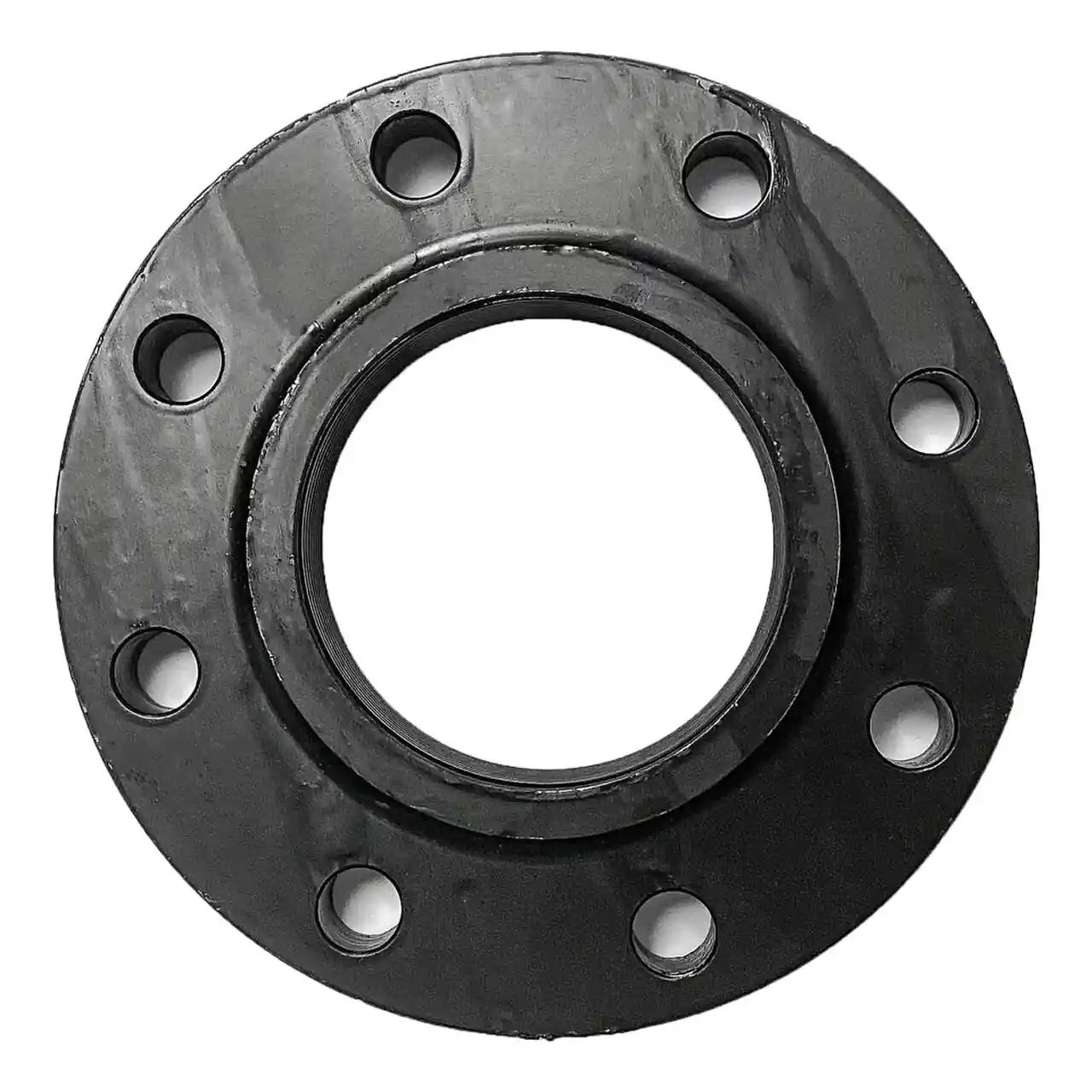
A spectacle blind is a figure 8 shaped steel plate machined to the line size and bolted between two companion flanges as a switchable positive isolation device. One end of the figure is a solid web that blocks the bore completely when it is swung into the line; the other end is a ring with the same full bore as the pipe, which restores flow when it occupies the joint. Rotating the plate 180 degrees about the pipe axis swaps the two ends, and because the unused half always stays attached to the joint, the state of the line is visible to anyone walking past: solid web standing proud of the flanges means blocked, open ring means flowing. The part is dimensioned by ASME B16.48, the steel line blank standard, across Class 150 through Class 2500 in sizes NPS 1/2 through NPS 24 typical, with larger bores handled in the ASME B16.47 context of the companion flanges. Plant vocabulary says figure 8 blind just as often as the standard name; this page uses the standard name and treats the aliases as synonyms.
Procurement engineers specify these blanks at turnaround isolation points, at hot work boundaries, at battery limits between operating units, and at equipment handover interfaces where a valve alone is not accepted as a break. The decision this page settles is narrow and practical: one piece figure 8 blank or a separate paddle blank carried with its ring spacer, which thickness row of the B16.48 table applies at the size and class, which forging matches the line chemistry and temperature, and which gasket, stud, and jack screw package makes the joint switchable in both directions without a grinder and a committee. The answer lands as an RFQ line set, and every chapter below feeds that line set so the isolation is bought as engineered hardware rather than improvised from whatever the stores had on the shelf.
This page treats the spectacle blind as a purchasing object: how the blank thickness and class interact, how the figure 8 and the paddle blank plus ring spacer configurations divide the duty, what the companion flange and gasket package must state, how jack screws make the joint switchable, and how all of it combines into a defensible positive isolation RFQ. It is written for engineers who issue purchase specifications, not for readers who want a brochure summary.
Chapter 1 / 06
What a Spectacle Blind Is and What Is Being Decided
The geometry is the definition. A blind flange ends a pipe: a disk with a bolt circle and no bore, closing the line permanently at the full rating of its class. The spectacle blind lives inside the line instead, sandwiched between two flanges that stay welded to their pipe spools, and it delivers the same geometry tight barrier with the option to remove it by rotation. Because the barrier is a machined steel web rather than a disc seating against a seat ring, there is no wear surface that time can open, no body cavity that can trap pressure, and no operator that can be left half moved. The part is a pressure component in its own right, dimensioned by its own standard rather than borrowed from the flange tables, and it is neither a pipe fitting nor a valve: it is a line blank, bought by size, class, and thickness like the flange it sandwiches into, and the difference matters because a buyer who treats it as a hardware afterthought gets a disk whose thickness matches nothing and whose joint will not close.
What is actually being decided in this purchase is a set of five commitments made in one line set. First, a size and class commitment: NPS and pressure class from the line standard, with the blank thickness taken from the matching B16.48 table, never estimated from a flange table. Second, a configuration commitment: the one piece figure 8 that carries both states on one plate, or the two piece set of a paddle blank and a ring spacer for stations that switch rarely or sit out of reach. Third, a forging commitment: ASTM A105 as the carbon steel default, low temperature and alloy and stainless grades where the line chemistry and temperature demand them. Fourth, a gasket commitment, because the blank seals through two gaskets, one on each face, and both are part of the isolation. Fifth, a switching commitment: jack screws or an approved spreading method, without which the joint cannot be opened and rotated safely under a shutdown clock. A quotation that answers only size and class has quoted a piece of steel, not an isolation.
Against its neighbors the blank occupies deliberate ground, and the full comparison belongs in the selection chapter. A gate valve or a ball valve isolates for operations, but both shut by seat contact and seats wear, and both hold a body cavity full of process fluid between their seats. A double block and bleed valve adds a vented cavity and brings the isolation question much closer, and it is the alternative most plants weigh against blinding, a trade the selection chapter settles properly. A check valve answers only the reverse flow question and is no isolation at all. Where the requirement is a visible, geometry positive break that one person can audit from the walkway, the bolted web is the industry default across refining, chemical, steam, and water service alike, and where the pipe genuinely ends forever, the blind flange is the correct product instead.
Four standards organize the datasheet, with three more in support. ASME B16.48 governs steel line blanks proper: it defines the three product forms, the spectacle blank, the paddle blank, and the paddle spacer, and it tables the blank thickness by class and size from Class 150 through Class 2500. ASME B16.5 and, above NPS 24, ASME B16.47 Series A and B dimension the companion flanges the blank sandwiches into, and their pressure temperature tables set what the joint carries. ASME B16.21 dimensions the gaskets, ASME B46.1 defines the flange surface finish language, and ASME PCC-1 governs how the bolted joint is assembled and re-torqued. NACE MR0175 and ISO 15156 bound the material choice in wet sour service. A datasheet that quotes none of these is a price tag, not a specification.
The RFQ should also state the station, because the blank never arrives alone. Upstream and downstream, operations isolation belongs to a gate valve or a ball valve left locked out while the blank is swung, and the work order that carries the blank usually carries their packing checks too. Instrument taps taken out of service at the same boundary give up their instrument manifold and their diaphragm seal for reuse elsewhere, with impulse lines joined by tube fitting unions that come apart without heat, and a small blank closes the root connection so the tapping survives to the next project. Commissioning adds its own neighbors: the Y strainer elements that caught weld bead all month come out, and the intake basket strainer gets opened and inspected at the same outage. Stating the whole boundary in the RFQ lets one supplier check flange drilling, facing, gasket, and stud compatibility across the station in a single pass instead of four arguments at delivery.
Chapter 2 / 06
How the Blank Holds Pressure and Switches State
Blocked, the solid half of the plate is a flat circular web clamped at its bolt circle and loaded by line pressure across the full bore, the least forgiving geometry in the joint. In words rather than symbols: the bending demand on the web grows with the square of the bore and falls with the square of the thickness, so doubling the diameter at the same class calls for roughly four times the bending capacity, and thickness is the only lever the geometry has. That single relationship explains the B16.48 thickness tables at a glance, and it explains why a blank is never interchangeable between classes: a Class 150 NPS 4 web runs about 12 to 15 mm thick, and the same size climbs steeply through Class 300 and Class 600 as the rating demands, roughly two and a half times the Class 150 thickness at Class 600 as a family pattern. The exact values live in the standard tables, and the order must quote the table, not a remembered number.
The bolt load path is the second half of the mechanics. The stud circle reacts two loads at once: the end load from pressure acting on the bore area, and the residual compression that keeps both gaskets seated against blowout and weep. The end load scales fast with size. An NPS 4 web holding 20 bar carries roughly 16 kN of end load, arithmetic any engineer can check on one line, while an NPS 12 web holding 50 bar carries on the order of 360 kN, at which point the studs, not the web, are the design conversation. That is why assembly practice under ASME PCC-1 belongs in the purchase specification for the blank: cross pattern passes, incremental torque steps, a target bolt stress rather than a bare torque number, and stud length chosen so every nut engages fully with two to three threads showing past the nut face.
Switching is the duty that separates this product from every static pressure part, and it is a procedure, not a gesture. The line is isolated, depressurized, drained, and verified dead. The joint is broken by cracking the nuts in a cross pattern, then the flange faces are spread a few millimeters, no more than the gasket compression plus clearance, using jack screws threaded into tapped holes in one or both companion flanges or an approved flange spreader, never a wedge and a hammer. The plate rotates 180 degrees on the line axis, bringing the open ring or the solid web into the bore as the isolation plan requires. Both gaskets come out and two new ones go in, one on each face, because a gasket that has been compressed and released is a leak budget already spent. The studs then come up in passes to the PCC-1 target.
The visible state is the entire safety argument. When the open ring sits in the bore, the hole through the joint is the full bore and the solid web stands to the side, in plain sight below or beside the pipe; when the web sits in the bore, there is no hole at all and the ring hangs empty. A person on a walkdown with a flashlight can audit the isolation without touching anything, which is precisely what positive isolation means in plant language: the break is a geometric fact, not a seat condition reported by a position switch. Seat based hardware, including the double block and bleed valve treated fully in the selection chapter, always leaves a leak path through body or seat geometry that policy has to manage; the swung web removes the path instead of managing it.
The sealing stack deserves its own arithmetic. The blank carries a gasket on each face, so the joint is flange, gasket, blank, gasket, flange, and both gaskets compress against the flange finish and the machined blank faces. The companion flange finish is the serrated or concentric raised face in the 125 to 250 micron AARH range defined by ASME B46.1, and the blank faces arrive smooth machined, commonly in the 3.2 to 12.5 micron Ra band. At Class 150 utility duty, soft cut gaskets on both faces are standard practice. From Class 300 upward, and anywhere steam or hydrocarbon service sits, a spiral wound gasket with an inner ring on each face is the defensible specification, because the inner ring stops the windings buckling inward under the higher bolt load, and the blank adds a second gasket joint worth of crush to get right.
Pipe strain closes the mechanics chapter because it decides whether the joint can be opened at all two years later. A bolted stack that has been loaded sideways by pipe weight or thermal growth grips its gaskets unevenly and springs when it is broken, and the switching crew pays for that in fights. The station design gives the movement somewhere else to go: an expansion joint elsewhere in the line absorbs the displacement the bolted joint must never be asked to take, and supports hold the spool dead straight on both sides of the blank. Any station that cannot be spread square should be redesigned before the blank is bought, not wrestled with during every outage for thirty years.
Chapter 3 / 06
Types, Construction, and Duty Boundaries
The family sorts by configuration first. The one piece spectacle blind, the figure 8 plate of this page, carries the solid web and the open ring on the same handle, and both states live permanently at the joint: swing one in, the other swings out. It is the configuration for stations that switch more than once a decade and that a person can reach, because switching costs a controlled break of one joint and the hardware is always complete. The tag on the handle carries size, class, material, and heat number, and the handle hole is where the lifting strap and the lockout tag both live, which is why the standard draws it the way it does.
The two piece configuration splits the figure into its halves. A paddle blank, the solid web with its handle, blocks the line; a ring spacer, the open ring with its own handle, restores it. The pair exists for two duties: permanent or long term isolation, where a figure 8's unused half is dead weight and protrusion a plant would rather not have, and installations where the joint cannot be spread far enough to rotate a full figure 8, since a flat paddle slides out of a narrower gap. Site policy governs where the unused half parks: many plants hang it on the studs outboard of the nuts so it cannot walk away, others forbid that on vibration lines and shelf it at the isolation register instead. The purchase decision is the same either way: the blank and its spacer are ordered as one set, tagged as one set, and audited as one set.
Materials sort by temperature and chemistry exactly as the flange forgings do. ASTM A105 carbon steel is the default for ambient through moderate temperature. Below minus 29 deg C the low temperature forgings take over, A350 LF2 as the workhorse with impact test evidence, and the minus 46 deg C territory belongs to LF2 and LF3 forgings on the material curve. For hot service and hydrogen bearing hydrocarbons, the chrome alloys F11 and F22 carry the duty as they do everywhere else in the line class. A182 F304 and F316 cover corrosion and cleanliness duty, and duplex 2205 answers hot chloride chemistry. Wet sour service adds NACE MR0175 and ISO 15156 material limits with hardness requirements, and the certificates that prove them, because a blank is a pressure part and the sour spec does not care that it has no bore.
Boundaries deserve plain statements, because the blank is regularly asked to do jobs that belong to neighbors. It is not a valve: a gate valve or a ball valve gives operations a controllable shutoff on demand, a butterfly valve does the same at large bore and lower cost, and none of the three is a positive break; they complement the blank on the same station rather than competing with it. A check valve is flow logic, not isolation, and belongs on a pump discharge, not at a maintenance boundary. A safety relief valve protects against overpressure and a rupture disk exists to fail at a set pressure: both are relief devices, the exact opposite of a barrier that must hold, and neither has any business on a blinding work order. The blind flange ends a pipe permanently and has its own page in this encyclopedia; the spectacle blank interrupts a pipe reversibly, and the two are ordered on entirely different lines of the specification.
The duty list is where the volume actually lives. Turnaround boundaries between units get swung once per cycle and audited daily while the unit is open. Hot work boundaries inside a live plant get blinds installed before the permit is signed and removed under the same control. Interconnection and battery limit spools, where two operating companies share a line, carry registered blanks because the isolation has contractual weight. Commissioning uses blanks at equipment tie-ins while systems flush and blow, then swings them open for startup. Pump and compressor handover interfaces, temporary jumpovers, and retired tappings round out the list, and every one of them buys the same geometry with a different switching story, which is what the selection chapter sorts.
The duty map below consolidates the pairings into one table a specifier can scan before writing the RFQ.
Duty
Configuration to specify
Check before order
Turnaround unit boundary, switched each cycle
One piece figure 8, jack screws on both companion flanges
Handle clearance to walkway and platforms for rotation
Hot work boundary inside a live plant
Figure 8 or paddle blank set, registered and tagged
Permit sequence and lockout tagout before the break
Permanent or multi year isolation
Paddle blank installed, ring spacer parked per site policy
Isolation register entry and periodic walkdown audit
Joint with limited spread distance
Paddle blank and ring spacer set, slides without full rotation
Spread allowance versus handle and web geometry
Battery limit between two operators
Figure 8 with dual tagging, both owners named
Class, facing, and forging matched to both sides of the fence
Commissioning tie-in, flushed then opened
Figure 8 with sacrificial gaskets replaced at startup
New gaskets both faces at the switch to running duty
Sour service boundary
NACE MR0175 material limits with hardness certificates
EN 10204 3.1 certificate and heat number on the handle tag
Chapter 4 / 06
Key Specification Parameters
The table below decodes the datasheet lines that decide whether a quoted blank matches the isolation duty. Each row is purchase defining; the paragraphs after the table explain what to demand and what a weak answer looks like.
Attribute
Typical range or options
What it decides
Nominal size
NPS 1/2 to NPS 24 per B16.48; larger per B16.47 context
Web diameter, thickness row, and bolt pattern of the joint
Pressure class
Class 150 to Class 2500 in B16.48 steps
Thickness table row, stud load, and gasket construction
Thickness, representative
About 12 to 15 mm at NPS 4 Class 150; steeply thicker by class
Pressure capacity of the web; the table governs, not memory
Configuration
Spectacle blank one piece; paddle blank plus ring spacer set
Switching method, spread distance, and handle access
Bore of spacer half
Full bore to match pipe schedule, stated on order
Whether the open state restores true line bore
Forging
A105, LF2, LF3, F11, F22, F304, F316, duplex 2205
Temperature window, chemistry resistance, sour acceptance
Gaskets, both faces
Soft cut at Class 150; spiral wound gasket with inner ring Class 300 up
Seal integrity through two joints stacked in one bolted stack
Jack screws
Tapped holes in companion flanges, screws and covers quoted
Whether the joint can be spread square and resealed in outage time
Companion flange type
Weld neck usual; facing RF standard, RTJ by line class
Joint geometry, gasket seating, and stud length
Certificates
EN 10204 3.1 with heat number and hardness where sour applies
Traceability from the handle tag back to the melt
The thickness row deserves its own paragraph because it is where unofficial products show themselves. A blank cut from plate to an approximate thickness carries no class at all, and a buyer who accepts it has bought unidentified steel with a handle. Demand the B16.48 table reference by class and check the quoted web thickness against it; the figures in the table below are family markers for orientation, honest ranges rather than substitutes for the standard, and the sources at the end of this page carry the published dimension sheets. The pattern to internalize is the steepness: thickness grows far faster than class factor across the table because the flat web has no hub helping it, which is also why upgrading a blank one class is never a small edit.
Size
Class 150 web
Class 300 web
Class 600 web
NPS 2
about 8 to 10 mm
about 10 to 12 mm
about 14 to 16 mm
NPS 4
about 12 to 15 mm
about 15 to 18 mm
about 22 to 28 mm
NPS 8
about 17 to 20 mm
about 22 to 26 mm
about 32 to 38 mm
NPS 12
about 22 to 25 mm
about 28 to 32 mm
about 42 to 48 mm
Jack screws are a purchase line, not a site improvisation. The screws thread into tapped holes in one or both companion flanges and bear on the opposite face to spread the joint square, typically a few millimeters of travel, and the RFQ should name the quantity, size, and thread, the hard point or pusher plates that protect the opposing flange face, and the covers or plugs that keep the tapped holes clean between outages. Where the existing flanges carry no tapped holes, hydraulic flange spreaders designed for the duty are the approved alternative, and either way the switching method belongs in the specification because it sizes the outage labor. A joint that can only be opened with wedges and hammers is an injury report that has not happened yet.
Beyond the tables, the datasheet must state the evidence. The spacer half bore matched to the actual pipe schedule, so the open state restores the true line bore and not a guess. The face finish of the blank itself, smooth machined, commonly 3.2 to 12.5 micron Ra, because both gaskets seat against it. The handle tag content: size, class, material grade, heat number, and the standard, stamped for life. The material certificate EN 10204 3.1 tying chemistry and heat treatment to that heat number, with hardness values stated where NACE MR0175 applies. And the confirmation that both companion flanges, usually weld neck, are quoted with matching facing and drilling, because a blank that does not drop between its flanges without reaming is a delay dressed as a delivery. The drilling itself follows the flange standard, since the blank shares the bolt circle of its flange pair rather than any pipe fitting dimension logic, and a mismatched hole pattern is caught at the table, not on the rack.
Chapter 5 / 06
Selection Decision Factors and RFQ Language
The decision sequence is short enough to run as a checklist in a specification meeting, and each step eliminates a class of quotations before price comparison starts.
Confirm the isolation policy honestly: how often the station switches, who audits it, and whether the plant accepts seat based isolation with lockout or demands a visible geometric break.
Fix NPS and class from the line standard, then take the web thickness from the matching B16.48 table and quote the table by name.
Choose the configuration: one piece figure 8 for reachable, more than once a decade stations; paddle blank plus ring spacer for long term isolation or tight spread geometry.
Choose the forging from temperature and chemistry: A105 default, LF2 and LF3 below minus 29 deg C, F11 and F22 for hot and hydrogen service, F304, F316, and duplex 2205 for corrosion, all under NACE MR0175 where sour applies.
Choose the gaskets with the class: soft cut both faces at Class 150 utility, spiral wound gasket with inner ring on each face from Class 300 up and for steam and hydrocarbons.
Specify the switching package: jack screw quantity, size, and thread, pusher protection, hole covers, or an approved spreader, plus new gaskets and stud hardware every switch.
Fix the verification: dimension check against the named table, handle tag content, EN 10204 3.1 certificate, hardness where sour applies.
State the station: upstream and downstream operational valves, instrument tappings retired or kept, and the register entry that will carry this isolation for the plant life.
The isolation policy question deserves the full comparison, because it is the decision this page actually settles for most buyers. A double block and bleed valve closes two seats and vents the cavity between them, and in good condition with the vent proven open it is accepted as isolation in many plant policies; but it remains a seat based device, its leak path is managed rather than removed, its cavity can trap and corrode, and its proof depends on maintenance and testing discipline over years. The swung blank removes the question: with the web in the bore there is no geometry through which the line can pass fluid, and the proof is eyesight. The trade runs the other way too: the valve switches in seconds from the control room and costs no outage labor, while the blank costs a joint break with new gaskets and torque passes every switch. Plants that isolate rarely and audit hard buy blanks at the boundaries and valves for operations, and the honest specification states which duty each station serves instead of pretending one product covers both.
Against the valve neighbors the same honesty applies, briefly. A gate valve or a ball valve with a lock and chain is operational isolation, fine for daily duty and never a positive break. A butterfly valve economizes at large bore and holds the same seat honesty. A check valve on a pump discharge stops reverse rotation and water hammer, it does not isolate anybody. The blind flange ends a line permanently; where a line might someday return to service, a blank in a spool beats a welded cap and a cutting crew. And the relief devices stay on their own side of the logic: the safety relief valve that protects the system and the rupture disk that sacrifices itself on demand are reasons the blank must hold, never substitutes for it.
The consumables line thinks the same way as the hardware line. Two gaskets per switch, ordered in multiples the outage schedule can consume, because a switch without new gaskets is a leak on a plan. One stud and nut set held spare per station for the bolt that galls on the third outage. The Y strainer element that protects the seat of the upstream control hardware during commissioning, the spare basket for the intake basket strainer, and the gaskets for those bodies too, all ordered against the same shutdown date, because station spares are specified in advance, not discovered at two in the morning.
The application map below turns the rules into a table the project file can carry.
Application
Construction to specify
Check before order
Unit boundary at each turnaround
Figure 8, A105 or F22 per line class, jack screws both flanges
Rotation clearance and handle tag against the register
Steam header isolation, Class 600
F11 or F22 web, spiral wound gasket with inner ring each face
Thickness from the B16.48 Class 600 row, not scaled from Class 150
Long term retired line
Paddle blank installed, ring spacer parked per policy
Isolation register entry and annual walkdown
Sour gas battery limit
NACE MR0175 forging with hardness certificates
Both operators sign the dual tag before any switch
Commissioning tie-in
Figure 8 with sacrificial soft gaskets
New gaskets at the switch to running duty
Pump handover spool
Blank plus upstream gate valve locked out
Check valve stays on discharge for reverse rotation duty
The RFQ block should be written once and reused. A complete block reads: quantity of sets; NPS; class; configuration, one piece figure 8 or paddle blank plus ring spacer; web thickness per the named B16.48 table; spacer bore matched to pipe schedule; forging grade with the EN 10204 3.1 certificate and hardness where sour applies; facing of the companion flanges, usually weld neck raised face; gasket construction both faces; jack screw quantity, size, thread, and covers, or the declared spreader method; stud and nut package; handle tag content including heat number; and the delivery evidence, dimension sheet and material certificate with the hardware. A quotation returned without the table reference or the certificate is incomplete at any price.
Chapter 6 / 06
Installation, Standards, Failure Modes, and Maintenance
Installation quality decides whether the station can be switched for the next thirty years. Verify zero energy first: isolated, depressurized, drained, and proven by the permit system, because the person cracking the nuts is the person the whole ceremony protects. Break the joint in a cross pattern, spread it square with the jack screws, a few millimeters only, and rotate the plate without levering it against the flange faces, which scratch and score precisely where the gasket must seal. Seat two new gaskets, one each face, confirm the spacer bore or the solid web is centered in the joint, and bring the studs up in incremental cross pattern passes to the PCC-1 target with the named lubricant. On hot service, re-torque after the first thermal cycle, because gasket creep and bolt relaxation both show up there, and the hot torque pass is the cheapest insurance the joint will ever get. Keep the spool square and supported on both sides of the joint throughout, because the bolted stack absorbs none of the pipe movement that the expansion joint elsewhere in the line was installed to take.
Storage and handling decide whether the blank survives between uses. A plate stored misaligned, thrown against steel, or used as a walkway plate arrives with scored and burred faces that engrave the flange face on the next assembly and start a leak that gets blamed on the gasket. Store blanks on edge on racks, dry, with their gaskets and their tag intact, and retire any plate whose faces show dents across the sealing band. The isolation register carries each station, the state of each blank, the date of each switch, and the permit that authorized it; the lockout tagout system locks the upstream operational valve, and the status board plus the visible web make the state audit proof from the ground. A blank whose state is known only to the last crew that touched it is not isolation, it is a rumor.
The standards set the verification frame. ASME B16.48 defines the three product forms and tables the thickness by class and size. ASME B16.5 and B16.47 Series A and B dimension the companion flanges and their pressure temperature ratings. ASME B16.21 dimensions the gaskets, ASME B46.1 defines the finish language the seating discussion needs, and ASME PCC-1 governs assembly and re-torque. NACE MR0175 and ISO 15156 bound the materials in wet sour service, and EN 10204 3.1 carries the evidence. A specification that cites the standards by name in the RFQ block transfers the burden of proof to the supplier, which is where it belongs.
Failure modes in service follow a short and predictable list. Wrong state at the wrong time is the first and worst: a line opened or blocked in error because the register, the tag, and the plate disagreed, which is why the status board audit belongs to the daily walkdown and every switch closes a permit. Gasket blowout or weep from under-torque or from gaskets reused once too often, the classic economy that costs an outage. Corrosion at the pipe to flange zone under insulation, where CUI attacks the weld neck to pipe welds and the flange faces alike, and the blank's second joint doubles the surface that must be inspected when the insulation comes off. Scored flange faces from careless rotation or from a stored plate dragged across them, a leak path no bolt load closes. Stud relaxation and gasket creep at temperature, which is a re-torque event, not a failure. And trapped pressure between a closed operational valve and a freshly swung web when the sun or steam heats the spool: the fluid has nowhere to go, which is why the safety relief valve protecting that segment belongs in the isolation study and why the rupture disk on the adjacent header stays on the relief side of the logic where it was designed to live.
Maintenance is mostly inspection discipline, and the intervals ride the shutdown calendar. At each outage the station gets its gaskets renewed at the switch, the flange faces wiped and inspected for scoring and corrosion pits across the sealing band, the jack screw threads chased and covered, and the tag reconciled against the register. The walkdown between outages checks one thing, the visible state, and it checks it daily where the isolation carries weight. Instrument tappings retired at the same boundary give up their instrument manifold and their diaphragm seal for the store, the tube fitting unions come off with the impulse lines so nothing corrosion prone hangs on the pipe, and the small blank on the root connection joins the same register as its larger neighbor. None of this costs a tenth of one isolation error, and every inspection produces evidence the next RFQ can use, which is how a purchasing file gets smarter instead of just older.
FAQ
What is the difference between a spectacle blind and a blind flange?
A blind flange is a permanent end closure: a bored-less disk that terminates a pipe, vessel nozzle, or valve port at full class rating. A spectacle blind sits inside a continuing line, sandwiched between two companion flanges, and blocks or opens the bore reversibly by rotating its figure 8 plate 180 degrees. The flange ends the line; the blank interrupts it. Where a line may return to service, order the blank, and where the pipe genuinely stops forever, order the flange.
When should I order a paddle blank and ring spacer set instead of a one piece figure 8?
Order the two piece set for permanent or multi year isolation, where the unused half of a figure 8 is dead weight and a protrusion, and for joints whose flanges cannot be spread far enough to rotate a full figure 8 plate, since a flat paddle slides out of a narrower gap. Order the one piece figure 8 for stations that switch more than once a decade and can be reached, because both states then always travel with the joint and nothing can go missing.
Can a double block and bleed valve replace a spectacle blind?
It depends on the plant isolation policy, and that is the honest answer. A double block and bleed valve with its cavity vent proven open is accepted as isolation in many policies and switches in seconds without outage labor. But it stays a seat based device whose leak path is managed, not removed, and its proof depends on testing discipline over years. The swung blank gives a geometric break auditable by eyesight. Many plants use both: valves for operations, blanks at hard audit boundaries.
How do I know the web thickness I am ordering is correct?
Take the thickness from the ASME B16.48 table row for your size and class and quote that table by name in the RFQ, then check the quoted value against the published dimension sheets in the sources below. As family markers, a Class 150 NPS 4 web runs about 12 to 15 mm and the same size climbs steeply through Class 300 and Class 600. A blank cut from plate to an approximate thickness carries no class at all; demand the EN 10204 3.1 certificate with the heat number.
Do I need jack screws to install and switch a spectacle blind?
Yes in practice, because the joint must be spread square by a few millimeters, no more, to rotate the plate, and jacking screws threaded into tapped holes in the companion flanges do that in a controlled way. The alternative is an approved hydraulic flange spreader; wedges and hammers are not an approved method and damage the flange faces the gaskets seal against. Quote the jack screw quantity, size, thread, pusher protection, and hole covers with the blank.
Which gaskets go on each side of the blank?
Two gaskets, one on each face of the plate, every assembly, always new. At Class 150 utility duty, soft cut gaskets both faces are standard. From Class 300 upward, and for steam and hydrocarbon service at any class, specify a spiral wound gasket with an inner ring on each face: the higher bolt load of two stacked joints crushes unwound gaskets, and the inner ring stops the windings buckling inward. Reusing gaskets across a switch is the cheapest leak on the plant.
How is the state of the blind verified during operation?
By eyesight, which is the point of the product. When the solid web sits in the bore it stands visible and the open ring hangs beside it; when the ring sits in the bore the open hole shows and the web swings clear. The daily walkdown reads the plate, the handle tag, and the isolation register together, and the lockout tagout on the upstream operational valve backs the reading. A register entry that disagrees with the plate is a stop work finding, not a paperwork note.