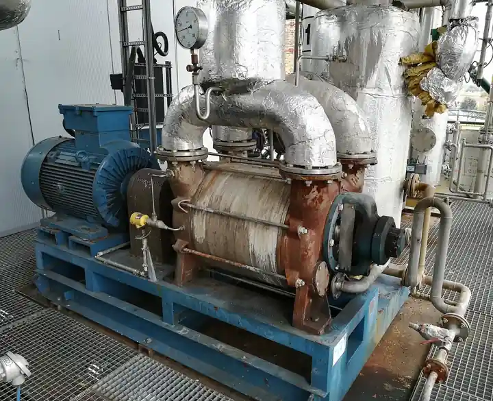
A rotary vane pump is a positive displacement machine whose rotor sits eccentric to the pump chamber, with sliding vanes that extend outward against the chamber wall as the rotor turns. The vanes divide the crescent-shaped space between rotor and wall into cells whose volume grows on the suction side and shrinks on the discharge side, moving a fixed volume of gas or liquid per revolution. The design appears in two industrial families that share the kinematics but little else: the oil-sealed rotary vane vacuum pump, the default rough and medium vacuum workhorse from laboratory bench to packaging line, and the sliding vane transfer pump for moving clean, low viscosity liquids such as fuel oil, solvents, and LPG against moderate pressure.
Specifying a rotary vane pump means separating those two families first, because the selection parameters barely overlap. The vacuum buyer is buying ultimate pressure, pumping speed, and vapor tolerance through gas ballast; the transfer buyer is buying differential pressure, viscosity window, and suction lift. This page works both branches with the numbers a specifier needs: stage count and the pressure floors it buys, gas ballast behavior on condensable vapors, oil selection and its failure modes, displacement and volumetric efficiency for liquid duty, and the RFQ lines that make quotes comparable.
This page treats the rotary vane pump as two specified machines in one kinematics: the oil-sealed vacuum pump judged by ultimate pressure, pumping speed, and gas ballast vapor tolerance, and the sliding vane transfer pump judged by differential pressure, viscosity window, and suction lift, each with its materials, standards, failure modes, and RFQ lines.
Chapter 1 / 06
What a Rotary Vane Pump Is and What Is Being Decided
The mechanism is one idea executed with discipline. A cylindrical rotor runs on a shaft offset from the chamber centerline. Slots in the rotor carry vanes that are free to slide radially; centrifugal force, and in sealed designs the oil film, presses each vane tip against the chamber wall. As the rotor turns, the space between two adjacent vanes on the wide side of the crescent grows, drawing fluid in through the inlet port; carried over the top, the same space shrinks on the narrow side and expels fluid through the discharge port. There is no valve train in the pump itself: the port geometry times the cells, which is why vane machines run quietly, pulse mildly, and tolerate high speed, typically 1450 to 3000 rpm on pole-assigned motors.
The decision the buyer is actually making depends on the branch. In vacuum service the pump is a air and vapor mover whose product is pressure reduction: the questions are how low an ultimate pressure the process needs, how much pumping speed at working pressure, and how much condensable vapor the pump must swallow without oil degradation. In liquid transfer the pump is a metering-adjacent conveyor: the questions are differential pressure, liquid viscosity and lubricity, flow rate, and whether the liquid can be allowed to contact the sliding mechanism at all. A buyer who quotes a vacuum pump for fuel transfer, or a dry vane blower where an oil-sealed stage is required, has solved the wrong problem elegantly.
Positioning against neighbors matters because overlap is partial. On the vacuum side, the oil-sealed vane machine owns the rough to medium vacuum band, roughly atmospheric down to one-hundredth of a millibar ultimate on two-stage units, and it is the standard backing pump for roots and turbomolecular stages above it. A generic vacuum pump leaf in this encyclopedia covers the family landscape; the vane machine is the segment with oil, gas ballast, and the deepest catalog. On the liquid side, the vane pump sits between a gear pump, which handles higher viscosity and higher pressure with similar quietness, and a centrifugal pump, which wins on flow and simplicity but loses self-priming and low-flow-differential capability. For heavier, abrasive, or shear-sensitive liquids the honest comparisons are a progressive cavity pump or a peristaltic pump; for chemically aggressive fluids, a magnetic drive pump removes the shaft seal question entirely.
What is being decided, stated as an engineer would put it in a spec review: pick the branch, then size the machine to the duty point with margin for the worst vapor or viscosity case, then pick materials and seals for the chemistry, then pick the accessory set, inlet protection, exhaust oil separation, and anti-suckback, that keeps the machine alive between services. The rest of this page follows exactly that sequence.
Chapter 2 / 06
Vane Kinematics and Vacuum Physics
Displacement is geometry times speed. The theoretical swept volume per revolution follows from chamber bore, rotor diameter, eccentricity, and axial length; practical catalog frames run from fractional units of a cubic meter per hour, bench pumps near 1 to 5 cubic meters per hour, through mid-range machines of 20 to 100 cubic meters per hour, to large single-stage units of several hundred cubic meters per hour for rough vacuum duty. Pumping speed at atmospheric and near-ultimate pressure differs from displacement because internal leakage, oil sealing behavior, and gas compression heat all take their share; the honest datasheet plots speed versus pressure, and the honest buyer reads the value at the process working pressure, not the headline displacement figure.
In vacuum service the oil is not a lubricant afterthought; it is a sealing and performance element. Oil fills the clearances between vane tips, rotor ends, and chamber faces, cutting internal backflow by orders of magnitude and setting the pressure floor. Single-stage oil-sealed vane pumps reach ultimate pressures around one-hundredth of a millibar, with partial pressure of air lower still when the gas ballast is shut. Two-stage designs, a high vacuum stage discharging into a roughing stage, push ultimate to a few ten-thousandths of a millibar because the second stage runs against a much lower fore-pressure. Those two numbers, plus pumping speed at working pressure, define whether the vane pump alone is enough or whether it becomes the backing stage of a roots blower combination, where the pairing multiplies speed in the millibar band and improves effective ultimate.
Gas ballast is the mechanism that lets an oil-sealed pump process condensable vapors, and it deserves its arithmetic. Vapor entering a pump chamber compresses along its saturation curve; without intervention, water vapor for example would condense inside the pump when its partial pressure passes saturation at compression temperature, emulsifying the oil and destroying ultimate pressure. The gas ballast admits a metered quantity of air into the compression phase, raising the total pressure at which discharge opens so that the vapor partial pressure never reaches saturation before the exhaust valve lifts. The cost is a higher ultimate pressure with ballast open, typically about one millibar class instead of the ten-thousandths, and a water vapor tolerance rating, commonly between 10 and 40 millibar of water vapor partial pressure depending on pump size and temperature, which is the number the process vapor load must be checked against. Warm pumps tolerate more vapor; that is why continuous vapor duty specifies a pump run up on ballast before process vapor arrives.
In liquid transfer service the same kinematics behave differently because the liquid itself is the sealing medium. Volumetric efficiency, the ratio of delivered flow to swept displacement, runs typically 85 to 95 percent on thin lubricating liquids and falls as viscosity rises or clearance wear grows. Differential pressure is bounded by the sealing ability of the vane-to-wall film: catalog vane transfer pumps work to about 7 to 10 bar continuously, with heavier-duty variants to about 15 bar, and above that the mechanism leaks back or the vanes overload, territory that belongs to gear or piston machines. Suction lift of 5 to 7 meters on thin liquids is standard because the pump self-primes; the number degrades with viscosity, and the specification should demand a priming curve, not a single figure, when the application pulls from a sump below the pump.
Power draw follows the branch too. A vacuum pump pulls near-unloaded power at atmospheric inlet falling as pressure drops, then a floor set by oil churning and compression of ballast air; the motor is sized to the worst case, usually steady operation at working pressure with ballast open on vapor duty. A transfer pump on thin liquid draws power almost linearly with differential pressure and speed, and on viscous liquid the churning loss grows with viscosity, which is why heated or winterized installs specify motor service factors and jacketed bodies for heavy fuel oil grades. Both branches share one rule: the machine must never be dead-headed for long, because a closed discharge on a positive displacement pump turns shaft power into heat with nowhere to go, and an internal relief valve or a bypass loop back to source is the standard protection.
Chapter 3 / 06
Types, Materials, and Duty Boundaries
Vacuum branch first. Single-stage oil-sealed pumps are the general duty machines: packaging, degassing, degas of transformer oil, vacuum forming of thermoplastics, backing for large roots sets where a floor near one-hundredth of a millibar suffices. Two-stage pumps buy the deeper ultimate and cleaner partial pressures for laboratory work, semiconductor load-lock roughing, freeze drying, and distillation. Within each stage class, variants add a gas ballast valve sized for the vapor load, an anti-suckback valve that closes on stop so oil is not drawn into the vacuum volume, and exhaust mist eliminators with oil return that keep pump oil inventory and plant air both clean. Versions with solvent-resistant oils, fluorinated oils for oxygen service where hydrocarbon oil is an ignition hazard, and corrosion-protected internals for acid vapors round out the catalog; on aggressive chemistry the realistic competitor is a dry pump, and the trade is oil cost against dry-machine capital.
Liquid branch second. Sliding vane transfer pumps divide into light-duty fuel and oil transfer units, mid-range industrial machines for solvents and LPG, and heavy-duty versions with through-shaft vane lubrication for continuous process duty. Materials follow the liquid: cast iron bodies and vanes with steel rotors for fuels and oils, ductile iron with bronze or carbon vanes where the liquid has marginal lubricity, and stainless builds for solvents and corrosives at a price step. Mechanical shaft seals, packed glands, and on LPG double seals with a barrier, are selected by hazard class. The internal relief valve is standard on process machines; on flammable service the relief returns to the pump inlet or source tank, never to atmosphere.
The duty boundaries are sharp when stated honestly. The vane transfer pump stops being right above about 15 bar differential, where a gear pump takes over; above roughly 500 centistokes working viscosity the vane chamber stops filling cleanly and a progressive cavity pump or a heated gear machine is correct; on abrasive or solids-laden liquid the vane edges wear fast and a peristaltic pump or a slurry-capable design wins; where the duty is actually volumetric dosing rather than transfer, a metering pump with its own calibrated repeatability is the honest instrument; and in sanitary product handling a lobe pump with its cleanability certificates owns the duty where a vane machine would need daily strip-down; on shear-sensitive polymers a low-shear machine is specified, and on any toxic or flammable liquid with zero tolerance for seal leakage the magnetic drive pump removes the rotating seal entirely. On the vacuum branch, the oil-sealed vane pump stops being right when the process cannot tolerate oil backstreaming, in which case a diaphragm pump covers small laboratory flows or a dry screw or claw machine covers process flows; when vapor loads run far beyond ballast tolerance, a liquid ring machine trades depth of vacuum for unlimited condensable tolerance.
Variant
Working band
Best duty
Hard boundary
Single-stage oil-sealed
atmosphere to approx. 0.01 mbar ultimate
Packaging, forming, backing roots sets
Oil backstreaming unacceptable to process
Two-stage oil-sealed
to a few 0.0001 mbar ultimate
Lab, freeze drying, load locks, distillation
Same oil limit; cost and speed at rough end
Sliding vane transfer
to 7 to 10 bar differential, some 15 bar
Fuel oil, solvent, LPG transfer
Above approx. 500 cSt viscosity
Dry vane compressor
pressure and rough vacuum, oil-free
Oil-free air, aeration
No deep ultimate; vane wear without oil film
One boundary note that saves money: many duties quoted for two-stage pumps need only a single stage with the right oil and ballast regime, and many duties quoted for large vane transfer pumps are better served by a centrifugal pump with a good suction arrangement once priming is engineered. The vane machine earns its premium where self-priming, positive displacement behavior at low flow, or the specific vacuum band is genuinely required, and the RFQ should be able to say which of the three it is buying.
Chapter 4 / 06
Key Specification Parameters
The decode table separates the vacuum and transfer parameter sets because they answer different questions, and because vendors quote the flattering half when the RFQ does not force the rest. Every row is a line to carry with a number.
Parameter
Typical catalog spread
What it decides
Ultimate pressure, total
0.01 mbar single-stage to 0.0001 mbar class two-stage
Whether the pump alone reaches process pressure or backs another stage
Pumping speed at working pressure
1 to 500 m3/h by frame
Pumpdown time and process gas throughput
Water vapor tolerance, ballast open
10 to 40 mbar water vapor partial pressure
Continuous vapor duty without oil emulsification
Oil charge and oil class
0.3 to 20 L; mineral, synthetic, fluorinated
Service interval, chemistry compatibility, oxygen service legality
Transfer differential pressure
7 to 10 bar standard, 15 bar heavy duty
Whether the mechanism seals the duty point
Viscosity window, transfer
1 to 500 cSt working, heated builds above
Cell filling, vane loading, priming behavior
Suction lift
5 to 7 m on thin liquids, less with viscosity
Sumption-to-pump geometry freedom
Seal and relief arrangement
Mechanical, packed, double with barrier; internal relief to inlet
Hazard containment and dead-head protection
Motor and noise
0.25 to 30 kW; 60 to 85 dB(A) class
Energy and workplace noise compliance
Ultimate pressure needs reading care. The total ultimate includes hydrocarbon partial pressure from the oil; the air partial pressure, what a cold trap or gas analyzer would see, is lower. For processes that only need pumping, quote total; for processes sensitive to contamination, demand the air partial pressure figure and the oil class together, and consider a trap or a dry machine. Pumping speed at working pressure should be taken from the speed-pressure curve at the actual process pressure: headline displacement, the value at atmospheric inlet, overstates mid-band speed by a third or more on some frames.
Vapor tolerance is the number that decides service cost on wet processes. Write the process vapor load as a partial pressure at the pump inlet and compare against the tolerance rating with ballast open; keep 30 percent margin because tolerance falls with inlet pressure and cold oil. Where the vapor is solvent rather than water, check the oil compatibility class and expect shorter oil life; where the vapor is corrosive, the corrosion-protected variant with synthetic oil is not optional, it is the warranty condition.
On the transfer side, differential pressure and viscosity together size the machine, and their pair behavior is what cheap datasheets hide. A pump rated 10 bar on thin oil may be a 4 bar pump on 200 centistoke fuel at winter temperature. Ask for the flow-pressure-viscosity family or at least three points across the expected envelope, and specify the motor for the worst corner, not the rated point. For LPG and volatile liquids, add net positive suction head margin in the liquid class and a double seal with barrier fluid and its own monitoring, because vapor lock at the vane chamber presents as cavitation noise and rapid vane wear long before it presents on a data sheet.
Accessory parameters carry reliability budgets. Inlet protection, a screen or a Y strainer upstream sized one class below the pump inlet, keeps vane chips from becoming rebuild causes; on vacuum service the inlet filter also keeps particulate out of the oil. Exhaust mist elimination with oil return preserves oil inventory on continuous duty and is mandated by workplace emission limits in many jurisdictions. The anti-suckback valve is cheap insurance that power loss does not fill the vacuum volume with oil. None of these are performance figures, and all of them belong in the RFQ by name.
Chapter 5 / 06
Selection Decision Factors and RFQ Language
The decision sequence is branch-first because every later step inherits the branch choice.
Fix the branch: vacuum duty or liquid transfer. State the goal as a number: working pressure and throughput, or flow at differential pressure and viscosity.
Vacuum branch: compute pumpdown or throughput need against the speed-pressure curve at working pressure, then check ultimate pressure class, then vapor load against ballast tolerance with margin, then oil class against chemistry and oxygen rules.
Transfer branch: state liquid, working viscosity range including seasonal and temperature extremes, differential pressure, and required flow; then confirm the mechanism envelope, pressure, viscosity, lubricity, and only then compare against gear or screw alternatives honestly.
Select materials and seals by chemistry and hazard class: cast iron for fuels, stainless for solvents and corrosives, double barrier seals for hazardous fluids, corrosion-protected internals for acid vapor duty.
Select the accessory set: inlet strainer, exhaust mist eliminator with oil return, anti-suckback valve, internal relief and bypass for transfer, ballast valve sizing for vapor duty.
Size the motor for the worst corner of the envelope, include service factor, and specify noise class where the install is occupied.
Write the RFQ with every line item from Chapter 4 and require the speed-pressure curve or the flow-viscosity family with the quote.
Cost behavior is frame-size and branch driven. As a planning spread: small single-stage vacuum frames of a few cubic meters per hour sit at the bottom of the range; two-stage laboratory frames of similar displacement run 1.5 to 2 times that; process frames of 60 to 250 cubic meters per hour price by frame with oil system and accessories adding 20 to 40 percent; transfer machines price by pressure class and metallurgy, with stainless and double-seal builds commonly 2 to 3 times the cast iron base on the same duty. Fluorinated oil charges and corrosion-protected variants add material-driven increments. The comparison table positions the realistic alternatives.
Option pair
Relative cost
What you gain
What you pay in
Single-stage vs two-stage oil-sealed
1.0 vs 1.5 to 2.0
Deeper ultimate, cleaner partial pressure
Speed at rough end, price, sensitivity to dirt
Oil-sealed vane vs dry screw or claw
1.0 vs 2 to 4
Oil-free process side
Capital, usually shallower ultimate alone
Vane vs liquid ring on wet vapor duty
1.0 vs 1.2 to 1.8
Unlimited condensable tolerance
Water management, poorer ultimate
Vane transfer vs gear pump
1.0 vs 1.1 to 1.5
Higher pressure, higher viscosity reach
Cost, noise on thin liquids
Vane transfer vs magnetic drive pump
1.0 vs 1.5 to 2.5
No rotating seal on hazardous liquid
Dry-run sensitivity, solids intolerance
The RFQ checklist writes out as: branch and duty numbers; working pressure and throughput, or flow, differential, and viscosity range; ultimate pressure class and air partial pressure where process purity matters; vapor identity, load as partial pressure, and required tolerance margin; liquid chemistry and material demands; seal arrangement and hazard class; accessory list by name, inlet strainer or Y strainer, mist eliminator with oil return, anti-suckback, internal relief; motor sizing basis and service factor; oil class and charge with service interval; performance curves required with quote; and the applicable measurement standard, with vacuum performance to ISO 21360 as the reference basis for comparing quoted speed and ultimate figures on equal terms.
Surrounding pipework belongs in the same review. A ball valve at the pump inlet for isolation and a check valve or ball valve at discharge are the minimum; every isolation valve needs a means of preventing dead-head, either an internal relief or a bypass loop, on positive displacement service. Downstream, a Y strainer protects the check valve and the process from vane debris during break-in. These are commodity lines, but they are also where most first-year field failures are traced, so the RFQ that includes them gets a machine that starts and survives commissioning.
Chapter 6 / 06
Installation, Standards, Failure Modes, and Maintenance
Installation discipline for vane machines is mostly about what must not reach the mechanism and what must leave it. Vacuum installs: mount the pump where oil can be changed without spill theater, keep the exhaust mist eliminator vented to a safe place, fit the inlet screen, and on process duty run the pump warm on closed ballast before admitting vapor so the ballast tolerance is at its rated value. Keep inlet piping short and one size up; conductance losses at rough vacuum eat speed faster than buyers expect, and a long narrow inlet line can cost more speed than the difference between two pump frames. Liquid installs: mount close to source with a straight suction run, a full-bore ball valve for isolation, and a strainer; on volatile liquids calculate suction head at the worst liquid temperature and add margin, because vapor locking at the vanes is the failure mode nobody budgets.
Standards worth naming in the RFQ: vacuum performance characterization follows ISO 21360, which is the basis for comparing quoted pumping speed and ultimate pressure between vendors; explosion-rated variants carry ATEX or IECEx equipment marking by zone and category; LPG and fuel transfer builds follow the relevant pressure equipment and hazard-class rules for seals and relief. Motor frames, noise emission values, and workplace exposure limits round out the compliance paragraph. There is no single product standard that replaces the duty analysis in Chapters 4 and 5, and a vendor who claims otherwise is selling a catalog, not a machine.
Failure modes arrive in a known order. First, oil degradation on vapor duty: emulsified or oxidized oil shows as falling ultimate pressure, rising motor current, and discolored oil sight glass; prevention is ballast discipline, oil class matched to chemistry, and interval changes set by oil condition, not calendar. Second, vane and chamber wear from ingest: chips and grit score the chamber wall, vane tips lose contact, and both vacuum depth and transfer efficiency fall together; prevention is the inlet screen or strainer, which is a wearing part to service, not a decoration. Third, stuck vanes from varnish, oxidized oil gluing vanes in their slots, presenting as flow or speed loss at fixed rpm; an oil flush and the correct synthetic class cures early cases, rebuild cures late ones. Fourth, shaft seal leaks, which on hazard-class liquids are a reporting event, arguing for barrier seals or magnetic drive alternatives at selection time. Fifth, anti-suckback failures that fill vacuum volumes with oil after power dips, annoying in a laboratory and expensive in a process chamber; the valve is cheap, test it at commissioning and after every oil change.
Maintenance is oil-centered on the vacuum branch. Sight-glass checks weekly, oil change at the condition interval, typically a few hundred to a couple thousand hours depending on vapor load, with the first change early in life to clear break-in wear. Vane inspection at rebuild: vane length versus minimum, chamber bore versus maximum, both against the vendor wear table, because those two numbers decide whether a kit refresh is enough or the chamber is finished. On transfer machines, the same discipline applies to the liquid itself as the sealing medium: clean liquid and correct viscosity are the maintenance program, and the strainer is where the evidence collects. Keep a running record of current draw at a reference condition; a slow rise is the cheapest early warning of wear or oil trouble that a schedule will only confirm later.
One scoping note for system designers: a vane pump rarely works alone on either branch. Vacuum systems chain it to a roots booster for speed in the millibar band or use it as forepump to a turbomolecular stage; transfer systems pair it with valves and relief hardware that make the loop safe. The pump selection is correct when the chain around it was specified with the same attention, and the RFQ language in Chapter 5 is written to be copied into exactly that larger specification.
FAQ
What ultimate pressure can an oil-sealed rotary vane pump actually reach?
Single-stage machines reach total ultimate pressure around one-hundredth of a millibar; two-stage machines reach a few ten-thousandths of a millibar, with air partial pressure lower because the remaining pressure is largely oil vapor. Read the vendor curve at your working pressure, since speed and depth trade inside one frame.
What does the gas ballast do and when must it stay open?
Gas ballast admits metered air during compression so condensable vapor leaves through the exhaust instead of condensing into the oil. Keep it open whenever water or solvent vapor is present, at the cost of a coarser ultimate pressure near the millibar class. Check your vapor partial pressure against the pump water vapor tolerance rating, typically 10 to 40 millibar, with margin.
Can a rotary vane pump run as a liquid transfer pump and a vacuum pump interchangeably?
They share kinematics but are different machines. The vacuum branch seals with oil and is optimized for pressure depth; the transfer branch seals with the pumped liquid and is optimized for differential pressure and viscosity. Quoting one for the other duty voids the performance basis of the catalog data.
How high a differential pressure can a sliding vane transfer pump hold?
Standard industrial frames work continuously at 7 to 10 bar, with heavy-duty variants to about 15 bar. Above that, internal leakage and vane loading grow quickly and a gear or piston machine is the correct selection. Check the rating at your working viscosity, not the thin-liquid headline figure.
Which oil belongs in the pump, and how often does it change?
Match the oil class to the duty: mineral oil for clean general vacuum, synthetic for oxidation resistance and longer life, solvent-compatible classes for chemical vapor, fluorinated oil where oxygen service forbids hydrocarbons. Change on condition, discolored or emulsified sight glass, typically every few hundred to two thousand hours depending on vapor load.
Why does the pump lose depth slowly over weeks on a clean process?
The usual ladder is oil condition first, then worn vanes and chamber scoring, then a leaking anti-suckback or shaft seal. Check oil color and change it, then retest ultimate; if depth does not return, measure vane length and chamber bore against the vendor wear limits, which separates a kit refresh from a rebuild.
Is a vane pump the right backing pump for a roots or turbo stage?
Very often yes: oil-sealed vane pumps are the standard forepump for roots boosters in the millibar band and acceptable backing for turbomolecular pumps where slight oil backstreaming is tolerable. For oil-sensitive processes, specify a trap or select a dry backing pump and accept its coarser ultimate.