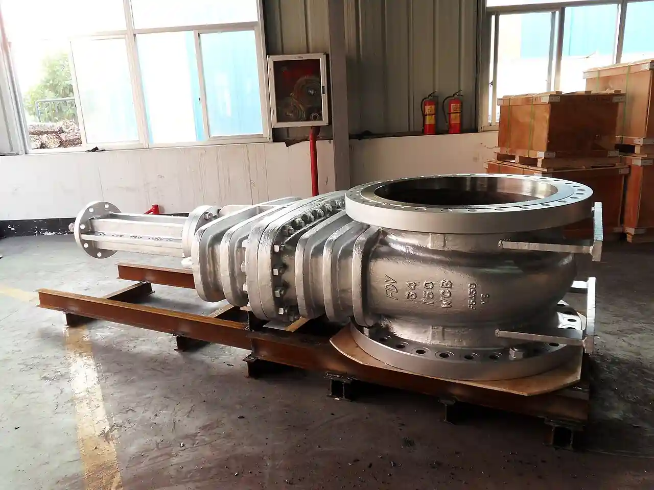
A slam-shut valve is an automatic safety shut-off device installed in a gas pressure regulating station or gas pipeline, held open against a spring or actuator charge by line pressure sensing, and designed to close fully within seconds when the monitored pressure moves outside a set band. It exists to isolate: when a regulator fails open, a downstream pipe ruptures, or supply pressure collapses, the slam-shut valve trips and cuts the gas flow, and it stays closed until a person walks up and resets it by hand. In European gas practice it is defined as a safety device under EN 14382, installed upstream or in series with a pressure reducing valve inside the station, with overpressure protection, labelled OPSO, and underpressure protection, labelled UPSO, as its two trip directions. Sizes commonly run from DN 25 to DN 300, pressure classes from PN 16 to PN 100 with ANSI Class 150 to 600 equivalents, and rated inlet pressures from a few bar up to 100 bar in distribution and transmission duty.
Procurement engineers meet this valve wherever a gas utility, an industrial gas consumer, or a power plant takes gas from a network at one pressure and delivers it at a lower one. The decision this page settles is narrow and practical: which trip set points and accuracy class the station actually needs, which body style, axial-flow sleeve, disk, or wafer, fits the piping and the flow, how the valve resets and signals, and what belongs in the RFQ so the shipped device matches the station design. The answer lands as a line set: size and class, monitored pressure range, OPSO and UPSO set points, accuracy class, body style, reset type, and accessories. Every chapter below feeds that line set so the isolation layer is bought on evidence, not on a brochure photograph.
This page treats the slam-shut valve as a purchasing object: what EN 14382 demands of a safety shut-off device, how OPSO and UPSO set points and accuracy classes translate into datasheet rows, which body styles suit which flow conditions, and how trip, reset, and signaling options combine into a defensible RFQ for a gas regulating station. It is written for engineers who issue purchase specifications, not for readers who want a brochure summary.
Chapter 1 / 06
What a Slam-Shut Valve Is and What Is Being Decided
The definition is functional, not geometric. A slam-shut valve, abbreviated SSV in gas industry documents, is a valve whose only designed action is to move from fully open to fully closed, quickly, on command of a pressure sensing element, and to remain closed without external energy until deliberately reset. It does not modulate. It does not throttle. It does not relieve excess pressure to atmosphere; that duty belongs to a safety relief valve, which opens proportionally or fully to vent a surge and then re-closes. The slam-shut valve instead stops the flow dead so that the downstream pipework, the regulator station internals, and the customer installation are cut off from the fault. In a station drawing, it appears in series with the gas pressure regulation train, usually upstream of the active and monitor regulators, sensing pressure through an impulse line on the downstream side or on its own inlet.
What is actually being decided in this purchase is the credibility of the last automatic layer in the station. A pressure reducing valve controls pressure continuously and, like any controller, can fail: a worn diaphragm, a stuck pilot, a linkage jam at full open. The station then delivers inlet pressure to a downstream system rated far below it. The slam-shut valve is the device that must trip under exactly those degraded conditions, close against full line differential, and hold tight. The buyer commits to a set point band, an accuracy class that says how tightly the device will honor that band, a response time, and a construction that survives the gas composition. A device chosen only on body size will trip at the wrong pressure or refuse to trip at all; a device chosen only on price often carries neither the certified accuracy class nor the closure test evidence that a gas utility audit will ask for.
The family context matters because the station is a chain of single-purpose devices and the SSV must not be confused with any of them. The pressure reducing valve is the continuous controller. The safety relief valve vents surges in closed vessels and low pressure mains. A rupture disk bursts once and is replaced. The tank blanketing valve and the pressure vacuum relief valve guard storage tanks against vacuum and overpressure in tank farm service. A changeover valveswitches duty between parallel regulator runs. Line isolation between stations is the work of a gate valve or a ball valve, and venting during maintenance is the work of a globe valve bleed; a butterfly valve often serves the large diameter station inlet, a check valve keeps bypass runs honest against reverse flow, a solenoid valve executes the remote vent or trip commands, and a flame arrester guards any atmospheric vent on the skid. The slam-shut valve is the only member of this chain whose function is automatic full isolation on an out-of-band pressure, and whose reset is deliberately manual. That manual reset is a feature, not a limitation: a station that re-pressurizes itself while the fault is unrepaired is a station designed to repeat its accident.
Standards organize the datasheet. EN 14382, Gas pressure regulators and associated safety devices for gas transmission and distribution, is the governing product standard for slam-shut valves in European service: it defines the accuracy class, sometimes labelled AG or SG in manufacturer datasheets, as a percentage of the set pressure within which the device must trip, and it fixes type tests for closure, leakage, and endurance. The Pressure Equipment Directive 2014/68/EU, PED, controls the pressure boundary and the category or sound engineering practice route. Regulator performance in the same station is standardized by EN 334, which is why station documents quote both standards side by side. Face-to-face and flange drilling follow EN 1092 or ASME B16.5 depending on the flange specified, and the companion flange hardware, the gasket, and the pipe fitting impulse lines are all part of the purchase package in practice. A datasheet that quotes none of these four references is a price tag, not a specification.
The RFQ should also name the sensing and signaling environment. A station built for remote operation will ask the SSV for a limit switch or proximity sensor that reports the tripped state to the SCADA layer, and sometimes for a solenoid or motorized remote trip so a control room can isolate without sending a person. Hazardous area installations, common in town border and city gate stations, carry ATEX or IECEx requirements on any electrical accessory. Stating these in the RFQ, with the gas family and the dew point or filtration quality available at the station, lets one supplier match the controller, the elastomers, and the certifications in a single pass instead of four arguments at delivery.
Chapter 2 / 06
How the Trip Mechanism Works
Mechanically the valve is a spring-loaded shutter held by a latch. In the axial-flow sleeve design, the moving element is a cylindrical sleeve that slides along the flow axis; in the disk design it is a disk or plate that drops across the bore. While the monitored pressure sits inside the permitted band, line pressure admitted through an impulse port acts on a sensing diaphragm or piston, and the force balance holds a trip latch engaged. When pressure rises past the OPSO set point or falls below the UPSO set point, the balance tips, the latch releases, and the main spring drives the sleeve or disk onto its seat without any external power. Closing times quoted by major manufacturers are typically in the range of half a second to two seconds for distribution sizes, fast enough to protect downstream equipment rated for the lower pressure, and slow enough not to behave like a bursting device in its own right.
The sensing logic deserves the buyer's closest attention because the two trip directions answer different failures. Overpressure protection, OPSO, is set above the maximum expected operating pressure and below the weakest downstream rating; it answers the failed-open regulator, the wrongly set monitor, and the thermal spike in an isolated liquid-free gas line. Underpressure protection, UPSO, is set below the minimum normal operating pressure; it answers downstream pipe rupture, a wide-open offtake, and supply collapse, any condition that would let a regulator run away or a flame go unstable at the burner. A station may need both, one, or neither depending on the safety study, and the set points must be stated with their tolerance band, because an accuracy class of five percent on a 4 bar system is a 400 mbar window, and that window decides whether nuisance trips are a monthly event or never.
The controller that houses the diaphragm, the springs, and the latch may be built into the valve body, integral, or mounted beside it as an external pilot connected by impulse tubing. Integral controllers make for a compact, single-certificate device and dominate small distribution skids. External controllers expose the set point adjustment under a sealed cover, make field verification easier, and allow the sensing point to sit downstream of the regulator train where the protected pressure actually lives. Either way, the impulse line is part of the safety function: it must be short, protected, fitted with a filter or sintered restrictor where gas quality is poor, and isolated with a small ball valve or needle-type shutoff for test purposes, and its tubing material appears in the station bill of materials like any other pipe fitting.
Reset is deliberately manual and deliberately local. After a trip, the operator bleeds the intermediate volume or equalizes pressure across the seat, cocks the sleeve or disk back against the spring until the latch re-engages, often with a lever, handwheel, or reset screw on top of the body, and only then does the valve present as open again. Some constructions allow reset only when downstream pressure is first restored to a defined fraction of inlet, a feature called controlled or pressure-dependent reset that prevents slamming gas into an empty network. Emergency manual trip is the mirror function: a button or lever that dumps the latch on purpose, giving operators a local isolation means that behaves like a fast, tight shutoff regardless of the line breakaway torque a gate valve would need. Both functions, trip and reset, should be demonstrated at commissioning with the station witnessed, because a latch that resets without full engagement is a latent refusal to trip.
Two performance numbers decide whether the installed valve actually protects. The first is closure tightness: EN 14382 classifies leakage through the seat of a closed SSV, and a utility will specify the class that matches its lost-and-unaccounted-for gas targets. The second is dynamic response under flow, because the catalogue trip time measured at no flow can stretch when the valve closes against a live stream and the decelerating gas column loads the disk. Ask for the certified trip time at maximum flow and at maximum differential, not the best case, and record it as the number the protection study relies on. A pressure transmitter or pressure gauge on either side of the SSV, and a pressure switch where the trip state must alarm, complete the measurement picture that turns a mechanical device into an auditable safety layer.
Chapter 3 / 06
Body Styles, Controllers, and Construction
Three body architectures cover the catalog landscape. The axial-flow sleeve valve carries gas straight through a cylindrical cage, and the sliding sleeve cuts flow uniformly around the full circumference as it closes; pressure recovery is good, turbulence is low, and the construction suits larger flows and transmission-adjacent duty. The disk or plate valve drops a door across the bore; it is compact, often cheaper, and standard in small distribution and industrial service. The wafer construction fits between pipeline flanges without its own end flanges, saving length and weight where station real estate is tight, and it depends on the companion flange and bolt set for its pressure boundary. Each architecture can be built to the same EN 14382 class, so the choice is driven by flow, space, and maintenance access rather than by safety grade.
Materials follow the gas and the climate. Bodies are ductile or cast steel for the common distribution range, with wrought steel or forged bodies at the top of the pressure range and aluminum bodies appearing in some lightweight town-border units. Elastomers and soft seats are the chemical decision: nitrile suits natural gas with typical aromatics, fluorocarbon grades suit higher aromatics and hot service, and hydrogen or biomethane blends push toward specified hydrogen-compatible compounds and, for metal parts, materials with adequate fatigue behavior under the smaller molecule. Low-temperature sites, or gas with high dew point depression demands, specify extended-temperature elastomer kits. The seat and seal stack is where hydrogen blending questions concentrate: a blend fraction that was irrelevant ten years ago is now a line item in the RFQ, and manufacturers answer it with a declared blend range, not a yes.
Internal controller options divide along set point ranges and adjustability. A single-range controller covers one monitored band and is ordered against the station's actual operating pressure; multi-range or spring-set-changeable controllers cover several bands with replaceable spring kits, which suits panel builders and utilities that stock one device for many stations. Adjustable set point under a sealed cap suits commissioning; fixed factory-set set points with a lead seal suit custody-adjacent installations where nobody in the field should be able to move the protection band. The trip state signaling options run from a purely visual flag, through mechanical limit switches, to inductive sensors for hazardous areas, and remote trip solenoids exist for stations integrated into remote control schemes. Every electrical accessory inherits the area classification, so the Ex certificate list in the RFQ must include the accessories, not just the valve.
The duty map below consolidates the body style decision into one table a specifier can scan before writing the RFQ; it pairs common station services with the construction that survives them.
Station service
Suitable construction
Notes on the choice
Town border station, DN 50 to DN 100, medium to low pressure cut
Disk or axial sleeve, integral controller, OPSO plus UPSO
Both trip directions typical; compact skid layout favors integral sensing
City gate or transmission tap, DN 150 and larger, high pressure
Axial-flow sleeve, external controller, welded or flanged ends
Low pressure loss matters at flow; certified trip time at flow required
Industrial customer line feeding boilers or burners
Disk valve, OPSO with wide band, burner management interlock
UPSO often set to protect against flame loss induced underpressure
Material and fatigue declarations requested in the RFQ
Compact meter and regulator cabinet
Wafer body between companion flanges
Verify flange, gasket, and bolt set in the same purchase
Remote or unattended station
Trip state sensor plus optional remote trip solenoid, Ex rated
Manual reset still required on site by design
Boundaries are worth stating bluntly. This valve does not replace a safety relief valve, because isolating a closed volume that is already overpressure does nothing to reduce its pressure, and venting is the remedy there. It does not replace the monitor regulator, which limits pressure continuously in a standby sense. It is not a lock-up device in the regulator sense; lock-up is the pressure reducing valve's own tight shutoff at zero flow. And it is not an emergency isolation valve for maintenance: that duty belongs to a full-bore ball valve or gate valve that a person operates, because the SSV is not designed for frequent cycling and its seat life is measured in trips, not in decades of daily operation. The last point surprises buyers who conflate the SSV with an automated isolation valve; the correct instrument for that duty, if a quarter-turn actuated device is wanted, is a ball valve with an actuator, or where line breaking must also vent, a changeover valve arrangement in the station design.
Chapter 4 / 06
Key Specification Parameters
The table below decodes the datasheet lines that decide whether a quoted device matches the station. Each row is a purchase defining parameter; the paragraphs after the table explain what to demand and what a weak answer looks like.
Attribute
Typical range or options
What it decides
Nominal size
DN 25 to DN 300; larger by project
Flow capacity, station layout, face-to-face length
Pressure class and rated inlet
PN 16 to PN 100; ANSI CL150 to CL600; inlet to 100 bar
Pressure boundary, PED category, flange rating
Trip directions
OPSO only, UPSO only, or both
Which failures the station is protected against
Set point ranges
Per controller spring set, e.g. 30 to 400 mbar up to bar level bands
Where the protection band sits inside the operating envelope
Accuracy class
EN 14382 classes, commonly 2.5 to 10 percent of set point
Tolerance window honored at trip; nuisance trip risk
Response time
Typically 0.5 to 2 s, certified at flow
Pressure rise the downstream system sees before isolation
Seat leakage class
EN 14382 closure tightness grades
Gas loss and lockdown credibility after a trip
Body style
Axial-flow sleeve, disk, wafer
Pressure drop, space, maintenance access
Controller
Integral or external; fixed or adjustable set point
Sensing location, field verification, commissioning
Reset and emergency trip
Manual lever or screw; optional controlled reset; manual trip button
Natural gas families, blends, LPG air; minus 20 to 60 deg C typical, wider on request
Elastomers, materials, fatigue declarations
The accuracy class row deserves its own paragraph because it is the row most often quoted loosely. EN 14382 expresses accuracy as a percentage band around the set point within which the device will actually trip under certification conditions. A class 5 device set at 100 mbar UPSO may trip anywhere between 95 and 105 mbar on any given day, and that band must be reconciled with the minimum operating pressure and the protection target before the order, not after the first nuisance trip. Tighter classes cost more because the springs, diaphragm area, and latch geometry must be held to closer limits, and the honest question for the station study is how much of the window the downstream tolerance can absorb. Ask for the certified class per direction, because OPSO and UPSO accuracies are stated separately, and a single blended figure in a catalogue table is a sign the datasheet was written for sales rather than for procurement.
The set point table interacts with the controller spring kit in a way that catches infrequent buyers. A controller covers a finite band, for example 0.4 to 2 bar, with the set point fixed anywhere inside it by spring pretension or by a graded spring set. If the station's operating pressure later changes, the device does not necessarily follow: a new spring kit, a controller exchange, or a factory reset is needed. Utilities that standardize one device across many stations buy multi-range controllers and accept the wider accuracy band that comes with a wide spring; a single-station industrial buyer buys the narrow band that fits one system and gets the tighter trip window. The table below compresses the controller logic into the form a specification meeting can argue from.
Controller arrangement
Set point behavior
Where it earns its cost
Single band, factory set and sealed
Fixed band, lead sealed, no field adjustment
Custody adjacent stations, audit-heavy utilities
Single band, adjustable under cap
Commissioning trim inside one band
Single station industrial installations
Multi-range with spring kits
Several bands, one body, stocked springs
Utilities and panel builders serving many stations
External pilot at downstream tap
Senses protected pressure directly
Long station trains, verification access, skids
OPSO and UPSO combined stack
Two directions in one controller
Town border and city gate standard protection
The signaling rows close the specification. A visual flag tells the person standing at the station that the valve is tripped, which is still the primary interface in most gas utilities. A limit switch or inductive sensor tells the control room, and where the station is unattended, that telemetry line is the difference between a two hour response and a two day one. A remote trip solenoid lets the SCADA layer isolate the station deliberately, and it must be latching or wired so that a control power loss does not itself produce a trip unless that is the chosen fail behavior. Each accessory adds an Ex certificate in classified areas, a wiring gland entry, and a line on the commissioning checklist, and the quotation that prices the valve and leaves these as an exercise is not a complete quotation.
Chapter 5 / 06
Selection Decision Factors and RFQ Language
The decision sequence is short enough to run as a checklist in a specification meeting, and each step eliminates a class of quotations before price comparisons begin.
Fix the protection study first: which overpressure and underpressure scenarios the SSV must answer, and the downstream ratings it defends. The study, not the catalogue, fixes the trip directions.
Set the operating envelope: maximum and minimum normal pressures, then place OPSO above the maximum with the accuracy band included and UPSO below the minimum with the same margin.
Choose the accuracy class that keeps both set windows clear of nuisance and of the protected limit; note OPSO and UPSO classes separately.
Size on flow and drop: check the capacity table at station flow so the axial or disk body does not steal pressure the regulator train needs, and demand the certified trip time at that flow.
Match materials to the gas: family, blend fraction including hydrogen or biomethane if present, dew point, filtration quality, and site temperature range, then read the elastomer declaration.
Fix construction: body style against space and access, controller type against verification practice, and end connections, flange standard, or weld prep against the station piping.
Specify reset and trip interfaces: manual reset always, controlled reset if the network requires staged repressurization, emergency trip lever, and the manual isolation means around the valve.
Add the electrical layer where relevant: trip state sensor, remote trip solenoid, area classification, and the certificates that go with each accessory.
Fix the verification evidence: EN 14382 type test references, PED conformity route and category, seat leakage class, and the factory or witnessed trip test at the set points ordered.
Against neighboring safety devices the comparison a specifier actually needs runs as follows, and it belongs in this selection chapter rather than in the page title. A safety relief valve answers overpressure by venting mass from a closed volume and is the correct instrument on vessels and headers; the slam-shut valve answers a moving stream by isolating it and is the correct instrument in a flowing station train. A rupture disk vents once and must be replaced, suiting isolated volumes rather than flowing lines. A monitor regulator limits pressure continuously without stopping flow, and it pairs with, rather than replaces, the SSV. A pressure switch feeding a shutdown logic can imitate the trip function only if a separate isolating valve and actuator are bought and validated as a assembly, which is precisely what a backflow style certified assembly does in the water world; in gas, buying the integrated certified device is almost always cheaper than integrating your own. Choose the layer the hazard study asks for, and let the set point mathematics, not the supplier's stock list, decide the band.
The application map below turns that logic into a table the project file can carry.
Application
Construction to specify
Check before order
Medium to low distribution cut, residential feed
Disk body, combined OPSO and UPSO controller, class 5 or better
Set windows clear of nightly load swing
High pressure city gate
Axial-flow sleeve, external controller, certified trip at maximum flow
Pressure drop at flow; closure test at full differential
Boiler or burner train isolation layer
Disk valve with OPSO, interlock to burner management
Response time against train volume
Blend or hydrogen service conversion
Declared blend range body and seal kit
Material declarations and fatigue data
Unattended remote station
Tripped state sensor plus Ex certificates, optional remote trip
Fail behavior of solenoid on power loss
Cabinet installation with tight spools
Wafer body with companion flanges
Flange drilling, gasket, and bolt set ordered together
The RFQ block should be written once and reused. A complete block reads: quantity, size, and pressure class; gas family and blend fractions including hydrogen or biomethane if applicable; design and operating pressures with temperature range; monitored pressure band and sensing point location; trip directions required with OPSO and UPSO set points and their EN 14382 accuracy classes; body style and end connections with flange standard; controller type, fixed or adjustable, and reset method including controlled reset if required; certified response time at station flow; seat leakage class; signal accessories with area classification and certificates; impulse line provisions including filtration; materials of body, trim, and elastomers; PED category and conformity route; and the test evidence to be delivered, factory set point verification and a witnessed trip test at both set points where the station warrants it. A quotation returned without the accuracy class per direction or without trip time at flow is incomplete at any price.
Chapter 6 / 06
Installation, Standards, Failure Modes, and Maintenance
Installation quality decides whether the certified trip time and leakage class survive contact with the field. Mount the valve in the orientation the manufacturer certifies; most disk designs tolerate horizontal and vertical lines with defined limits, and the controller must remain accessible for reset, which is a person with a lever, not a robot with a wrench. Impulse lines run short and protected, with the sintered filter or restriction the datasheet calls for where gas quality is variable, and with an isolating ball valve arranged so a controller can be checked without blowing down the station. Flanged joints follow the torque pattern of the flange standard used; a wafer body lives or dies by its companion flange alignment, and pipe strain bolted into the body is the most common self-inflicted cause of sticky sleeves. Leave clearance above the body for the reset stroke and the emergency trip lever, because the day the valve trips is exactly the day that access matters.
Commissioning practice protects the set points. Record the as-delivered set points against the order, then perform a witnessed trip in each required direction using the station's own bleed or a test connection, logging the pressure at which the latch released. Where the controller is adjustable, seal the adjustment after setting, and record the seal number in the station file. Verify the signaling: a limit switch that never trips the alarm is worse than none, because it manufactures confidence. Check closure tightness after the first trip by monitoring the locked-in downstream volume with a pressure gauge over a defined interval, and only then hand the station to operations. The whole procedure is an hour on site and it converts the factory certificate into station-specific evidence.
The standards set the verification frame. EN 14382 governs the device and its type tests. EN 334 governs the regulators in the same train, which is why station folders quote both. PED 2014/68/EU governs the pressure boundary and the marking. End standards, EN 1092 or ASME B16.5, fix the flange geometry, and internal transport and distribution regulations, plus the local gas utility code, typically layer inspection intervals on top. Where the station crosses into a classified area, ATEX or IECEx documentation accompanies every electrical accessory. A specification that cites these by name transfers the burden of proof to the supplier, which is where it belongs.
Failure modes in service follow a short and predictable list. Nuisance trips: set points sitting inside the accuracy band too close to real operating extremes, or a diaphragm fatigue changing the effective band; the fix is a set point study, not a stiffer latch. Failure to trip: latch contamination from dirty gas, a sleeve score from pipe debris, or an impulse line blocked, which is why gas quality filtration and line checks appear in the RFQ; the remedy is functional testing on a schedule. Seat leakage after trips: repeated dynamic closures work the soft seat, and the leakage class should be re-verified periodically on critical stations. Controller drift: springs and diaphragms age, and an annual verification against a reference gauge catches a band that has walked. Accessory faults: microswitches and solenoids fail electrically long before the valve fails mechanically, and spare kits for those accessories belong in the station spares box from day one.
Maintenance intervals scale with consequence. A distribution SSV that protects a residential network typically earns a functional trip test at the utility's mandated interval, commonly between one and five years depending on the local code, with seal and elastomer inspection at each test and a full internal inspection at major station refurbishment. An industrial burner train valve earns an annual check alongside the burner management system proof tests, because it shares interlocks with them. Every test produces a number, the actual trip pressure, and the trend of those numbers against the certified band is the real condition monitor for the device. None of these checks costs a tenth of one uncontrolled repressurization event, and every one of them feeds the next RFQ with station-specific evidence, which is how a purchasing file gets smarter instead of just older.
FAQ
How does a slam-shut valve differ from a safety relief valve?
A safety relief valve vents excess gas from a closed volume and re-closes, reducing pressure by releasing mass. A slam-shut valve isolates a flowing stream by closing fully and latching shut, and it stays closed until manually reset. In a gas regulating station the two answer different scenarios: the relief valve protects vessels and headers against surge, while the slam-shut valve protects the downstream system against a failed-open regulator or a line break, and many stations carry both devices for exactly that reason.
What do OPSO and UPSO mean and which do I need?
OPSO is overpressure shut-off, tripping when monitored pressure rises above its set point; UPSO is underpressure shut-off, tripping when pressure falls below its set point. OPSO answers the failed regulator and the wrongly configured monitor; UPSO answers downstream pipe rupture, a wide-open offtake, and supply collapse. Distribution and town border stations usually specify both directions in one controller, while an industrial burner train may only need OPSO with its interlock. The protection study for the station, not catalogue habit, fixes the answer.
Why must the valve be manually reset after a trip?
Manual reset is a deliberate safety design. The trip happened because something in the station failed or broke, and the valve keeps the system isolated until a person verifies the cause, repairs it, and consciously re-arms the latch. Automatic or remote re-opening would re-pressurize a network whose integrity is unknown, which converts one incident into two. Some designs add controlled reset that also requires downstream pressure to be restored first, staging the repressurization of an emptied network.
What response time should I demand?
Ask for the certified trip time at your station's maximum flow and full differential, not the catalogue no-flow figure. Distribution sizes typically close within about half a second to two seconds. What matters is the pressure rise the downstream system experiences during the closing interval, which the protection study computes from train volume and inflow; the order should state the required closing time and require the test evidence at conditions, because a valve that closes acceptably on the bench can behave differently against a live stream.
What does the EN 14382 accuracy class mean in practice?
The class is a percentage band around the set point inside which the certified device will trip. A class 5 device set at 100 mbar may trip anywhere between 95 and 105 mbar, so the band must fit between your minimum normal pressure and the protected rating with margin on both sides. Tighter classes cost more because springs, diaphragm areas, and latch geometry are held closer. OPSO and UPSO accuracies are certified separately, and the quotation should quote both, because a single blended number is a sales figure, not a specification.
Can the same valve serve hydrogen or biomethane blends?
Only if the manufacturer declares the blend range. Hydrogen raises permeation and fatigue questions for elastomers and thin metal sections, and biomethane brings trace constituents that attack some compounds. The RFQ should state the gas family and the blend fraction, and the answer should be a written declaration of compatible materials for that fraction, not a general gas suitability claim. Utilities converting distribution networks increasingly order declared blend-capable devices even where the blend arrives years later.
How often should a slam-shut valve be tested?
Follow the local gas code first; where it leaves the interval open, distribution practice commonly lands between one and five years for a functional trip test, with elastomer and seal inspection at each test and full internal inspection at station refurbishment. Industrial burner train valves are usually checked annually alongside burner management proof tests. Log the actual trip pressure at every test; the drift trend against the certified accuracy band is the real condition indicator, and it tells you the exact date the device started asking for service.