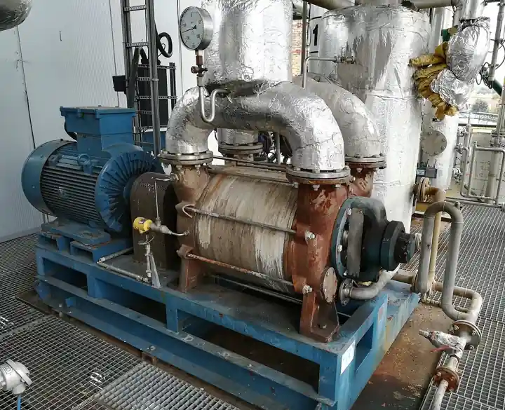
A liquid ring vacuum pump is a positive displacement machine that uses a rotating ring of service liquid, almost always water, as the sealing and compressing element. A multiblade impeller sits eccentrically inside a cylindrical casing; when it spins, the liquid is thrown outward into a ring against the casing wall, and the chambers between blades grow and shrink as they travel the eccentric space. Gas drawn into the growing chambers is trapped, transported, and expelled at higher pressure, the liquid ring doing the work of pistons, seals, and valves at once. Compression is close to isothermal because the ring absorbs the heat continuously.
Procurement engineers meet this machine wherever the gas is wet, condensable, corrosive, or loaded with carryover: crude vacuum distillation overhead, paper machine dewatering, steel degassing backing stages, power plant condenser exhausters, gypsum filter drawers, food deaeration, and medical vacuum. The decisions that land on a buyer are four: single stage or two stage, what ultimate vacuum the seal liquid temperature really permits, once through or recovered seal liquid, and cast iron or alloy construction. This page works each decision the way a specification engineer has to: with numbers, standards, and RFQ language that survives supplier review.
This page decodes the liquid ring vacuum pump as a purchasing object: how seal liquid vapor pressure sets the vacuum floor, what two stage construction and an air ejector buy, how HEI test data and API 681 packages differ, and how to write an RFQ that pins capacity, seal liquid flow, and materials. It is written for engineers who issue specifications.
Chapter 1 / 06
What a Liquid Ring Machine Is and What Is Being Decided
The liquid ring vacuum pump occupies a specific corner of the vacuum equipment map: it is the machine you buy when the gas stream is hostile to precision machinery. Oil sealed rotary vane pumps reach deeper vacuum on clean dry loads but lose their oil to condensed vapors and corrosive attack. Dry claw and dry screw designs keep oil out of the gas path, at a price and a sensitivity to entrained solids. Steam ejectors have no moving parts but demand high pressure motive steam and cooling water in quantity. The liquid ring machine accepts a wet, condensable, fouling stream because the service liquid continuously flushes the working chamber, and the same liquid absorbs compression heat, so discharge temperatures stay within roughly 5 to 15 deg C of the incoming seal liquid.
What is being decided at purchase time is therefore not simply "a vacuum pump". The buyer commits to four positions at once. First, depth of vacuum: a single stage machine bottoms out near 50 to 70 torr in practice with 15 deg C seal water, a two stage machine reaches roughly 25 to 35 torr, and neither can beat the vapor pressure floor set by seal liquid temperature. Second, the seal liquid circuit: once through, partially recovered, or closed loop with a heat exchanger. Third, the materials class: cast iron for general service, 316L stainless steel for corrosive duty, duplex 2205 for high chloride and sour service. Fourth, the procurement frame: an industrial package tested to the Heat Exchange Institute standard, or an API 681 special purpose package for refinery service with rotordynamic analysis and documented spares.
The boundary against neighbors is worth one more paragraph because mislocated orders are expensive. If the duty is clean, dry, and below 1 torr, this is the wrong family; a roots booster over a dry backing pump serves semiconductor, metallurgy, and freeze drying duty far better. Small laboratory duties at 0.01 torr still belong to the oil sealed vane on cost. Where 10 bar steam and cooling water are abundant and the load enormous, a steam ejector stage over condensers with liquid ring backing is the most robust architecture, which is how most crude vacuum towers are built. The liquid ring machine wins where the load is condensable or wet, where maintenance skill is general purpose, and where tolerance for entrained liquid slugs and fiber is a requirement rather than a defect.
Application scale spans three orders of magnitude: a packaged food deaeration unit may carry a 2.2 kW close coupled machine moving 60 m3/h at 100 mbar; a paper machine dewatering system runs banks of 75 to 200 kW machines across couch and flat box headers on air that carries water, fiber, and sizing chemicals continuously; a crude vacuum system backing ejector stages moves tens of thousands of m3/h of hydrocarbon saturated overhead at 40 to 80 mbar. The specifying language differs across that range, but the physics on this page does not.
One framing analogy helps mechanical buyers: inside the package, the ring is the compressor element, while the seal liquid circulation is a pump loop with a heat exchanger, a separator, and valves, sized with the same velocity, NPSH, and materials logic as any centrifugal pump installation in the same plant. Engineers who treat the liquid circuit as a piping afterthought buy cavitation problems; chapter 6 returns to this with numbers.
Chapter 2 / 06
How the Liquid Ring Compresses Gas
The mechanism is geometric. The impeller blades rotate about a shaft offset from the casing centerline by the eccentricity. Centrifugal force pins the service liquid against the casing bore, and because the shaft is offset, the free surface of the liquid ring sits closer to the hub at the top of the casing and further at the bottom. Each interblade chamber starts at the suction port with a large volume as the liquid recedes from the hub, fills with gas, then the liquid returns toward the hub as the chamber travels to the discharge port, shrinking the volume and raising the gas pressure before release. The ports are machined into the port plates; there are no valves.
Because the liquid surface directly contacts the gas throughout the cycle, compression is effectively isothermal: nearly all the heat of compression plus friction power transfers into the service liquid. Three practical consequences follow. Discharge gas temperature stays close to discharge liquid temperature, protecting temperature sensitive processes and recovered solvents. The service liquid carries away on the order of 90 percent of absorbed shaft power as heat, so the closed loop cooler is sized on shaft power rather than gas flow. And condensable vapors can condense inside the working chamber mid stroke, reducing discharged volume and raising apparent capacity; chapter 5 treats this as a selection factor rather than a curiosity.
Capacity and power are functions of suction pressure, and a serious datasheet states them as curves, not single points. Displacement is swept volume times speed; actual capacity is lower once slip, clearance gas, and vapor effects are counted. As suction pressure falls, gas density falls with it, so capacity in standard volume terms drops while volume flow at suction conditions stays roughly flat, and gas power peaks somewhere mid range before falling again at deep vacuum. Motor sizing must cover the worst point of the power curve, not the nameplate flow point. Where process turndown matters, a VFD on the motor moves capacity roughly proportional to speed within the machine's limits and softens start current; chapter 4 folds this into the motor and starter rows.
The vacuum floor is thermodynamics, not manufacturing tolerance. The lowest pressure the ring can sustain cannot fall below the vapor pressure of the service liquid at its temperature, because the liquid boils into the low pressure chamber until equilibrium. Water at 15 deg C has a vapor pressure of 17 mbar, about 13 torr; at 25 deg C it is 31.7 mbar or 24 torr; at 35 deg C it is 56 mbar or 42 torr. A two stage machine concentrates the cold, freshly supplied liquid in the first stage and lets the second stage work against gas already compressed above the floor; this is why two stage designs reach 25 to 35 torr with 15 deg C water while single stage designs stall near 50 to 70 torr, where the discharge port sits at the hottest liquid in the machine. Warm plant water in summer routinely erases 10 to 20 torr of depth; the exact penalty is the vapor pressure curve, tabulated in chapter 4.
Cavitation is the failure mode that gives this machine family its sizing rules. If the process demands suction pressure below what the ring liquid can sustain at its local temperature, the liquid flashes to vapor inside the chambers, the pumping action collapses, and the impeller runs in a two phase churn that sounds like gravel circulating. Sustained cavitation erodes blade edges and port plates within weeks and hammers bearings. The defense is a margin rule: keep the specified suction pressure at least 10 to 15 mbar above the seal liquid vapor pressure at its warmest expected condition, or install an air ejector or booster upstream that lets the ring operate at a comfortable 30 to 60 mbar while the process sees single digit torr. Cold make up water, a larger cooler, or a two stage machine are the other standard moves, in rising order of capital cost.
Two stage interstage geometry and the air ejector option deserve precise language because datasheets blur them. In the two stage pump, the first stage discharges into the suction of the second internally, with fresh liquid admitted to both; the gain in depth is real but bounded by the same vapor pressure physics. An air ejector is a venturi nozzle upstream of the pump suction, motivated by a small bleed of compressed air routed from the discharge side; it pulls the process side to 5 to 10 torr while the pump itself never sees below 20 to 30 torr. Ejector assisted packages are standard in condenser exhauster service, and the RFQ should state whether the quoted capacity curve includes the ejector motive gas, because the two readings differ by exactly the motive flow.
Chapter 3 / 06
Types, Construction, and Duty Boundaries
Single stage machines are the volume product: simpler, cheaper per kW, tolerant of liquid slugs, and adequate for every duty that bottoms above roughly 60 torr. Within single stage, manufacturers distinguish conical and flat port plate designs; conical ports suit condensable and liquid carrying service, while flat port plates suit dry gas and recover slightly better efficiency. Two stage machines stack a low pressure and a high pressure stage on one shaft; they buy the 25 to 35 torr class and flatter capacity curves at deep suction, at roughly a 30 to 60 percent capital premium and a stricter attitude toward fouling liquids.
The seal liquid circuit is the second axis, and it is a plant engineering decision more than a pump decision. Once through service, from a cooling water header to drain, gives the coldest liquid, the deepest vacuum, and the simplest hardware, at the cost of continuous water consumption and a treatment liability for the contaminated stream. Partial recovery recirculates most of the liquid, bleeding and making up perhaps 20 to 50 percent. Closed loop systems run the whole seal flow through a heat exchanger against a glycol or cooling tower utility, add freeze protection and a biocide regime, and turn the package into a small utility plant; chapter 6 prices the maintenance consequences. Corrosive or brine service may change the working fluid itself, for example concentrated sulfuric acid as the ring liquid in chlorine compression service, which drives materials to high alloys and fixes the shaft sealing plan.
Materials follow the liquid and the gas together. Cast iron, with its graphite bearing behavior and vibration damping, is the baseline for water ring service on non aggressive gas. 316L stainless steel construction is the standard answer for chlorides below pitting thresholds, food and pharmaceutical washdown, and corrosive off gas; duplex 2205 appears where warm chloride or sour, H2S bearing service would pit and stress crack 316L. Shafts run 17-4 PH or duplex stainless; elastomers are specified FKM or EPDM against the actual chemical list, never generically. Where the gas is chlorine, the ring liquid is usually 96 to 98 percent sulfuric acid and the entire wetted path is high alloy or lined construction, a specialty corner with a short qualified supplier list.
The package around the ring is where most procurement mistakes hide. The discharge side carries an entrainment separator; the recirculation loop, on closed systems, carries a pump selected with the same rules as any centrifugal pump installation: curve against system resistance, NPSH margin against the warmest liquid, materials matched to the chemistry. Chemical treatment of the closed circuit, biocide and pH control against algae and scale, is dosed by a small metering pump from a day tank; on brine or scrubber linked circuits, a magnetic drive pump moves corrosive make up without a dynamic seal to leak. Downstream of the process, a progressive cavity pump suits the thickened fiber sludge from a paper dewatering separator, and a lobe pump running as a blower is the classic upstream booster stage when the system needs an intermediate pressure leg.
Duty boundaries close the type picture. The liquid ring machine is not a fine vacuum instrument: below roughly 20 torr with water, physics wins regardless of build quality. It is not oil free in the strict sense: discharge carries liquid mist and traces of whatever the liquid has absorbed, which is why strictly oil free applications move to dry screw. It tolerates, better than any competitor, slugs of condensate, fiber, and soluble solids, which is why paper, gypsum, food, and vacuum filtration remain its home ground. The table below fixes the boundaries in a form a specifier can lift into a technical inquiry.
Configuration
Practical ultimate vacuum, 15 deg C water
Typical capacity range
Seal liquid circuit
Best duty fit
Single stage, conical port, cast iron
50 to 70 torr
30 to 30,000 m3/h
Once through or partial recovery
Paper dewatering, filter drawers, general plant vacuum
Single stage, 316L wetted
50 to 70 torr
30 to 5,000 m3/h
Once through or closed loop
Food deaeration, pharmaceutical washdown, mild corrosive off gas
Two stage, cast iron
25 to 35 torr
60 to 4,000 m3/h
Closed loop preferred
Condenser exhausters, degassing backing, deep process vacuum
Two stage, duplex 2205 wetted
25 to 35 torr
100 to 3,000 m3/h
Closed loop
Sour and high chloride refinery and VRU service
Single stage with air ejector
5 to 10 torr at process
30 to 2,000 m3/h
Once through or closed loop
Condenser air removal, lab and pilot deep vacuum without dry pumps
Acid ring, chlorine service
100 to 300 torr
50 to 2,500 m3/h
Concentrated acid, closed
Chlorine compression and tail gas, specialty suppliers only
Chapter 4 / 06
Key Specification Parameters
The datasheet rows that decide whether a quoted machine matches the service are consolidated below, followed by the seal liquid temperature table that converts plant water reality into achievable vacuum. A quotation that does not state capacity at a named suction pressure and a named seal liquid temperature is not comparable to one that does, and should be returned.
Attribute
Typical range or options
What it decides
Capacity at suction pressure
30 to 30,000 m3/h, quoted at stated torr or mbar
Whether the machine holds process pressure at the design load; the single most misquoted row
Ultimate vacuum
Single stage 50 to 70 torr; two stage 25 to 35 torr; ejector assisted 5 to 10 torr, all at 15 deg C water
Depth floor of the whole vacuum system against the seal liquid temperature actually available
Seal liquid flow and temperature
Roughly 1 to 2 percent of displacement volume as vendor curve; 10 to 35 deg C design point
Heat removal, achievable vacuum, and utility consumption of the circuit
Motor power
1.1 to 400 kW, sized on the peak of the power curve
Energy cost and starter architecture; undersized motors trip at mid range suction, not at full load
Wetted materials
Cast iron, 316L stainless steel, duplex 2205; 17-4 PH or duplex shaft; FKM or EPDM elastomers
Corrosion life against gas chemistry and seal water quality
Shaft sealing
Lip seals, packed gland, or mechanical seal with quench on corrosive duty
Leak rate, maintenance access, and containment classification of the package
Performance test basis
HEI Performance Standard for Liquid Ring Vacuum Pumps
Acceptance tolerance applied to capacity and power at witness test
Package class
General industrial skid, or API 681 special purpose
Rotordynamic documentation, lube system, spares philosophy, and price class
The seal liquid temperature row deserves its own table because it is the silent killer of commissioning schedules. Water vapor pressure sets the floor; achievable suction sits a working margin above it. Plant cooling water at 30 deg C in summer is not the 15 deg C catalog condition. The table gives planning numbers for a competent two stage machine; single stage machines sit 25 to 35 torr higher at every row.
Seal water temperature
Water vapor pressure
Achievable suction, two stage
Comment for the specification
10 deg C
12.3 mbar / 9.2 torr
About 22 to 30 torr
Chilled water buys little beyond this; usually not worth the plant
15 deg C
17.0 mbar / 12.8 torr
25 to 35 torr
Catalog reference condition; quote all curves here
20 deg C
23.4 mbar / 17.5 torr
30 to 42 torr
Typical temperate surface water without a cooler
25 deg C
31.7 mbar / 23.8 torr
38 to 50 torr
Closed loop with undersized heat exchanger lands here
30 deg C
42.5 mbar / 31.8 torr
48 to 65 torr
Summer cooling tower water; verify against process demand
35 deg C
56.3 mbar / 42.2 torr
62 to 80 torr
Two stage premium is mostly wasted; single stage may suffice
Shaft sealing and the small bore trim complete the parameter story. On clean water ring service, lip or packed seals last years; on corrosive or sour service the shaft line gets a mechanical seal, often with a quench arrangement, because a weeping gland on sour water is a personnel issue rather than housekeeping. The make up connections are where the package meets the plant: a check valve in the seal water make up line stops siphoning back through the pump at shutdown, a Y strainer on the same line protects the ring and separator nozzles from scale and debris, and stainless steel piping on the wet path is cheap insurance against twenty years of chloride micro leaks. Motor starting is a line item with electrical consequences: across the line, star delta, a soft starter that limits inrush on larger frames, or a VFD where process turndown justifies the harmonics review.
Chapter 5 / 06
Selection Decision Factors and RFQ Language
The selection sequence runs as a checklist, and each step eliminates a class of quotations before price comparison begins.
Fix the process requirement at the ring suction flange: pressure under peak load, gas composition including condensables and corrosives, and arriving gas temperature.
Fix the worst case seal liquid temperature from plant utility data, summer cooling tower or exchanger outlet, not the annual average.
Read achievable vacuum from the temperature table; add a stage or ejector if the margin is under 10 mbar.
Classify the load: wet and condensable favors the liquid ring; dry clean loads at depth favor dry screw or claw; oil sensitive product contact favors oil free architectures.
Choose the circuit on water balance, discharge permit, and freeze exposure rather than first cost.
Set materials from the chemistry of both gas and liquid, including cleaning chemicals on food duty.
Size the motor on the power curve peak and set starter policy: direct or star delta on small frames, a soft starter on medium frames, a VFD where load swings widely.
Decide the procurement class: HEI tested industrial package, or API 681 with data books, rotordynamics, and spares.
Condensable versus dry load is the first technical fork. When the stream carries a large water or solvent vapor fraction, vapor that condenses inside the chamber mid stroke reduces displaced volume and apparent capacity rises; a machine sized only on dry air equivalence can end up oversized, and one sized on total mixture flow can hold process pressure better than its dry rating suggests. Suppliers correct with capacity curves plotted against vapor fraction or inlet temperature; the RFQ should present the load honestly as gas plus vapor streams with temperatures and let the vendor apply the correction. A stream that is mostly non condensable inleakage air, as in condenser exhauster duty, sizes directly on the air curve, and the classic error there is forgetting the ejector motive gas when one is fitted.
The comparison to competing technologies belongs exactly here, woven into the decision. Against an oil sealed rotary vane machine, the liquid ring accepts vapor and corrosives that would destroy vane oil but cannot match vane depth below 1 torr on clean dry loads. Against dry claw and dry screw machines, it is heavier on utilities but far more forgiving of slugs, fiber, and soluble solids, and it returns no oil aerosol to the product; oil free solvent recovery is dry screw territory. Against steam ejectors, it demands electricity and cooling but no 10 bar steam main; where an intermediate pressure leg is needed, a roots booster, which is a lobe pump running dry as a blower, sits between process and ring. Around the skid, the neighbors are ordinary fluid machinery: lube oil transfer on the API package runs through a small gear pump, chemical unloading into the treatment skid is a diaphragm pump, and routine sampling and dosing streams use a peristaltic pump whose tube is the only wetted part. Specifying these with the same discipline as the vacuum machine is what makes the skid commission cleanly.
The application table maps the common duties onto configurations; it is the fastest defensible pre RFQ screen.
Application
Required pressure at ring
Recommended configuration
Notes that change the quote
Paper machine dewatering, couch and flat boxes
300 to 500 mbar absolute
Single stage, conical port, cast iron, partial recovery
Fiber tolerant ports; capacity reserve for head breaks
Crude vacuum tower backing
40 to 120 mbar absolute
Two stage or ejector hybrid, API 681 package
Hydrocarbon saturated gas; seal liquid contamination plan
Power plant condenser exhauster
30 to 80 mbar absolute
Two stage with air ejector, 100 percent or 50 percent standby
Air inleakage sizing basis; dissolved oxygen warranty
Steel degassing backing stage
5 to 20 mbar at ring suction
Two stage plus roots booster upstream
Booster staging set by vessel volume and pump down time
Gypsum and mineral vacuum filtration
200 to 400 mbar absolute
Single stage, cast iron or 316L, once through or recovery
Scale and chloride content of filtrate drive materials
Food and pharma deaeration
50 to 150 mbar absolute
316L or duplex wetted, closed loop, clean in place capable
Surface finish and elastomer certificates join the RFQ
Vapor recovery, sour or high chloride
60 to 200 mbar absolute
Duplex 2205 two stage, mechanical seal with quench
NACE materials review; flare or vent integration
Laboratory and pilot deep vacuum
5 to 20 torr
Two stage with ejector, small frame
Compare honestly against dry screw before ordering
The RFQ block should be written once and reused. A complete block reads: quantity and duty, continuous or standby; required suction pressure at the process vessel and allowed line losses; gas composition with vapor fractions, temperatures, and design inleakage; seal liquid identity, flow, and worst case temperature; circuit type and permit constraints on discharge; wetted materials by line item; shaft sealing arrangement; motor power basis and starter type; performance test basis, HEI standard with tolerance class and witness testing; package scope, separator, heat exchanger, controls, skid, documentation; and for refinery service the API 681 data sheets. A quotation without capacity stated at the named suction pressure and seal liquid temperature is incomplete at any price, and a vendor who does not ask for vapor composition on a wet duty has not sized the machine.
Budget planning numbers, offered with the usual caution: a 5.5 kW single stage cast iron package with separator lists in the low tens of thousands of US dollars; a 75 kW two stage 316L package with closed loop cooler reaches the mid hundreds of thousands; an API 681 duplex package with data books and spares starts near the top of that band. Energy dominates life cycle cost on continuously loaded machines, which is why the power curve at the actual operating point, not the nameplate, is the economic row that matters, and why a cold, clean seal liquid circuit pays for itself in depth before it pays in maintenance.
Chapter 6 / 06
Installation, Standards, Failure Modes, and Maintenance
Installation quality decides whether the machine reaches its catalog life. Foundations carry the package weight plus the liquid fill; alignment follows coupling tolerances, because bearing load from a few tenths of misalignment at 3,000 rpm shows up as vibration within months. Suction piping slopes continuously back toward the process or to a drain pot so condensate cannot pool and slug the impeller on start; discharge piping slopes to the separator. The seal liquid supply connects through the Y strainer and the make up valve train, and the make up line carries the check valve so a shutdown cannot drain the circuit backward into the water system.
Commissioning proves the circuit before it proves the pump. Fill with the specified liquid, verify flow and temperature against the datasheet, then start. Confirm rotation, then record no load suction pressure, which should approach the datasheet ultimate vacuum at the measured liquid temperature; a machine that cannot pull its rated no load vacuum is leaking, warm, or wrong. Introduce process load gradually while listening at the casing: cavitation announces itself as a gravel churn that rises as suction pressure falls, and the commissioning record should note the suction pressure at which it begins, because that number is the real operating floor for the control system.
The standards frame is short and load bearing. The HEI Performance Standard for Liquid Ring Vacuum Pumps defines test conditions, capacity and power tolerances, and reporting forms; naming it in the purchase order is what makes a capacity guarantee enforceable. API 681 governs special purpose liquid ring packages for petroleum and refinery service: rotordynamic analysis, material documentation, engineered liquid systems, instrumentation, and spares philosophy. Between the two sits the general industrial package, built to manufacturer standards with HEI test data attached. Buyers who write "API 681" without the data book requirements get expensive industrial packages; buyers who assume API 681 from an industrial quotation get schedule surprises.
Failure modes follow a predictable short list. Cavitation erosion: blade edge and port plate gouging from running below the vapor pressure margin, prevented by ejector staging or control interlocks that raise suction set point; eroded surfaces look hammered, not corroded. Scale and fouling: hard water deposits carbonate on port plates, throttling capacity over months; the cure is chemistry, softened make up, not periodic descaling. Corrosion: chloride pitting and stress cracking of 316L in warm brine, prevented by duplex selection; below waterline corrosion of standby cast iron machines, prevented by lay up procedures. Bearing and seal wear: a rising 1x and 2x vibration signature over quarters is the classic bearing precursor, and a mechanical seal on corrosive duty is a consumable with a 24 to 36 month interval. Elastomer attack: O rings embrittled by solvent or ozone, cured by compound review against the actual chemical list.
Maintenance intervals scale with duty and circuit discipline. Daily: seal liquid flow and temperature readings, and a listen at the casing. Monthly: make up strainer cleaning in the first commissioning quarters, separator inspection, and on closed loops water chemistry sampling, drawn where the stream is corrosive with a peristaltic pump, with the treatment skid checked end to end: the day tank that a diaphragm pump fills from drums, the metering pump dosing checked against its calibration, and on brine circuits the magnetic drive pump that moves corrosive make up. Annual: coupling alignment, bearing lubrication, bolt torques, and a no load vacuum test against commissioning data; drift of more than a few torr triggers an internal inspection. On dewatering service, put the progressive cavity pump that lifts sludge from the separator on the same schedule, and on API packages the lube oil transfer gear pump on the annual list. Major overhaul at 5 to 10 years renews impeller, port plates, shaft line, and elastomers, and plants often take the chance to move large frames from star delta to a soft starter to cut inrush stress. Every one of these checks is cheaper than a vacuum loss event on a running paper machine or a condenser.
FAQ
How deep a vacuum can a liquid ring vacuum pump actually reach?
With 15 deg C seal water, a two stage machine reaches about 25 to 35 torr and a single stage machine about 50 to 70 torr. The floor is thermodynamic: suction pressure cannot fall below the vapor pressure of the seal liquid at its warmest point in the casing, about 12.8 torr for water at 15 deg C. An air ejector upstream can pull the process side to 5 to 10 torr while the pump itself stays in its comfortable range.
Why does my pump lose vacuum every summer?
Warm seal liquid raises the vapor pressure floor. Water at 30 deg C exerts about 31.8 torr versus 12.8 torr at 15 deg C, so a two stage machine that reaches 25 to 35 torr in winter lands nearer 48 to 65 torr on summer water. Fix it with colder make up, a larger heat exchanger, or ejector staging, and quote performance at the worst case liquid temperature.
What is the gravel noise in the casing, and how do I stop it?
That sound is cavitation: the seal liquid flashes to vapor inside the chambers because suction pressure has been driven below the vapor pressure at the liquid temperature. It erodes blade edges and port plates within weeks and hammers bearings. Restore margin by raising the suction set point 10 to 15 mbar above vapor pressure, cooling the liquid, adding an upstream ejector or booster, or moving to two stage construction.
Can the machine handle condensable vapors and solvent loads?
Yes, this is its home ground. Vapors that condense inside the working chamber mid stroke reduce displaced volume, often raising apparent capacity above the dry air rating, and the liquid ring tolerates liquid carryover that would destroy an oil sealed pump. Present the load as gas plus vapor streams with temperatures in the RFQ so the vendor applies the correct capacity correction, and confirm the seal liquid is compatible with the recovered solvent.
When is an API 681 package required instead of an industrial one?
API 681 applies to special purpose liquid ring machines in petroleum and refinery service, typically unspared or critical service, and it drives rotordynamic analysis, documented materials, engineered liquid systems, and a full data book. Vacuum tower backing and vapor recovery units on hydrocarbon service usually justify it. General plant vacuum, filtration, and paper duties are served by HEI tested industrial packages at a fraction of the documentation cost.
Should the seal liquid run once through or in a closed loop?
Once through gives the coldest liquid and deepest vacuum but consumes water continuously and may create a discharge permit issue as the stream picks up process contaminants. Closed loop with a heat exchanger cuts water use to make up only and stabilizes chemistry, at the cost of a cooler sized near shaft power plus freeze protection and biocide treatment. Partial recovery, roughly 20 to 50 percent bleed and make up, is the common plant compromise.
What maintenance does a liquid ring machine need?
Daily checks of seal liquid flow and temperature, monthly strainer and separator attention plus water chemistry sampling on closed loops, annual alignment, lubrication, and a no load vacuum test against commissioning data, and a major overhaul of impeller, port plates, shaft line, and elastomers at 5 to 10 years. Shaft seals on corrosive service are consumables with a 24 to 36 month interval. Records matter more here than on most rotating machines.