A gear coupling is a permanent, high-torque connection between two shafts whose teeth are constantly meshed; a clutch-brake is a pair of controlled friction or piston devices mounted on the same shaft to engage drive torque on command and arrest rotation when commanded [S1][S2][S3][S4].
Specifying the wrong one in a drivetrain is a common — and expensive — mistake: gear couplings sold as "connectors" cannot start, stop, or hold a load, while a clutch-brake sized for cyclic duty wastes money when the application is a steady-state pump, compressor, or conveyor coupling [S1][S3].
Core Function: Always-Engaged Torque Path vs On-Demand Torque Control
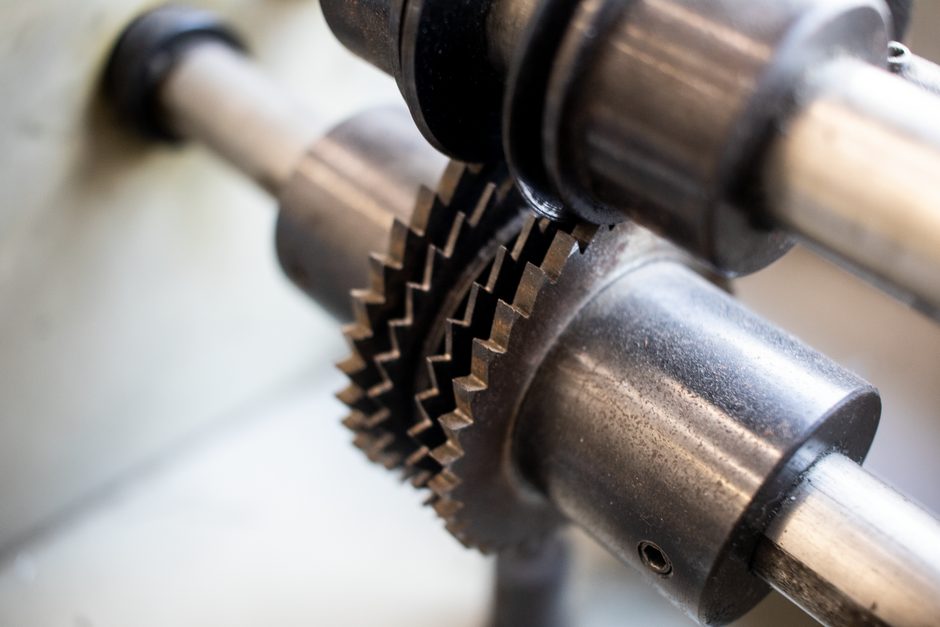
A flexible gear coupling uses two external-toothed sleeves, joined by an internal-toothed spacer (the "spider"), so torque flows continuously from driver to driven shaft while accommodating parallel, angular, and a small amount of axial misalignment [S3]. Full gear-coupling product families from manufacturers such as Nuteck explicitly cover full flexible gear couplings, chain couplings, torque limiters, and brake-drum gear couplings as permanent coupling products [S3].
A clutch-brake module, by contrast, is two separate friction devices on a common shaft: the clutch transmits torque from the input side to the load when energised, and the brake holds the load still when the clutch is released [S1][S4]. Electromagnetic disc brakes brought to rest a rotating mass such as a motor shaft on command, and piston-type units from Korean suppliers are hydraulically actuated with spring-set, hydraulically-released logic for fail-safe holding [S1][S4].
Operating State: Continuous Mesh vs Cyclic Engagement
Gear couplings run 100% engaged for the life of the machine. The teeth and the polymer or metallic spider carry load every revolution, with no wear from actuation cycles — only wear from misalignment, lubrication loss, and overload spikes [S3].
Clutch-brake units are rated by actuation cycles and by friction energy per engagement. The MathWorks drivetrain library models clutch engagement and disengagement as a discrete event with torque ramp and lock-up logic, which is exactly the cyclic engagement profile industrial clutch-brakes must survive [S2]. Hydraulic piston clutches are typically listed with MOQ and price-on-application terms, reflecting that selection is duty-cycle driven, not catalogue driven [S4].
Selection Criteria Side-by-Side
Use a gear coupling when the requirements are: (1) continuous torque transfer, (2) misalignment compensation up to the catalogue limit of the chosen size, (3) no requirement to disconnect or hold the driven shaft, and (4) minimal maintenance with grease lubrication on schedule [S3].
Use a clutch-brake when the requirements are: (1) controlled start/stop of a load, (2) positional holding between cycles, (3) repeatable indexing or press-stroke motion, and (4) fail-safe stopping when power or signal is lost — piston-type units use spring-applied, hydraulically-released logic to default to a held state [S1][S4]. For comparison work on adjacent coupling types, see the Jaw Coupling Selection guide for a structured torque/spider/misalignment trade-off, and the Disc Coupling vs Shock Absorber spec cut for a related misapplication risk on high-cycle shafts.
Who Gear Coupling Is For — And Who It Is Not For
Gear couplings fit pump-to-motor alignment, gearbox input/output shafts, and any drive where the motor runs continuously with the load. Standard flexible gear couplings from established manufacturers cover torque densities that jaw couplings cannot match at the same bore size, and the catalogue line frequently includes brake-drum variants for backstop or braking service [S3].
Gear couplings are wrong for press rams, indexing tables, shear-and-stop conveyors, and any machine that needs to dwell between cycles — these are clutch-brake territory, and forcing a gear coupling into that duty means the operator must brake the motor or fit a separate brake downstream. The same logic applies to motion-control and simulation work, where drivetrain models treat clutches as discrete engagement events rather than permanent paths [S2].
Who Clutch-Brake Is For — And Where It Overreaches
Clutch-brake units are designed for press brakes, stamping presses, indexing conveyors, and any application where the load must start, run, and then be held still while the drive continues. Electromagnetic disc brakes alone are used to stop a rotating mass on command and are commonly stocked as catalogue items [S1]. Piston-type units sized for high cycle rates and high friction energy are sourced as configured products, with the manufacturer's MOQ and pricing reflecting application-engineered builds [S4].
Clutch-brake units overreach when used as a permanent shaft connector on a steady-state drive: the actuator and friction liner wear with every cycle, so a continuous-duty pump line run through a clutch-brake pays friction-liner and coil-replacement cost with no benefit. For high-cycle elastomer coupling work in that continuous range, the Jaw Coupling Buying Guide 2026 covers spider-hardness and torque-band selection more appropriately than a clutch-brake specification.
Failure Modes and Misapplication Risks
Gear-coupling failure modes are tooth wear, spider fracture from misalignment, and oil leak from failed seals — all tied to installation and lubrication discipline rather than to duty cycle [S3].
Clutch-brake failure modes are friction-liner wear, coil burnout on electromagnetic units, seal failure on hydraulic piston units, and — most dangerous — failure to engage or release on command. A "Similarities between clutch and brake" explanation makes the engineering point cleanly: both devices use friction lining as the working surface, and the lining in each case converts kinetic energy into heat, which is why both are sized by friction energy per engagement, not by continuous torque capacity [S5]. For a related engineering reference on adjacent components, the Gate Valve vs Ball Valve spec cut walks through the same criteria-based logic on a different component family.
Standards, Sourcing and Reference Signals
No single ISO or AGMA number is invoked here — the research material documents product-level practice (flexible gear couplings, piston-type clutch-brakes, electromagnetic disc brakes) rather than a single standard. Suppliers publish catalogue data for gear couplings, torque limiters, brake-drum gear couplings, and chain couplings as one family, and list clutch-brake products (electromagnetic disc, hydraulic piston) as a separate family with separate selection logic [S1][S3][S4].
Two trackable signals: (1) the MathWorks Simscape Driveline release-notes feed (June 2026) continues to model clutches as discrete engagement events, reinforcing clutch selection as a duty-cycle calculation rather than a steady-state torque calculation [S2]; (2) electromagnetic and hydraulic piston clutch-brake offerings remain MOQ-driven, application-engineered buys rather than stock items, with pricing set on request [S4]. For deeper background on the gear coupling as a permanent connector, the clutch-brake as an on-demand engagement device, and the electromagnetic brake as a controlled-stop device, follow the linked encyclopedia entries.