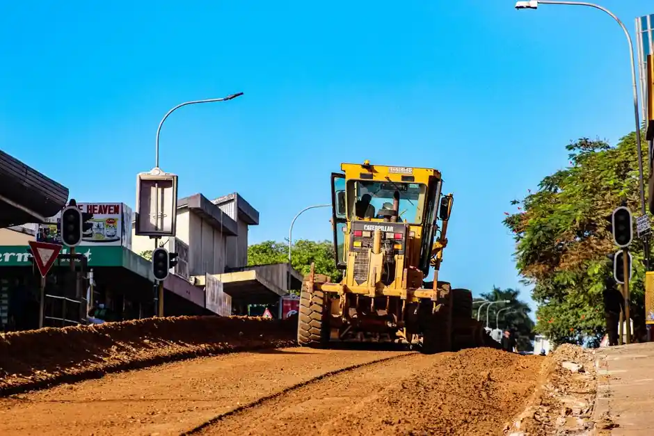
A stepper motor is a synchronous electric drive that rotates in fixed increments of 0.9 to 1.8 mechanical degrees per pulse, delivering open-loop positioning without an encoder [S2]. A motor grader, by contrast, is a self-propelled heavy machine with a long moldboard, a mid-mounted blade, and a multi-axle chassis, typically weighing 11 to 25 tonnes and powered by a 100 to 250 kW diesel driving hydrostatic or mechanical-driven wheels. The two products sit in completely different spec categories, so a head-to-head torque comparison would be meaningless.
What an engineer actually does is run two separate selection workflows: pick a stepper motor family and stepper drive topology for a motion axis, and pick a grader size class based on road geometry, haul-road speed, and material density. Both decisions are duty-cycle driven, but the metric that anchors each is completely different: stepper selection anchors on holding torque at standstill and incremental accuracy, while grader selection anchors on moldboard downforce, articulation angle, and frame articulation. Cross-comparing them is a category error.
Stepper Motor Selection Criteria: Torque, Speed, Open-Loop vs Closed-Loop
A stepper motor provides high holding torque at standstill and at low rpm, but torque drops as speed rises due to back-EMF losses inside the windings [S3]. A standard 1.8-degree hybrid stepper therefore performs best below roughly 1,000 rpm; above that range, output torque can fall by 30 to 50 percent depending on the driver voltage and inductance. Engineers who need high speed with flat torque should compare a stepper against a brushless servo, which uses a three-phase stator, a permanent-magnet rotor, and an encoder or resolver in closed loop [S3].
For stepper systems the open-loop simplicity is a real cost advantage: the same axis that needs a stepper plus stepper drive needs no encoder feedback in the basic topology [S3]. When the load is predictable, such as a belt-driven linear stage or a valve actuator, this keeps the bill of materials low. When the load varies unpredictably, such as a pick-and-place arm with shifting part masses, the stepper can lose steps without knowing it, since there is no position feedback in the open-loop configuration [S2].
Stepper Motor Lifetime, Driver Cost, and Operating Limits
A stepper motor that is not run past its rated torque and is properly sized for its load can reach roughly 10,000 hours of useful life, which equals about 1.14 years of continuous operation, or close to five years on a single-shift duty cycle [S1]. Bearings and winding insulation set that ceiling, not the commutation electronics. Running a stepper into resonance or stalling it under high inertial load shortens bearing life well before the windings fail, which is why pulse-rate profiling during acceleration matters as much as the rated torque figure.
Stepper drivers are more expensive than brushed DC motor drivers at the same current rating because the stepper drive needs more power FETs and additional logic to produce the multi-phase commutation sequence [S4]. A typical NEMA 23 or NEMA 34 bipolar stepper at 2 to 4 A RMS phase current uses an H-bridge per phase, plus current chopping at 20 to 60 kHz, which is the real cost driver. Compared to a brushless servo drive, however, the stepper drive still wins on parts count when the application is truly open-loop.
Motor Grader Selection Criteria: Weight Class, Moldboard, and Articulation
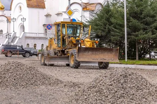
A motor grader is selected by total operating weight, moldboard width, and frame articulation range, not by motor type in the electrical sense. Light graders in the 11 to 13 tonne class carry a 3.0 to 3.7 m moldboard and suit road shoulder work and finish grading on subdivision streets. Mid-range 16 to 19 tonne graders carry a 3.7 to 4.3 m blade and handle highway maintenance, snow removal, and quarry haul-road grading. Heavy 20 to 25 tonne graders with 4.3 to 4.9 m blades handle mining haul roads and airport runway sub-base work. Choosing the wrong class for the haul-road speed or material density is the most common spec error on a grader purchase. [S2]
Articulation angle, typically 25 degrees to the left and right on most production graders, lets the front wheels pivot relative to the rear frame so the blade can stay in the cut while the machine crab-steers around obstacles. Tandem-drive rear axles with full-length frames give the tractive effort needed to hold the blade in a hard cut; without enough weight on the front axle, the wheels spin before the blade penetrates. For an ac motor or hydraulic motor drive inside the machine's accessory systems, the same sizing logic used in any industrial prime mover applies.
Comparison Matrix: Stepper Drive vs Brushless Servo Drive
The real comparison most engineers want is not stepper versus grader, but stepper versus brushless servo on a motion axis. Holding torque at low rpm: stepper wins, with full detent torque at standstill without a brake [S2]. High-speed torque: servo wins, since the closed-loop controller adjusts current per load to keep torque flat above 2,000 to 3,000 rpm [S3]. Position feedback: stepper runs without it, servo requires an encoder or resolver, adding cost and wiring [S3].
Energy efficiency: servo wins, because the stepper draws full holding current at standstill regardless of the actual load, while the servo only draws what torque the load demands [S2]. System cost: stepper wins on simple axes, since the drive, motor, and cabling add up to less than a servo system with feedback, brake, and matched drive. Maintenance: brushless servo is essentially maintenance-free over a similar service life; the stepper bearing is the wear item. Tuning: stepper is plug-and-play, servo needs inertia matching and gain tuning on first install [S3].
When to Use a Stepper, When to Use a Servo, and What Grader Has to Do With It
Use a stepper for low-to-mid speed open-loop positioning, indexing tables, small CNC axes under 1,000 rpm, valve actuators, and label dispensers where cost and simplicity dominate. Use a brushless servo for high-speed packaging, robotic arms, machine-tool spindles, and any axis where lost steps would scrap product or damage tooling. Do not use a stepper where the load can swing by more than 30 percent unpredictably, where dwell time at standstill is long and energy matters, or where micro-step resonance is going to cause audible noise and vibration. [S2]
None of that has anything to do with a motor grader, which is heavy equipment for shaping road surfaces and haul roads. The grader selection is driven by moldboard width, operating weight, and articulation, while the stepper motor selection is driven by holding torque, step angle, and driver topology. Engineers browsing both terms are likely either writing a spec list for a fabrication shop that also runs a small road-building fleet, or comparing cost-of-ownership between a precision automation line and a civil works project. Treat them as parallel decisions: pick the motor grader class by haul-road geometry, and pick the stepper axis by torque and speed envelope. A useful related spec map for the heavy-equipment side of that decision is the bulldozer vs motor grader stage-based selection guide.
Limits, Failure Modes, and Sourcing Notes
Stepper failure modes: lost steps during acceleration above the pull-out curve, resonance in the 100 to 300 rpm band, and bearing wear at the front shaft seal if the housing IP rating does not match the environment. Adding a closed-loop stepper with an encoder can recover lost-step detection, but the cost starts to converge with a small brushless servo. Driver sourcing: Texas Instruments, Allegro, and Trinamic supply most of the integrated stepper driver ICs in the 1 to 10 A RMS class; field-proven part numbers include DRV8462, DRV8889-Q1, and DRV8434S [S4].
Motor grader failure modes: moldboard wear on abrasive aggregate, circle-and-bolt slop after 5,000 hours without re-shimming, and hydraulic leak paths in the blade side-shift cylinder. Sourcing channels are OEM dealer networks and the used-equipment auction market, where 5,000 to 8,000 hour units typically sell at 40 to 60 percent of new list. The next spec decision downstream of either purchase is matching the prime mover rating to the duty cycle, which means reviewing the rated engine power curve against the expected average load factor. For sites that also need compaction gear, the road roller types and classifications spec map lines up the matching machines by task.