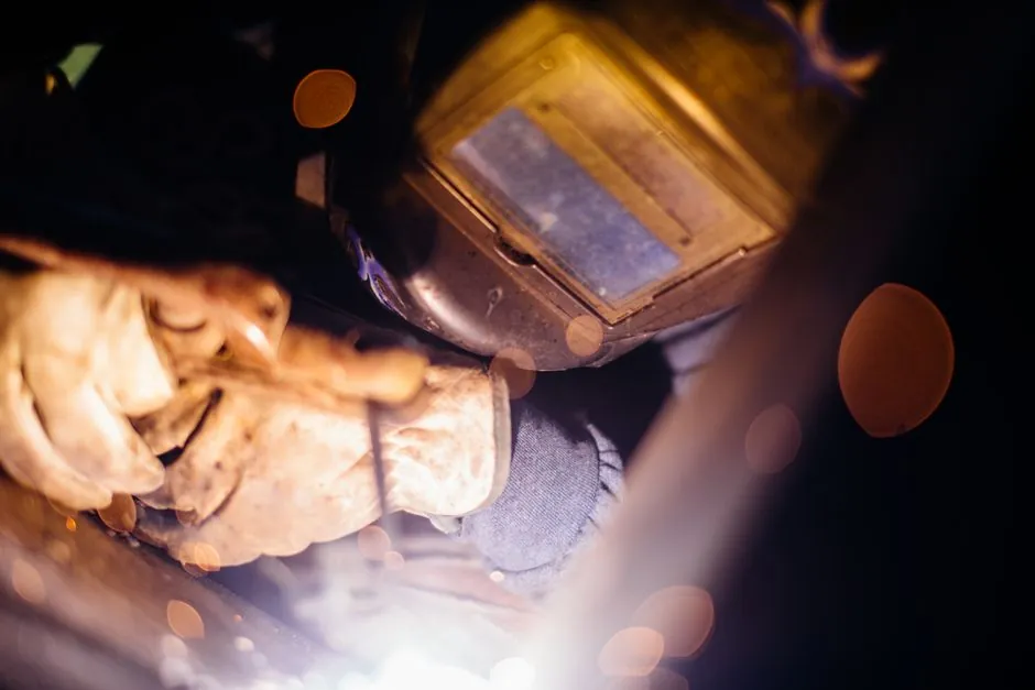
Drawn-arc stud welders are the default power source for tunnel segment, rebar anchorage, and composite concrete-lining work, because the process delivers deep fusion on structural plate while keeping heat input low enough to preserve the substrate's ductility [S2][S3].
Capacitor discharge (CD) units remain a secondary option only for thin-gauge or temporary tunnel fixtures; for the load-bearing headed concrete anchors and shear connector studs that carry the structural action in segmental ring construction, drawn-arc stays the workhorse, with typical stud diameters of 1/2, 5/8, 3/4, and 7/8 in dominating tunnel schedules [S2].
Tunnel-Specific Use Cases: Anchors, Shear Connectors, Conduits
Tunnel construction pulls on four distinct stud-welding applications: anchoring temporary ground-support plates, welding headed concrete anchors into segment rebar cages, installing shear connectors for composite steel-concrete invert and final lining transitions, and fixing guardrails, cable trays, and underground conduits [S2].
For segmental lining rings, headed concrete anchors transfer tension, shear, and combined loads from the steel reinforcement cage to the concrete; the welded head eliminates the need to drill, tap, or back-grout, which matters in a confined heading where drilling adds cycle time and dust [S2].
Shear connector studs handle the steel-concrete interface on the final composite invert and on utility gallery walls. The shrinkage rule from the construction data: diameters 1/2 in and under shorten by roughly 1/8 in after welding, 5/8 in drops by about 3/16 in, 3/4–7/8 in drop by 3/16 in (about 3/8 in for thru-deck), and 1 in or larger drop by about 1/4 in; that length loss has to be baked into stud callouts before rebar is cut [S2].
Tunnel ducts, cable trays, and guardrail posts are lighter-duty work, often thinner steel sections, where a CD system or a smaller drawn-arc setup finishes hundreds of welds per shift with limited spatter and almost no post-weld grinding, which is the productivity argument that gets CD onto a tunnel job in the first place [S1][S2].
Drawn-Arc vs Capacitor Discharge: Process and Spec Differences
Drawn-arc stud welding completes a fusion bond comparable to or stronger than the base material by sustaining a controlled arc between stud and plate, collapsing the stud into the molten pool under spring or solenoid plunge, and finishing in roughly a second; CD stud welding instead discharges a bank of capacitors through the stud in milliseconds, with a much shallower heat-affected zone [S1][S2][S3].
For tunnel anchor work the heat input matters for two reasons: the substrate is often quenched-and-tempered rebar or heavy plate where hardness can climb, and the back of the section is frequently visible formwork or waterproofing membrane that cannot tolerate discoloration. Industry guidance puts the carbon-content ceiling at 0.18% to avoid post-weld embrittlement in mild-steel substrates; higher-carbon stock needs preheating or a different process choice [S3].
Markings on the back of the sheet are practically unavoidable when drawn-arc is used on stainless or aluminum under 4 mm, and on any steel under 1 mm an indentation always occurs; CD avoids most of that, which is why the CD unit gets a place on tunnel projects even when drawn-arc does the structural welds [S3]. A side-by-side view that fits a typical tunnel buying decision:
Process selection on a tunnel job reduces to four criteria: base-material thickness (under 1 mm = CD only; 1–4 mm = CD preferred for appearance; 4 mm+ = drawn-arc for fusion depth), stud diameter (under 1/2 in = CD or small drawn-arc; 1/2 in and up = drawn-arc), load requirement (decorative or tray-clip duty = CD; structural anchor or shear connector = drawn-arc), and access (overhead, inside rebar cage, single-side access = drawn-arc with long leads and ferrule; open bench on a precast yard = either, but CD wins on throughput on small studs) [S1][S2][S3].
Equipment Specs and Site Logistics for Tunnel Work
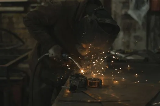
Tunnel headings punish heavy, mains-locked equipment. Portable drawn-arc units with long weld leads, lightweight guns, and ferrule support are the standard kit, and many sites carry a small CD welder alongside for thin-cable-tray or temporary-lighting brackets where spatter control and appearance matter more than fusion depth [S1].
Power and cooling sizing follows stud diameter. A 1/2 in headed concrete anchor draws a fraction of the current a 7/8 in shear connector does, so a single mid-range drawn-arc power source can run all anchor work while the larger studs need a heavier tap setting and longer preheat. For thru-deck or thick-plate applications the stud shortens more, so a longer stud must be ordered to compensate; the 3/8 in loss on a 3/4–7/8 in thru-deck stud is not optional [S2].
Material compatibility drives consumable choice. Standard drawn-arc ferrule and arc shields are designed for mild-steel stud-to-mild-steel base; stainless and aluminum combos need matched ferrules and shorter weld times to keep the heat-affected zone narrow [S1][S3].
Operator Qualification and Quality Control on Site
AWS D1.1 Chapter 7 sets the qualification cadence for stud welding on structural tunnel work: a stud-welder operator qualifies the process, the welder, and the equipment together, once per shift, and any change in lead length or machine forces a re-qualification. That is a daily check, not a one-time ticket, and the inspector is expected to witness a production-style test on the actual stud and base-metal combo in use that day [S4].
Two quality flags a process engineer should track on every shift: the bend or torque test result, and the stud-length after-weld measurement, which the spec data ties to stud diameter. If the after-weld length is short of the expected value for the diameter, plunge, current, or lift is wrong, and the joint is suspect before any NDT is run [S2][S4].
For the rare case of manual GMAW attachment of studs (a substitute for stud-gun work when the gun cannot reach), AWS D1.1 Section 4 Part C governs the welder qualification, with Table 4.10 setting the test geometry; a fillet-weld break test is normally accepted, and the flux tip on the stud must be removed before any GMAW attempt or the slag runs the test [S4].
Failure Modes and Common Tunnel-Job Mistakes
Three failure patterns dominate tunnel stud-welding rework: over-plunged studs (too much stud protrusion past the collet or ferrule) that throw molten metal and leave a porous root; under-plunged studs where the arc gap is too short to form a proper fusion zone, so the stud sits on top of the plate instead of being fused into it; and base-material hardening in higher-carbon plate or rebar that has not been preheated [S3].
Plunge setting is the most-cited parameter in the trade data: for drawn-arc it is the distance the stud protrudes from the ferrule, and for CD it is the distance the stud protrudes from the collet that retains it inside the gun. Either too little or too much protrusion produces a defective weld, and there is no automatic compensation; the gun setup has to be checked at every shift change [S3].
Worn collets are the silent killer. A tired collet changes the stud's lift geometry inside the gun and quietly degrades weld quality long before the arc timing looks off on the control box, which is why field maintenance of the gun, including the wearable collets, is treated as a primary quality control, not a shop-floor chore [S3].
Selection Checklist and Comparison Reference
A tunnel project engineer should pin four numbers before issuing a stud welder spec: stud diameter (1/2 to 7/8 in for most concrete-anchor and shear-connector work; up to 1 in for heavy composite inverts), base-material thickness (anything under 1 mm forces CD; 1 to 4 mm prefers CD on appearance grounds; above 4 mm and drawn-arc is the choice), carbon content of the base (cap at 0.18% to avoid embrittlement), and power-class on the welder (rated for the largest stud on the schedule plus a margin for thru-deck) [S1][S2][S3].
For a compact spec map inside a dense article, the four-way decision grid looks like this: structural anchor or shear connector in concrete (drawn-arc, ferrule, 1/2–7/8 in studs, daily D1.1 qualification), cable tray or guardrail (CD or small drawn-arc, sub-1/2 in studs, low spatter, no grinding), thin stainless or aluminum trim under 4 mm (CD to avoid back-side marking), and repair welds where a stud gun cannot reach (GMAW fillet weld, D1.1 Section 4 Part C, filler metal matched to stud) [S1][S2][S3][S4].
Cross-references for adjacent spec work on a tunnel job: the stud welder selection criteria reference lays out the process comparison in more detail, while the CD vs drawn-arc spec map for interior finishing covers the appearance-driven side of stud choice, and the drawn-arc vs CD concrete spec map extends the diameter and material rules to heavier rebar and composite work. The wider construction-equipment context lives in the construction machinery and equipment encyclopedia, with the stud welder encyclopedia entry as the process definition anchor.
Two trackable signals to watch on the next tunnel tender: the stud-diameter callout band (1/2 in and 5/8 in for segment anchors; 3/4 in and 7/8 in for invert shear connectors; verify the after-weld length loss is itemized so the rebar fitter is not guessing), and the qualification clause (D1.1 Chapter 7 daily stud-gun qualification, plus Section 4 Part C if any GMAW stud attachment is on the method statement). A third signal is gun-portability spec: a tunnel job that lists only a bench-top CD unit has likely underestimated the drawn-arc anchor scope.
Component reference pages worth checking: construction tools.