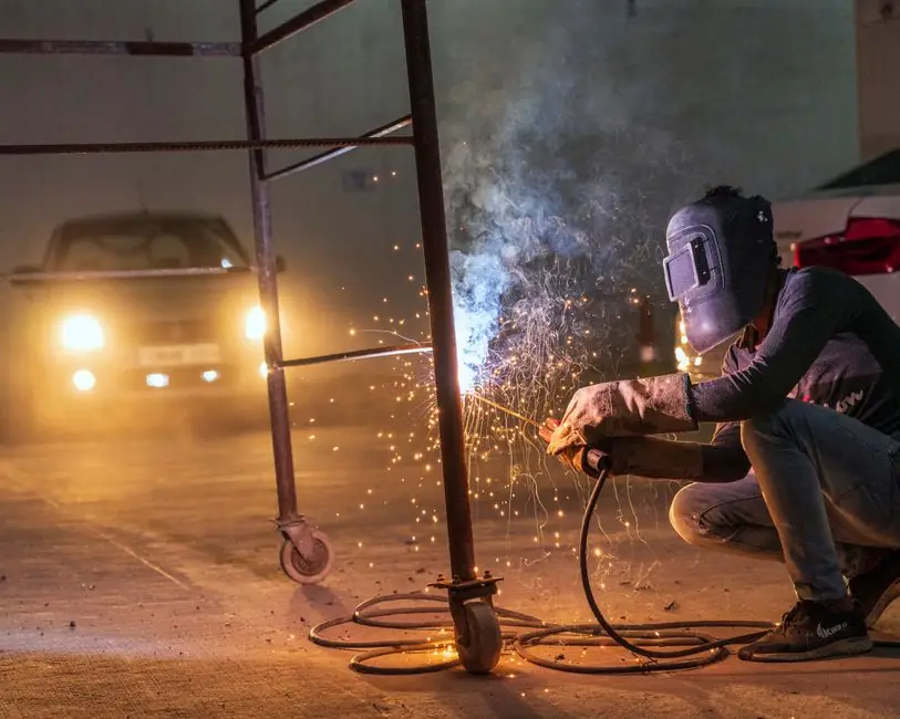
For HVAC installation, Capacitor Discharge (CD) stud welders dominate the duct, panel and lining trade, with typical M3–M8 stud capacity and 1–3 ms weld times that suit thin galvanised and stainless sheet without burning through the metal [S5].
The HVAC scope is fastener-heavy and load-light: duct hangers, insulation pins, thermostat brackets, panel clips and equipment-mount studs all run on small-diameter fasteners, so the selection question is rarely about raw penetration and almost always about sheet thickness, finish cleanliness and cycle time on site [S2][S5]. Working through a stud welder selection criteria map first prevents the two classic mistakes, over-spec'd Drawn Arc on 0.6 mm duct and under-spec'd CD on 6 mm structural bracketry.
CD vs Drawn Arc: which process actually fits HVAC
CD stud welding is the go-to for HVAC because the stud sits against a thin sheet, typically 0.5–3 mm galvanised steel or stainless, and a CD unit fires in 1–3 ms with low total heat input, leaving the cosmetic side of the duct unmarked [S5]. Drawn Arc (DA) is the heavier process, with deeper penetration, larger fillet, and typical stud range M6–M25+, so it shows up in HVAC only when the base metal thickens, such as unit frames, structural channels and rooftop-curb brackets [S2][S5]. For a deeper process-side comparison, the CD vs DA breakdown for concrete-style jobs translates cleanly to HVAC bracketry because the same M6+ stud size class is the decision boundary.
A quick rule that holds in practice: if the base metal is under 3 mm and the stud is M8 or smaller, choose CD; if the stud is M10 or larger, or the base is 4 mm and up, step up to Drawn Arc. Outside that envelope, stud welding equipment choices diverge fast, and field operators will feel the difference in lift-off, spatter and rework rate.
Stud size, base metal and current class: the matching math
Selection starts with three numbers: stud diameter, base metal thickness, and base metal type, and these three drive the power-source class [S3]. For HVAC-grade CD work, mild-steel studs from M3 to M8 on galvanised sheet from 0.6 mm up to roughly 2 mm are the common case, with the welder set to the stud diameter's lower current band to avoid burn-through [S5].
Material set matters as much as size: stud welding works on carbon steel, stainless steel, aluminium and brass provided the base is electrically conductive, and the same unit that runs M6 mild-steel studs will also handle stainless and aluminium with adjusted current and gas coverage [S2][S4]. Dissimilar-metal HVAC assemblies, like stainless studs on galvanised duct, are routinely welded in production, but the operator must follow the stud-maker's published current/time curve rather than guess [S4]. A pragmatic approach is to size the power source 20–30% above the stud maker's nominal kVA so voltage drop across long HVAC site leads does not push the welds under-spec.
Site-power, gun ergonomics and HVAC-specific workflow
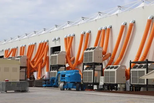
On HVAC sites, 110 V/240 V dual-voltage CD units are the practical pick because rooftop and mechanical-room power rarely matches a single fixed supply, and dual-voltage input lets the same machine run off temporary site feeds [S5]. Welding speed, measured in milliseconds per stud, is the headline productivity gain: an operator can lay several hundred CD studs per shift on duct-hanger prep, versus minutes per fastener for tapped or through-bolted alternatives [S2].
Gun choice is more than comfort: a lightweight CD gun with an adjustable gap setting lets one operator hold the stud perpendicular to the duct and fire without the arc blow common on curved or ribbed sheet, while a heavier DA gun with a foot-petri or auto-feed is mandatory once stud size passes M10 [S3][S5]. The wider system context, including how a stud welder fits next to other HVAC-installation tools like rotary hammers and power mixers, is mapped in the broader HVAC spec-criteria article, which uses the same site-power, weight and dust-class thinking. Earth-clamp placement is the single most overlooked item on HVAC sites; a poor clamp location adds resistance, drops current at the arc, and produces a chain of weak studs that all fail visual inspection.
Failure modes, acceptance tests and when to replace, not repair
The three recurring HVAC stud-weld failure modes are: burn-through on too-thin sheet (current too high, stud gap wrong), missing fillet (lift-off too early, usually on a worn CD gun spring), and reduced stud strength after galvanic reaction on stainless-on-galvanised pairs [S2][S4]. Acceptance is straightforward and should be enforced on every shift: a 90° bend test to destruction with the stud bending, not the weld, and a torque test against the stud-maker's published value, both of which are standard shop-floor checks for stud-welded fasteners [S3].
Do not try to field-repair a stud welder's control board or capacitor bank on a rooftop: send the unit back to the OEM or an authorised service centre, because the stored-energy CD bank in particular is a documented shock hazard even after the mains is disconnected. Replacement is the right call when arc firing becomes inconsistent across more than roughly 10% of cycles, when the gun's lift mechanism shows visible wear, or when the unit can no longer hold set voltage under load. For a fuller procurement-side view, the core spec and limits primer lists the diagnostic checks that should be on the commissioning sheet before the first duct hanger is fired. Selecting on stud size, sheet thickness and site power, then enforcing 90° bend and torque acceptance, is the path that keeps HVAC stud welding off the rework list.
Component reference pages worth checking: marine hvac, and arc welder.