
A Type 3 surge protective device conforming to EN 61643-11 — rated 10/20 kA on power lines, 5/10 kA on video lines, and 5/10 kA on control signal lines, with response times of 25 ns on power and 2 ns on video and control signal lines — is offered for CCTV surge protection by MOSEB Engineering [S2].
For an existing packaging line, the surge protection device (SPD) retrofit touches four subsystems: incoming LV power, branch feeders, data/control signal lines, and CCTV/IO remote segments; each layer has its own Uc, In, and Imax class, and a packaging engineer cannot pick one device to cover all four [S1].
EN 61643-11 Type Zoning and Where Each SPD Sits on the Line
EN 61643-11 defines Type 1 (service entrance, 10/350 µs lightning current waveform), Type 2 (sub-distribution, 8/20 µs), and Type 3 (equipment-level, 1.2/50 µs + 8/20 µs combined wave) — the Type number dictates the test waveform, not the joule rating alone [S2]. A packaging-line retrofit that reuses the existing MCC should keep Type 1+2 at the main LV board and add Type 3 at the machine, because Type 1 alone leaves 1.5 kV let-through under 8/20 µs stress that fails PLC and HMI insulation tests.
For greenfield cabinets the cascade is straightforward; for retrofits the engineer must measure the existing cable length between the upstream breaker and the load — a run over 10 m lets Type 2 alone deliver 2 kV clamping at the equipment, which usually exceeds the 1.5 kV IEC 61131-2 test level for PLC discrete inputs. Type 3 modules then trim the residual to under 1.0 kV. The data-line counterpart of OVR TC from ABB sits on the same DIN rail space and follows identical Type zoning but with Uc derated to 5–24 V DC per port class [S1].
Uc Voltage Matching: Picking Max Continuous Voltage Without Mis-Coordination
EN 61643-11 Uc (max continuous operating voltage) must equal or exceed the highest steady-state voltage the conductor can see including 10% LV tolerance and any DC offset — for 230 V nominal single-phase the practical Uc is 275 V AC; for 24 V DC control circuits it is 33 V DC minimum [S2]. Undersizing Uc causes thermal runaway and end-of-life short circuits inside the MOV; oversizing it raises the residual let-through voltage (Up) and defeats the protection.
On packaging conveyors and vacuum packaging machine feeders, the common failure is specifying a 275 V AC module on a 24 V DC encoder supply because the part number was already in the bin. Data-line SPDs like OVR TC carry Uc values as low as 5 V DC for RS-485 and 24 V DC for analogue 4-20 mA loops; the ABB data-line range is built around telephonic and IT equipment port voltages rather than power, so the engineer's first step is reading the equipment port spec, not the SPD datasheet [S1]. A 24 V DC Type 3 SPD is rarely interchangeable with a 24 V DC data-line SPD even when both look identical on the BOM.
Discharge Current In/Imax: Matching 8/20 µs Capability to the Exposure

In (nominal discharge current) and Imax (max discharge current) at 8/20 µs are the two kA values that determine how many medium-level surges the SPD can shunt before reaching end-of-service; the typical 10/20 kA pair on power and 5/10 kA pair on signal and video lines reflects the 8/20 µs exposure that most indoor packaging plants face after the service entrance [S2]. For outdoor feeders, rooftop equipment, or lines entering from a metal-clad riser, the engineer should step up to 20/40 kA on power and 10/20 kA on signal to absorb the higher 10/350 µs component.
When the line includes VFDs, servo drives, or switch-mode power supplies — which almost every modern automatic molding line and case-packer does — the SPD must be co-ordinated with the drive's built-in EMC filter. Mounting a Type 2 SPD directly on the drive's input terminals without 5 m of cable separation can cause the drive's filter capacitors to ring with the SPD's MOV capacitance, raising HF noise above the EN 61800-3 limit. The mitigation is the 5 m lead rule, or a series inductor on the SPD branch.
Response Time, Insertion Loss, and Signal Integrity
Response time Ta of 25 ns on power and 2 ns on signal/video is the published worst-case for Type 3 modules tested to EN 61643-11 [S2]. For surge events in the 1-5 kV band, the residual voltage at the load depends more on lead inductance and TVS/MOV technology than on the datasheet Ta figure, so the engineer should plan 0.5 m max lead length between SPD and protected terminals.
Insertion loss below 0.4 dB is the threshold that lets a Type 3 SPD sit in-line on a CCTV video path or 100 Mbit Ethernet run without degrading the signal [S2]. Anything above 0.5 dB begins to lift the bit-error-rate on PoE+ links and dimmer video at night-mode IR illumination. The OVR TC data-line family from ABB is designed to keep insertion loss inside this band for telephonic and IT ports [S1], which makes it a more reliable fit for an existing SCADA uplink than a generic power-line SPD dropped across the data pair.
Environmental and Mechanical Constraints: Enclosure, Tu, and Connector Type
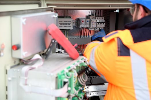
Tu operating range of -25 to +80 °C covers the standard packaging-floor ambient including CIP wash-down radiated heat peaks, but it does not cover cold-chain rooms below -25 °C or oven-side cable trays above 80 °C — for those, the engineer needs a derated or stainless-housed variant [S2]. The enclosure material drives corrosion class: aluminium alloy is acceptable for dry indoor MCC cubicles; for wash-down zones, stainless 304/316 with IP65+ rating is required.
Connector type — screw for power and control, BNC for video — should match the existing wiring method to avoid a secondary transition joint that itself becomes a surge inductance. On a retrofit, the cleanest method is to cut the existing BNC and re-terminate with an in-line BNC SPD; for power, the SPD mounts to DIN rail and the conductors land on screw terminals with ferruled ends. The aluminium-alloy housing class of TD2-06 / TD2-14 / TD2-15 is sized for indoor cabinet mounting, not for tray-side field deployment.
Comparison of Common Options Against Four Hard Criteria
Four realistic options for the power-side SPD slot: (a) Type 1+2 combined module at service entrance, 25 kA Imax, Uc 275 V AC, lead-mounted; (b) Type 2 sub-distribution module, 20/40 kA, Uc 275 V AC, DIN rail; (c) Type 3 equipment module, 10/20 kA, Uc 275 V AC, plug-in; (d) Type 3 data/signal module, 5/10 kA, Uc 5-24 V DC, DIN rail. Against the four criteria below, the trade-off looks like this: [S2]
- Surge capacity: Type 1+2 (a) wins (10/350 µs + 8/20 µs); Type 2 (b) and Type 3 (c) handle 8/20 µs only; data module (d) handles 5/10 kA on a few-volt port. - Let-through voltage Up at load: Type 3 (c) and data module (d) under 1.0 kV / under 50 V respectively; Type 2 (b) up to 1.5 kV. - Footprint and retrofit ease: Type 3 (c) and data module (d) plug into a single DIN slot, no breaker change; Type 1+2 (a) needs a dedicated breaker or fuse back-up. - Signal compatibility: only data module (d) keeps insertion loss under 0.4 dB for RS-485 / 4-20 mA / Ethernet; Type 3 power modules (c) are unsuitable on signal pairs because MOV capacitance loads the line.
What Should NOT Be Specified on a Packaging-Line Retrofit

A single Type 2 power SPD at the MCC and nothing at the machine is the most common under-spec seen in packaging retrofits, and it leaves the HMI and PLC exposed to the 8/20 µs residual. Conversely, putting a Type 1 SPD at the machine cabinet is over-spec — its 10/350 µs rating adds cost and let-through voltage without covering any additional threat that the upstream Type 1+2 has not already clipped. For data lines, a power-line Type 3 module used as a "universal" SPD on a 24 V DC encoder or RS-485 port will load the line with hundreds of pF of MOV capacitance, which is enough to break 1 Mbit Profibus and 100 Mbit Ethernet at the same time. [S1]
Sourcing, Standards, and Trackable Signals
The dominant 2026 sourcing channel for these modules in Asia/Europe is the distributor-plus-OEM channel — for example, MOSEB Engineering in Malaysia stocks PROMOV/TAIHANG Type 3 CCTV SPD TD2-06/14/15 with 15-day delivery [S2]. The relevant standards are EN 61643-11 for the SPD device itself, IEC 61131-2 for the PLC insulation test level the SPD must protect to, and EN 61800-3 for drive-side EMC co-ordination; the engineer should confirm each on the datasheet before purchase. ABB's data-line OVR TC range remains the reference low-voltage data SPD family on DIN rail [S1]. Two trackable signals for the next quarter: (1) the release of Type 1+2+3 combined DIN-rail modules for 690 V AC packaging-plant feeders, and (2) the convergence of SPD and surge protector PoE+ ratings for the growing number of vision-guided case-packers. For a related retrofit-side spec-map on drag-chain cabling that typically sits next to the SPD cabinet, see Drag Chain Cable Selection Criteria for Packaging Line Retrofit, and for the upstream power-distribution cabinet spec that the Type 1+2 module lands in, see Paint Booth Distribution Box: Spec-Map Selection Criteria.