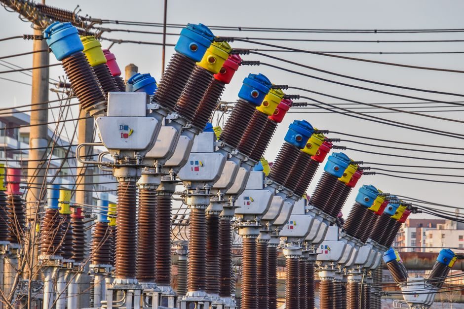
Voltage transformer (VT) selection in industrial and utility substations is governed by a single, non-negotiable rule: match the secondary core accuracy class to the load it feeds — a 0.2S metering core for revenue billing, a 3P protection core for fault detection [S2].
The same selection discipline applies to low-voltage line transformers feeding control panels, test rigs, and imported equipment: 115 V / 60 Hz and 230 V / 50 Hz are not interchangeable, and a transformer cannot shift line frequency [S3]. This article walks through substation-grade VT core classes, VT selection schemes for double busbar switchgear, and the lower-voltage line-transformer sourcing steps, with each decision node backed by a concrete number or class designation.
VT Core Accuracy Classes: 0.2S, 0.2, 0.5, 3P, 6P
Substation voltage transformers ship with multiple secondary windings, and each core carries an IEC-defined accuracy designation tied to its end use [S2]. A 0.2S metering core is specified for energy-accounting feeders where composite error over the 1–120% burden range must stay inside the class envelope, and the extended "S" band guarantees that low-load performance (1–5% of rated voltage) is metered at the same error bound as near-full-load.
Protection cores are labelled 3P or 6P, where the lower numeric class means tighter ratio and phase-error limits during the residual voltages that follow a fault on the primary system [S2]. For a 33 kV or 132 kV double busbar substation, the typical allocation is one 0.2S core per busbar for revenue metering, one 0.5/1.0 core for SCADA and indication, and one 3P core per feeder for distance and overcurrent relays. When synchro-check is required, the synchro-relay is fed by a dedicated 0.5-class core from each side of the breaker; mixing metering and protection on a single winding is a class violation and should be rejected at the enquiry stage.
Why a VT Selection Scheme Beats a Second VT Bank
In a double busbar MV switchgear, the line VT and busbar VT sit on opposite sides of the same circuit breaker, and only one of them is needed for a given breaker state [S2]. A VT selection scheme uses auxiliary contacts of the breaker and the bus coupler to route the active secondary voltage to the protection relay, synchro-check relay, and metering cubicle — eliminating the need for an additional VT per bay.
The economic case is hard to argue with: adding one redundant 33 kV VT per bay multiplies the busbar cost and the floor footprint, while a selection scheme adds wiring, four-pole auxiliary contacts, and interlock logic at a fraction of the price [S2]. The key engineering checks for that scheme are auxiliary-contact reliability (use gold-plated or silver-alloy contacts rated for the panel's control DC, typically 110 V or 220 V DC), control-wire segregation from power cables, and system interlocking that prevents the relay from seeing two out-of-phase sources simultaneously. For substations with three incomers and two bus couplers, the logic table runs to 27 valid states; without a formal scheme, designers routinely over-spec the VT count by 30–50%.
Line Transformers vs Auto Transformers vs Isolation Units

Low-voltage line transformers are a separate selection problem from substation VTs, and the decision tree starts with two fixed inputs: the available mains voltage and frequency at the wall socket, and the equipment's rated voltage and frequency [S3]. A Hammond-published compatibility chart maps 115 V / 60 Hz, 115 V / 50 Hz, 230 V / 50 Hz, and 230 V / 60 Hz against the equipment, returning one of three answers: step-up, step-down, straight isolation, or — in some cases — "will not work" [S3].
That "will not work" answer is a frequency-mismatch trap: a transformer changes voltage but never frequency, so 115 V / 50 Hz equipment cannot be powered from a 115 V / 60 Hz source by re-tapping alone [S3]. The second fork is isolation versus autotransformer: an isolation (double-wound) transformer has separate primary and secondary windings, giving galvanic isolation at roughly double the weight and cost; an autotransformer is a single-winding unit, half the weight and cheaper, but offers no isolation and is only acceptable when no ground-loop or fault-isolation requirement exists [S3].
For an equipment class, electronics containing ICs, transistors, or switch-mode power supplies (computers, instrument chargers, shavers, camcorder rechargers) must use an isolation transformer regardless of the step direction; purely resistive loads (heaters, hair dryers, electric blankets) can be served by an autotransformer [S3]. This rule aligns with the broader dry-type transformer design philosophy of physically separating primary and secondary for safety, and it is the same isolation principle that drives the spec sheets for power transformer units in industrial control rooms.
Selection Criteria Comparison: 4 Line-Transformer Options
Specifying the wrong line-transformer class costs both money and time, so the following four-way comparison anchors the decision to four concrete data points: voltage direction, isolation class, typical weight factor, and electronic-load compatibility [S3].
Step-down isolation transformer (Hammond series 172, 179, 289): accepts 230 V mains down to 115 V equipment; full galvanic isolation; weight roughly 1.0× baseline; suitable for electronic loads. Step-up isolation transformer (series 298): 115 V mains up to 230 V equipment; full isolation; same 1.0× weight factor; suitable for electronics. Straight isolation transformer (series 169, 171): same-voltage equipment on same-voltage mains; no voltage conversion, isolation only; weight 1.0×; required for electronic gear in mixed-ground environments. Autotransformer (series 170, 170E, 175): single-winding, no isolation; weight roughly 0.5× and 50–60% of the price of an isolation unit; restricted to simple electrical (resistive) loads such as heating elements [S3].
Who should NOT pick the autotransformer: any application feeding a PLC, a lab instrument, a medical device, or anything with a switching power supply — the lack of primary-to-secondary isolation exposes the logic ground to mains transients. For these loads, the isolation transformer is mandatory, and the isolation transformer selection guide covers kVA, dielectric withstand, and isolation-class sizing. Sites that need a full spec walk on the upstream distribution side — breaker sizing, busbar ratings, cabinet ingress — can cross-reference the distribution cabinet vs dry-type transformer selection map for the panel-level picture.
Primary-Side Rating, Burden, and Frequency Verification
Three checks prevent the majority of VT and line-transformer misorders. First, rated frequency: a 50 Hz CT or VT is allowed to operate on a 60 Hz network at the same accuracy class, but the reverse — a 60 Hz unit on a 50 Hz network — is not guaranteed and must be called out at enquiry [S5]. For a line transformer, the same rule appears in the compatibility chart: any row containing a 50 Hz equipment rating paired with a 60 Hz source is marked "will not work" [S3].
Second, burden: each protection and metering core has a VA burden limit, and exceeding it pushes the ratio error outside the class envelope. Burden is computed at the planned cable loop resistance plus relay impedance, and for 0.2S cores the burden is typically held below 10 VA to keep the 1–5% voltage range within the extended accuracy band. Third, primary voltage class: the VT's rated primary voltage must equal or exceed the system's maximum operating voltage (typically 110% of nominal for HV equipment, with BIL/kV-peak verified for the installation altitude). Skipping any one of these three checks is the most common cause of failed FAT or SAT witnessed during commissioning.
Who Should Skip a VT Selection Scheme
A VT selection scheme is not always the right call. Single busbar single-breaker substations, radial feeders without synchro-check, and installations where the additional auxiliary contacts and interlock wiring are impractical (e.g., retrofit jobs with limited panel space) are better served by installing dedicated VTs on both sides of the breaker [S2]. The cost trade-off flips when the busbar is double, when synchro-check is mandated by the grid code, or when the protection philosophy calls for two independent secondary sources for redundancy — in those three cases the selection scheme is the lower-cost, lower-footprint answer.
For the broader power-system spec walk, including kVA sizing, impedance, and BIL coordination on the upstream power transformer, the power transformer selection guide provides a parallel criteria framework. If the upstream protection scheme calls for a high-voltage tester on the secondary side for commissioning and periodic re-test, that belongs in the FAT plan rather than the transformer order — but flag it in the enquiry so the manufacturer's test report can record the dielectric test voltage the unit was built to withstand.
Trackable signals for the next sourcing cycle: a 50 Hz-only VT or line transformer must never be accepted for a 60 Hz application without a written derating note from the OEM; burden calculations on every 0.2S core should be filed with the enquiry so the manufacturer can pre-load the correct secondary winding resistance; and any autotransformer order on a panel that includes PLCs, drives, or instruments should trigger an automatic spec rejection and a re-quote as an isolation unit.