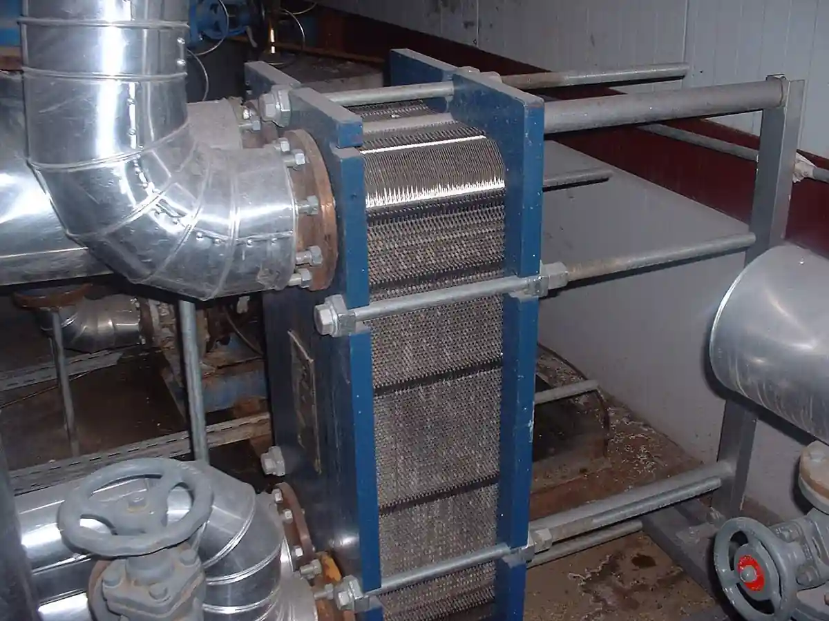
An air-cooled condenser, ACC, condenses steam turbine exhaust directly in finned tube bundles cooled by ambient air, replacing the cooling water circuit of a surface condenser plant with fans and extended surface and letting power and process plants site where water is scarce, expensive, or regulated away. The working geometry is the A-frame or roof type bundle: rows of large finned tubes sloped at 45 to 60 degrees forming an A above a steam distribution manifold, with axial fans below or above forcing or inducing air through the bundle faces. Design steam side vacuums run from roughly 8 to 30 kilopascals absolute depending on climate and economics, each kilopascal of back pressure worth real turbine output, and the machine is bought as a system of bundles, steam duct, condensate and non condensable removal, fans with their vfd control, and the wind and winter protections the site imposes.
Procurement engineers meet these machines on combined cycle and combustion turbine plants in arid regions, on thermal and biomass plants, on geothermal and waste to energy duty where plume and water arguments both land, and on process steam turbine exhausts in refineries and chemical plants. The decision this page settles is which arrangement and thermal basis fit the site: A-frame against other bundle layouts, forced against induced draft, the design dry bulb and wind basis with its availability accounting, fan power and noise against plot area, and the freeze protection the winter asks. The answer lands as an RFQ line set, exhaust flow and enthalpy, design conditions, back pressure guarantee, fan and VFD scope, and materials, and every chapter below feeds that line set so the ACC holds its vacuum through the summer afternoon that pays for it.
This page treats the air-cooled condenser as a purchasing object: how A-frame bundles condense steam against ambient air, what design dry bulb and wind assumptions cost in output and availability, how the steam side pressure drop and non condensable removal set the vacuum, what fan, VFD, and winter scope the machine carries, and how the whole decision folds into a defensible RFQ. It is written for engineers who issue specifications on dry cooling equipment, not for readers who want a brochure summary.
Chapter 1 / 06
What an Air-Cooled Condenser Is and What Is Being Decided
The defining act of the machine is condensing steam against ambient air with no cooling water loop, and the engineering is all surface and vacuum. Steam from the turbine exhaust duct enters a distribution manifold above the bundles, flows down the finned tubes condensing on the inner wall, air driven by axial fans flows across the fins, and the heat leaves as warmed air instead of warmed water. Because the condensing side runs under vacuum, every resistance matters: steam duct pressure drop, manifold distribution, tube side non condensable blanketing, and condensate drainage all add directly to turbine back pressure, and the design is a hydraulic and thermal balancing act that the chapter 2 arithmetic makes concrete. The machine is large because air is a poor heat transfer fluid, a utility ACC covers a plot the size of its turbine hall, and it is bought as an island of bundles, duct, fans, vacuum equipment, and controls.
What is being decided in this purchase is five commitments at once. First an arrangement: A-frame bundles with forced draft fans below, induced draft fans above, or the flat V and rectangular layouts that fit special plots, because draft choice changes wind response, fan power, and winter behavior. Second a thermal basis: design dry bulb temperature with its exceedance probability, altitude, and the back pressure guarantee at that condition, the single line that prices the turbine output. Third a steam side scope: duct sizing, distribution manifold, bundle tube count and fin geometry, the dephlegmator or secondary condensing sections that manage non condensables, and the vacuum system that removes them, a steam ejector or liquid ring machine train. Fourth a fan and control scope: fan count and diameter, vfd or two speed or fixed, the control philosophy against ambient and load, and the noise envelope the site and neighbors impose. Fifth a protection scope: wind walls and walkways, and the winterization, recirculation, bypass, or section isolation that keeps condensate from freezing at low load. A quotation that leaves any of the five to later detail is a plot drawing, not a machine.
Against its neighbors the ACC occupies precise ground in the condenser house. The surface condenser page covers the water cooled shell and tube machine this one replaces, and it already contrasts ACCs in its own selection discussion, while remaining the water cooled authority. The dry cooler page is the process fluid cooler, a sensible heat machine with no condensing steam and no vacuum, closer kin in finned bundle hardware but different physics. The air-cooled heat exchanger page is the process fluid ACHX family, coolers and condensers of process streams at pressure, not turbine exhaust under vacuum. The cooling tower page owns the evaporative water route that competes with dry cooling on water and plume grounds, and the evaporative condenser page covers the spray assisted middle ground. This page is the steam turbine exhaust ACC authority, and naming the neighbors keeps vendors quoting the right machine.
Standards and references frame the datasheet. ACC practice draws on the air cooled heat exchanger construction tradition, with bundle fabrication and fan testing per the air cooled equipment industry standards, and on the power plant vacuum system practice for ejector and liquid ring trains, with HEI surface condenser style vocabulary for vacuum and air removal borrowed where it helps. Structural design follows the wind and seismic codes of the site, and the noise envelope follows the local regulation and the neighbor's lawyer. Performance accounting follows the turbine and condenser acceptance tradition, back pressure at stated ambient and load with measured methods. A datasheet that quotes a back pressure with no design dry bulb and no exceedance basis is a price tag, not a specification.
The station around the ACC deserves naming in the RFQ too. The turbine exhaust duct delivers steam, sized for low pressure drop and often a flexible or bellows expansion joint at the interface. Condensate leaves by gravity and pump, hotwell and condensate return or boiler feed pump scope on the cycle, with the condensate dissolved oxygen target in hand because ACC condensate picks up air on its way through the vacuum. The vacuum system, steam ejector stages or a liquid ring vacuum pump train with its seal water, removes air and non condensables from the bundle headers. Fans carry motors with vfd or two speed control and their acoustic treatment, the fan deck carries its structure and walkways, and instrumentation reads the story, back pressure transmitter, ambient temperature, fan status, and condensate temperature, feeding the control that chases ambient with fan speed. Buying the bundles without the island is how startup arguments start.
Chapter 2 / 06
How the Machine Holds Its Vacuum
Back pressure is the product the ACC sells, and it is written by four resistances. The approach temperature, the temperature difference between condensing steam and entering air, sets the thermal floor, commonly 15 to 30 kelvin by economics: tighter approach means more bundle area and more fans, and the optimum moves with power price and plot cost. Air side performance writes the next line, fin geometry, face velocity, and fan performance against the system curve, with each fan's operating point set by bundle resistance and the deck's flow path. Steam side pressure drop writes the third, duct and manifold and tube entrance losses added directly to turbine exhaust pressure, which is why steam ducts are huge and manifolds divide carefully. Non condensables write the fourth, air leaking in and blanketing tube surfaces kills heat transfer locally and raises the condensing temperature needed, and the vacuum system exists to strip them from the cold end of the bundles before they accumulate.
The bundle does the condensing, and its geometry is a purchase decision in fin form. Air side area dominates, so tubes carry aluminum fins, helically wound L foot or embedded or extruded, on carbon steel tubes for the common utility ranges, with fin density commonly 8 to 11 fins per inch trading surface against fouling and pressure drop. Steam condenses inside the tubes with a high coefficient when the tube drains and vents correctly, and the bundle design manages two flows besides steam, condensate running down the tube wall and non condensables migrating toward the outlet end, which is why A-frame bundles slope steeply and why the last tube rows or a separate dephlegmator section do the final condensing with the air concentrated there for extraction. Tube materials run carbon steel with stainless options for aggressive chemistry, geothermal and some process duty pushing the whole selection up the alloy ladder.
Draft arrangement changes the physics the fans see. Forced draft, fans below the bundles pushing air up through the A, is the common utility form: fans sit in cooler air at the deck base, access is simple, and the bundle exit faces up where hot air rises away, but the discharge plume sits high and the arrangement can recirculate hot air in crosswinds without wind walls. Induced draft, fans above pulling air through, puts fans in hot air with derated density, higher power per unit flow, but holds a more uniform face velocity across the bundles and tolerates wind better in some layouts. The choice is argued per site with wind data and model studies, and the honest RFQ demands the recirculation and wind response basis, because the summer crosswind that lifts back pressure ten percent is a contract question when it is in the guarantee and a change order when it is not.
Wind is the ACC's weather, and the specification treats it as data. Crosswinds distort the flow through the fan deck, hot plume recirculation returns warmed air to the intakes, and high winds can stall fan performance outright, so the design basis states the wind speed and direction statistics with the thermal case, and wind walls, deep fan decks, and deck geometry answer it. Availability accounting belongs in the same paragraph: a design dry bulb with one percent annual exceedance buys back pressure performance at nearly all hours, while a tighter basis spends bundle area on the last hot hours, and the guarantee states which hours it covers. Sites that buy on annual average temperature and then discover afternoon derates have bought the wrong number cheaply.
Winter is the season that breaks ACCs, and the protection scope is a purchase line, not an option list. At low load and low ambient, steam flow through a bundle can fall until condensate freezes in the last rows, plugging tubes and bursting them by ice, so machines carry winter provisions, fan speed reduction and section isolation, recirculation ducts that warm intake air, reversing fans in some designs, steam bypass and sparge arrangements, and a control philosophy that trades vacuum willingly for safety at cold low load. The freeze protection logic is interlocked and tested, because the repair for a frozen bundle is tubes, outage time, and a story the buyer tells for years. The RFQ states the minimum load and minimum ambient the machine must ride, and the vendor answers with the hardware that makes it true.
Chapter 3 / 06
Arrangements, Bundles, and Duty Boundaries
The catalog reads in arrangements. The A-frame with forced draft is the utility standard, modules of two bundle slopes forming the A, steam manifold at the apex, condensate and vent headers at the bases, one or two axial fans per cell below, cells repeated to the required area. The induced draft A puts fans above the apex, fewer and larger, with the flow uniformity and wind tolerance arguments noted in chapter 2. Flat V and rectangular layouts arrange bundles at shallower angles or flat with vertical fans, for plots and process duty where the A does not fit, trading the steep drainage that helps A-frames in vacuum for layout freedom. Once through versus recirculating steam side layouts, and the dephlegmator or parallel condensing sections that concentrate non condensables, are steam side architecture choices the vendor engineers per vacuum system selection.
Cell and fan scope is the modularity the buyer scales. A utility ACC is a street of cells, each an A module with its fans, dampers where fitted, structure, and its piece of the manifold, and the count comes from the area calculation at design conditions with the redundancy philosophy the availability target wants, cells isolatable for maintenance at partial load. Fan diameter runs 6 to 12 meters class by vendor, with motor, gearbox or direct drive, and the vfd count against fixed speed cells is an economics line, vfd on every fan buys control resolution and winter turndown, vfd on part of the deck with staged fixed cells trades that back. Dampers and section isolation valves join the winter scope on cold sites. The structure, fan deck, walkways, and wind walls, is structural engineering with wind loads, and its scope is bought with the machine because the plume and recirculation physics live in it.
Boundaries are worth stating bluntly. This page is the steam turbine exhaust ACC authority, and it does not double its neighbors: the surface condenser page owns water cooled condensing with its circulating water and cooling tower train, the dry cooler page owns process fluid sensible cooling, the air-cooled heat exchanger page owns process fluid coolers and condensers at pressure, the cooling tower page owns evaporative heat rejection, and the evaporative condenser page owns the spray assisted condensing middle ground. A process condenser vacuum duty on a refinery vacuum system shares physics but is bought on the process pages. The selection chapter sends each duty to its machine, because the four neighbors quote against each other badly when the RFQ blurs them. The map below compresses the boundaries into one table.
Arrangement
Fan and layout
Best duty
Watch out for
A-frame, forced draft
Axial fans below, cells repeated
Utility ACC standard, simple access, cool fan air
Crosswind recirculation without walls, plume at deck
A-frame, induced draft
Fans above the bundles
Uniform face velocity, wind tolerance cases
Fan power in hot air, access at height
Flat V or rectangular
Shallow or flat bundles, vertical fans
Process plots and low profiles
Drainage and venting geometry at vacuum
With dephlegmator sections
Secondary condensing for non condensables
Large machines, tight vacuum targets
Vacuum system sizing couples to section design
Cold site winterized
Recirculation, isolation, reversing provisions
Subzero ambient duty
Freeze logic interlocks and minimum load basis
Heller type indirect dry cooling
Dry tower with surface condenser cycle
Water free sites wanting the Heller architecture
Different machine, bought on its own cycle basis
Chapter 4 / 06
Key Specification Parameters
The table below decodes the datasheet lines that decide whether a quoted ACC holds its vacuum at the hours that pay. Each row is a purchase defining parameter; the paragraphs after the table explain what to demand and what a weak answer looks like.
Attribute
Typical range or options
What it decides
Exhaust steam flow and enthalpy
Design and maximum with wetness basis
Bundle area, manifold and duct sizing, the whole duty
Guaranteed back pressure
8 to 30 kPa absolute by climate and economics
Turbine output at the guarantee conditions
Design dry bulb and exceedance
1 or 2 percent annual exceedance common
The hours the guarantee covers and the area bought
Wind basis
Speed and direction statistics with thermal case
Recirculation and derate risk, wind wall scope
Approach temperature
15 to 30 K by economics
Bundle area and fan power against capital
Bundle geometry
A-frame slope, tube and fin specification
Area per cell, drainage, fouling, and materials
Draft and fan scope
Forced or induced; count, diameter, vfd or fixed
Fan power, control resolution, noise, winter turndown
Vacuum system
Steam ejector or liquid ring train with capacity
Non condensable removal and vacuum at all loads
Noise envelope
dBA at boundary per regulation
Fan speed limits, acoustic treatment, cell count
Winter provisions
Minimum load and ambient with protection scope
Freeze safety interlocks and isolation hardware
The back pressure and design condition rows are the contract in two lines, and they must travel together. Demand the guarantee at a stated dry bulb, exceedance basis, and load, with the measured test method named, and demand the degradation curves, back pressure against ambient across the operating band, because the plant lives on those curves rather than on the single guarantee point. Ask what wind condition the guarantee assumes and what the machine does at the site's actual crosswind statistics, and price the wind walls and deck depth that answer it. A back pressure quoted without its weather is a number, not a commitment.
The fan and vacuum rows set the operating cost and the vacuum floor. Fan power at design is a large motor list, tens of fans at the utility scale, and vfd scope decides how much of it runs at part ambient, so the RFQ prices fan energy at the site's ambient duration curve, not at design alone. The vacuum system capacity, air removal in kilograms per hour at the vacuum, belongs to the leak reality of the plant, and the condensate dissolved oxygen target ties to it, with deaeration on the cycle handled per the deaerator page. The second table compresses the site decision the way a specification meeting argues it.
The decision sequence is short enough to run as a specification meeting checklist, and each step eliminates a class of quotations before price comparisons begin.
State the cycle honestly: exhaust flow and enthalpy at design and maximum, the back pressure the turbine economics want, and the value of a kilopascal in output, because that number prices every other line.
Fix the site basis: design dry bulb with exceedance statistics, altitude, wind speed and direction data, and the noise boundary, as data in the RFQ, not as assumptions discovered later.
Choose the arrangement: A-frame forced or induced draft by plot and wind case, with the recirculation and wind response basis demanded from every bidder.
Set the thermal economics: approach and area against fan power, with the annual energy priced on the ambient duration curve and the back pressure degradation curves delivered.
Scope the steam side: duct sizing, manifold and bundle count, dephlegmator or section architecture, and the vacuum system capacity against the plant's leak and air basis.
Scope the fans and control: count, diameter, vfd versus staged fixed, noise treatment, and the control philosophy across ambient and load.
Fix the winter basis: minimum load and minimum ambient with the protection hardware and interlock philosophy, demanded as a tested system.
Fix the verification evidence: back pressure test method at stated conditions, fan and vacuum performance data, structural wind basis, and the freeze logic test protocol.
Against neighboring equipment the comparison a specifier needs runs as follows, and it belongs here in the selection chapter rather than in the page title. A surface condenser with its cooling tower delivers lower back pressure where water exists and is bought on its own page. A dry cooler or air-cooled heat exchanger serves process fluids at pressure, sensible or condensing, without vacuum architecture. A cooling tower or evaporative condenser buys wet bulb performance at water and plume cost. The ACC takes the duty when water is the constraint or the plume is the argument, at the back pressure and fan power its climate imposes. Name the neighbors in the RFQ and every vendor quotes the same machine against the same afternoon.
The RFQ block should be written once and reused. A complete block reads: exhaust steam flow and enthalpy at design and maximum with wetness stated; required and guaranteed back pressure at named conditions; site data, design dry bulb with exceedance basis, altitude, wind statistics, noise boundary, and plot limits; arrangement proposed with cell and fan count and diameters; bundle specification with tube and fin materials and geometry; draft type with the wind and recirculation response basis; fan power at design and the vfd or staging scope with control philosophy; vacuum system type and capacity in air removal at the vacuum; condensate removal and dissolved oxygen interface; winter provisions with minimum load and ambient and interlock scope; structural and walkway scope with wind loads; instrumentation list including back pressure transmitter, ambient, and fan status; and the performance test method with degradation curves as deliverables. A quotation returned without the degradation curves or the wind basis is incomplete at any price.
Chapter 6 / 06
Installation, Standards, Failure Modes, and Maintenance
Installation quality decides whether the vacuum the design promised exists in steel. The exhaust duct goes in with its pressure drop held, expansion and supports per the pipe analysis, because every pascal there is turbine output. The manifold and bundle headers assemble with the slope and drainage the drawings show, and the condensate and vent lines prove their pitch, an ACC is a gravity machine on its liquid side. Fan decks, gearboxes, and motors align and lubricate per the rotating machine discipline, vfd loops commission against the control philosophy, and the wind walls and walkways complete before the performance test rather than after the first crosswind event. The vacuum system installs with its ejector or liquid ring train proved for capacity, and the whole island leak tests, held vacuum against time, before steam ever arrives, because hunting air leaks at load is the expensive way.
Commissioning proves the guarantee and the protections. The performance test runs at stated ambient and load with the agreed method, back pressure measured against the manifold with air removal proved, and the degradation curve checked at points across the ambient band, because the plant runs the curve, not the point. The fan deck proves its control, vfd response and staging against ambient and load, and the noise survey at the boundary closes the acoustic commitment. The winter protections test before the first freeze, isolation and recirculation proved in sequence, because the interlock that has never been exercised is a wish. The freeze season's first low load run is watched, condensate temperatures by cell, looking for the cold corner that warns before it bursts.
Failure modes in service follow a short and predictable list. Air in leakage raises back pressure gradually and then suddenly, found by vacuum system trend and fixed by leak hunting at flanges, gland, and instrument lines, and it is the most common ACC problem in the field. Non condensable accumulation, vacuum system capacity lost or sections unvented, blankets bundle area and mimics fouling, and the vent and dephlegmator architecture is the defense bought at design. Fan and gearbox failures follow the rotating machine statistics, bearing wear announcing in vibration, blade issues in acoustic signature, and the fan deck condition monitoring, a vibration sensor route, schedules them. Fin fouling, pollen, agricultural dust, and fly ash, raises air side resistance and back pressure seasonally, answered by washing with the access the deck provides. Freeze damage is the catastrophic mode, tubes split by ice at cold low load, prevented by the winter logic and its interlocks, and repaired by retubing bundles at outage cost. Structural issues, wind wall and deck fatigue at high wind sites, belong to the inspection calendar the wind loads imply.
Maintenance intervals scale with climate and duty more than with running hours. Fan and gearbox service follows the rotating machine calendar, lubrication routes and vibration trends, with gearbox oil analysis on the larger decks. Bundle washing goes on the seasonal schedule the fouling environment sets, and fin condition surveys, bent and missing fins from hail and work access, join it. The vacuum system gets its ejector nozzle and liquid ring service with the capacity test read against trend, and leak hunting becomes an instrumented habit after any outage that opened the vacuum. Instrumentation calibration, back pressure above all because turbine output is billed against it, follows the plant calendar. Every season produces numbers, back pressure against ambient by cell, fan energy, and wash effectiveness, and those numbers calibrate the next RFQ, which is how a purchasing file gets smarter instead of just older.
FAQ
What back pressure can an ACC actually guarantee?
Common design vacuums run from roughly 8 to 30 kilopascals absolute, set by climate and economics rather than by machinery limits: hot sites and cheap coal buy looser vacuums, cold sites and expensive fuel buy tighter ones with more bundle area. The guarantee is a weather contract, so demand it at a stated design dry bulb with an exceedance basis, plus the degradation curves across the ambient band, because the plant runs the curve.
Forced draft or induced draft fans?
Forced draft below the bundles is the utility standard, simple access and cool dense air at the fan, with wind wall and deck design managing crosswind recirculation. Induced draft above pulls a more uniform face velocity through the bundles and can suit wind exposed layouts, at the price of fans working in hot light air with more power per unit flow. Argue it per site with wind data, and put the wind response basis in the guarantee.
Why does wind change my back pressure?
Crosswinds distort flow through the fan deck and can push the hot discharge plume back into the intakes, recirculation that warms inlet air several degrees, and every degree of inlet air is back pressure. High winds can also stall fan performance directly. Wind walls, deep decks, and layout answer it, and the RFQ should carry the site wind statistics with the thermal case so the response is guaranteed rather than discovered.
How does an ACC handle freezing winters?
With hardware and interlocks bought for it: fan speed reduction and section isolation to keep steam velocity and condensate warmth up, recirculation or reversing provisions that warm intake air, and bypass or sparge arrangements at low load, all governed by a freeze protection logic that is tested before the first freeze. The RFQ states minimum load and minimum ambient, and the vendor answers with the system that makes the sentence true, because a frozen bundle is a retubing outage.
What removes air from the system?
The vacuum system, a steam ejector train or a liquid ring vacuum pump machine with its seal and condensing scope, extracting air and non condensables from the cold end of the bundles or a dephlegmator section where they concentrate. Its capacity in kilograms per hour of air at the design vacuum is sized to the plant's leak reality and proved by test, because accumulated air blankets tube surface and raises back pressure exactly like fouling.
How is ACC performance verified?
Back pressure at stated ambient and load, measured at the manifold with air removal proved and the method agreed in the contract, plus the degradation curves checked at points across the ambient band and the fan power read against the guarantee. Those curves and the noise survey at the boundary are the deliverables the plant lives with, and a bid without them is a single point masquerading as a machine.
When is an ACC the wrong choice?
When water is available and cheap, a surface condenser with a cooling tower buys lower back pressure at the wet bulb, and the wet route wins the output math. When the duty is a process fluid at pressure rather than turbine exhaust, the air-cooled heat exchanger and dry cooler pages own the machine. The ACC earns its plot when water is scarce, regulated, or plume contested, at the climate's back pressure and the fan power its air demands.