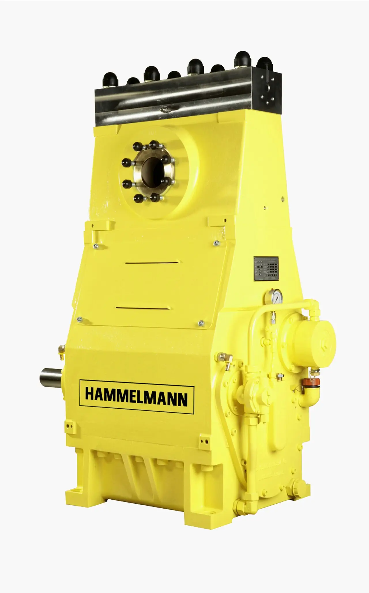
A diaphragm compressor is a reciprocating gas machine in which a crankshaft-driven hydraulic plunger pulses oil behind a sandwich of three thin metal diaphragms, and the diaphragms, not a piston, do the compressing. Process gas is drawn in and pushed out of a contoured cavity while it touches nothing but metal walls and two self-acting valves: no crankcase oil, no packing, no sliding seal in the gas path. Every joint the gas crosses is a static gasket or metal seal, which is why the family quotes external leak rates below about 1 x 10E-6 std cm3/s and why it owns the duty of compressing hydrogen, toxic, corrosive, and high purity gases that must not see lubricant or air. Heads run from modest pressures to the 300 to 700 bar family, with hydrogen filling specials to 450 bar and above, in frames from 15 to 400 kW.
Procurement engineers meet the metal diaphragm compressor, also sold as a membrane compressor, at hydrogen refueling and electrolyser sites, chlorine and fluorine plants, silane and specialty gas filling rooms, helium recovery loops, and pilot plants that need a small flow at a serious pressure without contaminating it. The decision this page settles is narrow and practical: whether the duty truly needs leak-tight compression or an oil-free alternative would do, how many stages and what discharge temperature the gas tolerates, what head integrity monitoring the package must carry, and which materials and hazardous-area evidence belong in the order. The answer lands as an RFQ line set: gas and purity, suction and discharge pressure, capacity, stages, leak detection method, wetted materials, area rating, cooling, and driver.
This page treats the metal diaphragm compressor as a purchasing object: the hydraulic drive and cavity geometry behind the leak-tight claim, the three-diaphragm sandwich and the integrity monitoring that watches it, stage and discharge temperature limits for gases as different as hydrogen and chlorine, package scope from bare frames to hydrogen filling skids, and how all of it is written into an RFQ. It is written for engineers who issue purchase specifications, not for readers who want a brochure summary.
Chapter 1 / 06
What a Diaphragm Compressor Is and What Is Being Decided
The defining hardware is the diaphragm head, and it is two machines in one. Below the head sits an ordinary slider-crank power end: crankshaft, connecting rod, crosshead, and a hydraulic plunger, the same architecture a high-pressure plunger pump uses. Above the head, the plunger works on a column of oil, and the oil column flexes a sandwich of three thin metal diaphragms, typically stainless 301 or 316L, with Inconel and Monel options by gas, each plate a few tenths of a millimeter thick. The process-side diaphragm bounds a shallow contoured gas cavity fitted with a suction and a discharge valve; as the diaphragm sweeps up and down with the oil pulse, the cavity inhales and exhales gas exactly as a piston cylinder would, but with no piston rings, no rod, and no packing anywhere in the gas path. Every seal the gas sees is static: gaskets and metal-to-metal joints torqued once and held.
What is actually being decided in this purchase is whether the gas is worth the leak-tight architecture, and what form of it to buy. Four commitments are made at once. First, the purity commitment: gas from a metal diaphragm machine meets oil-free specifications by construction rather than by filtration, and the buyer decides what leak-rate and integrity evidence must back that claim. Second, the pressure commitment: stage count sets the discharge pressure family, 300 to 700 bar in the established heads and higher in specials, and every stage decision carries a discharge temperature the diaphragms must survive. Third, the monitoring commitment: the head integrity system that detects a ruptured diaphragm and shuts the machine down is a purchase line, not a given, and its behavior on failure decides whether a hydrogen release is a shutdown or an event. Fourth, the package commitment: intercoolers, aftercoolers, gas detection, and motor area classification convert a bare frame into a station, and the scope boundary decides who supplies each. A quotation that answers only kilowatts and bar has skipped all four.
Two boundaries must be stated plainly because the name collides with neighbors. This page is the metal diaphragm gas compressor, the leak-tight branch of positive displacement gas compression; it is not the diaphragm pump, the air-operated double-diaphragm liquid machine that moves slurries and chemicals at low pressure, a completely different product with a shared word in its name. And this page does not replace the reciprocating compressor leaf, which covers the piston gas machine family as a whole; the diaphragm machine is that family's leak-tight subset, bought when the gas must be isolated rather than merely moved. Against the continuous machines, the screw compressor is the default plant air and process gas workhorse at flows the diaphragm frame cannot reach, and the centrifugal compressor owns high steady flows at moderate ratios; neither offers a static-sealed gas path. The metal diaphragm compressor takes the narrow territory where small flow, high pressure, and absolute gas isolation arrive together.
The duty list follows directly from that territory. Hydrogen: electrolyser offgas recompression, trailer unloading, and refueling precooling and dispensing packages, where the hydrogen diaphragm compressor holds purity for fuel cell feed and containment for a flammable gas. Halogens and corrosives: chlorine, fluorine, and hydrogen fluoride service with Monel or nickel wetted parts. Semiconductor and specialty gases: silane and related pyrophorics, where the compressor may draw from a gas cabinet and every wetted surface is a purity decision. Inert recovery: helium and argon loops where each percent of gas is too valuable to leak or contaminate. Add tank and pipeline testing, laboratory high-pressure sources, and nitrogen for purge and blanketing supply, and the family map is complete: capacities 0.5 to 300 Nm3/h family, per-head ratios that keep stage discharge temperatures honest, and drivers 15 to 400 kW.
The standards context is broader than the machine itself. API 618 gives the reciprocating compressor design frame the family is measured against even though most diaphragm frames are built to manufacturer standards; ASME VIII, or the local pressure equipment regime, governs the gas and hydraulic pressure parts; ATEX 2014/34/EU and IECEx fix the hazardous-area evidence for the motor and electrical set; ISO 19880-3 frames the fueling-equipment context for hydrogen packages; NACE MR0175 governs materials if the gas carries sour components. A datasheet that quotes none of these is a price tag, not a specification, and on a flammable or toxic gas the omissions are exactly where the risk lives.
Chapter 2 / 06
How the Hydraulically Driven Diaphragm Head Works
Follow one revolution. The crank drives the plunger down and the oil pressure in the hydraulic cavity falls; the diaphragm sandwich, pushed by gas cavity pressure, follows the plunger down and draws gas through the suction valve, a self-acting ring or poppet check valve that seals by spring load and differential. On the upstroke the oil column rises, the diaphragms follow, the suction valve closes, gas pressure climbs until the discharge valve opens, and the cavity delivers into the discharge line. The gas valves are the same species of check valve any reciprocating gas machine uses, and they set much of the valve maintenance rhythm described in chapter 6. What is different is that the working element, the diaphragm, flexes in a controlled contour rather than sliding in a bore, so there is no wear interface in the gas path at all.
The oil system behind the diaphragms is engineered, not incidental. A small compensation circuit makes up oil that bleeds past the plunger each stroke, through a check valve arrangement that admits oil on the suction stroke, so the oil volume stays constant stroke after stroke. Limit valves, one for each direction, cap the oil pressure at dead center: if the cavity were blocked with the valve closed, the hydraulic limiter spills oil before the diaphragm is overloaded against the cavity profile, and a gas-side limiter protects against overpressure from the process. The cavity contour itself, a shallow dish drilled with flow holes in the support plate, distributes the oil load and defines the diaphragm deflection shape; it is the reason a plate a few tenths of a millimeter thick survives millions of flexures. Oil is selected and maintained like any hydraulic fluid, and its cleanliness is a maintenance item because oil debris behind the diaphragm dents plates.
The three-diaphragm sandwich with integrity monitoring is the family's signature system, and the purchase should treat it as such. The process-side diaphragm and the hydraulic-side diaphragm are separated by a middle plate, and the spaces between the plates are drilled to bleed ports. So long as all three plates hold, the between-spaces stay quiet. If the process-side plate cracks, gas migrates into the first interspace and announces itself at the bleed port; if the hydraulic-side plate cracks, oil appears instead. The monitoring point, a small chamber watched by a pressure transmitter or a gas sensor depending on the vendor, detects either arrival within a stroke or two and trips the machine, isolating the failure before gas reaches the oil side or oil reaches the gas. On toxic and flammable duties this system is the difference between a scheduled plate change and a release, and chapter 4 makes its method and proof a datasheet row.
The thermodynamics bound the design, and the thin diaphragm is the binding constraint. Compression is close to adiabatic in the cavity, and with hydrogen's ratio of specific heats near 1.41 the discharge temperature climbs steeply with pressure ratio; a plate a few tenths of a millimeter thick cannot store or shed heat the way a cylinder wall does, so per-stage pressure ratios are held near 3 to 6 in the family and discharge temperature is commonly capped around 150 to 180 deg C class by the plate material and gas. Where more pressure is needed, stages are added with intercooling between them, which is why two- and three-stage heads on a common frame are the normal answer above roughly 100 to 150 bar discharge on light gases. Cooling is water or water-glycol through the head and oil circuit on most industrial frames, air cooled at the small end, and the intercooler and aftercooler belong in the quotation because they set the delivered gas temperature, not the nameplate.
Capacity and control follow reciprocating logic at small scale. Flows run 0.5 to 300 Nm3/h family by frame and gas, with speeds of a few hundred rpm, typically 300 to 750, and strokes in the 60 to 200 mm family; the machine is a constant-flow, variable-pressure device by nature. Capacity control on packages is usually a return line: discharge is throttled or recycled through a back pressure regulator or a controlled recycle valve so the header sees steady flow, and on refueling packages a cascade of bottles and priority valves does the management instead. A VFD widens the usable speed band and softens starts, and where the electrical supply is weak or the machine is large, a soft starter limits inrush on the main motor; both are line items in chapter 4, and neither changes the per-stroke mechanics. Pulsation is real, as on any reciprocating machine, and dampeners plus solid piping supports carry it, a chapter 6 installation item.
The leak-tight claim deserves its mechanism stated, because it is architectural rather than incremental. In a piston machine the gas path crosses a dynamic rod packing, and the best packing still weeps; in the diaphragm head the gas is bounded by diaphragm plates and static joints only, so the external leak path is a gasket surface, not a sliding interface. Family leak-rate claims run below about 1 x 10E-6 std cm3/s, helium sensitivity class, achieved with metal or controlled-compression gaskets at every gas joint and verified by helium leak test at manufacture. The practical reading for a buyer: the number is real but joint-quality dependent, so the RFQ should demand the leak test method and acceptance value per joint class, and chapter 6's maintenance keeps every gas joint as a torque-controlled, never improvised, connection.
Chapter 3 / 06
Types, Construction, and Duty Boundaries
Frame architecture splits first by geometry. Vertical W-frame machines stack one or more heads above a vertical crankcase, compact and accessible, and dominate the small and mid ranges; horizontal frames carry larger multistage builds where head access and intercooler piping favor the layout. Single-stage heads serve modest ratios, and two- and three-stage heads on one frame, gas passing head to head through intercoolers, reach the 300 to 700 bar family; hydrogen filling specials extend to 450 bar and, in dedicated high-pressure designs, toward 1000 bar class. Within any frame the buyer chooses head count and staging, diaphragm and valve materials by gas, and the cooling arrangement, and those choices carry more warranty weight than the frame name.
Materials are a gas-by-gas decision and the datasheet should name them. Standard diaphragms are cold-rolled stainless 301 or 316L family plate; corrosive duty moves to Inconel or Monel plates and, for chlorine and fluorine service, nickel-alloy wetted parts and valve trim through the whole cavity. Gasketing at gas joints is metal or controlled-compression composition by pressure class, and the oil-side seals are conventional hydraulic items. Where the gas carries sour components, NACE MR0175 material selection applies and belongs in the order text. The lesson repeated by every maker's manual is that wetted-material substitutions, a 316L valve where Monel was specified, are discovered by corrosion in service and not by inspection at delivery, which is what material certificates are for.
Package scope covers the forms buyers actually receive. A bare frame with head and drive suits plants integrating the machine into existing skids. The packaged compressor adds intercoolers, an aftercooler, suction filtration with a replaceable filter element, pulsation dampeners, and a local control panel with the integrity monitoring and alarms brought out. The hydrogen refueling package, the TFC-class skids and their peers, goes further: gas analysis and quality instruments, priority and cascade piping, precooling interfaces, and hazardous-area electrical segregation in one tested assembly. Between those poles sit gas-tight and canopy builds for indoor toxic duty, where ventilation capture and gas detection are engineered into the enclosure rather than left to the site. The scope line in the RFQ decides which of these is being priced, and ambiguous scope is the most common source of mid-project change orders on this equipment.
Duty boundaries keep the family honest. The diaphragm machine is a small-flow, high-ratio device: it is not the answer above a few hundred Nm3/h where screw and centrifugal machines run, and it is not a vacuum machine. It has no sliding gas seal, but it is not maintenance-free: diaphragms and valves are consumables with cycle-counted lives, and the family's economics assume they are replaced on schedule. Liquids and condensate in the gas are the classic abuse: liquid slugging a cavity flexes a plate past its contour and cracks it, so knock-out and filtration upstream, and heat tracing where condensables condense, are part of the installation, not options. Solids are the second abuse: a replaceable filter element at the suction, specified by the maker's micron rating, protects the cavity and valves from line debris. And the family is not the small oil-free air answer either: for instrument air around 7 to 10 bar, a scroll compressor with an air dryer polishing the stream costs a fraction of a diaphragm frame and is the honest purchase; the diaphragm machine is bought when pressure, purity, or isolation actually demands it. And the machine is not a substitute for a gas cabinet or gas detection: on pyrophoric and toxic service it complements them, and chapter 6 places it accordingly.
The type table compresses the family into the form a specification meeting argues from; values are common spans of the established families and must be confirmed against the model datasheet before order.
Type
Construction
Flow and pressure class
Duty it wins
Vertical single-stage head
W-frame, one head, water or air cooled
0.5 to 100 Nm3/h class, single-stage ratios
Lab, pilot, and inert gas duty at modest pressure
Two- and three-stage vertical
Multiple heads on one crank, intercooled between stages
To the 300 to 700 bar family
Chlorine, fluorine, specialty and pure gas filling
Horizontal multistage frame
Horizontal power end, staged heads, heavy cooling
Mid family flows at high pressure
Continuous toxic and high purity plant duty
Hydrogen refueling package
Skid with cascade, priority valves, precooling, area-rated electrics
450 bar and above class dispensing
Hydrogen stations and electrolyser sites
Gas-tight canopy build
Enclosed machine with ventilation capture and detection
Family flows, toxic service
Indoor chlorinated and hazardous gas rooms
Chapter 4 / 06
Key Specification Parameters
The datasheet rows below decide whether a quoted machine matches the duty; values are stated as the common spans of the established families and must be confirmed against the model datasheet before order.
Attribute
Typical range or options
What it decides
Capacity
0.5 to 300 Nm3/h family by frame and gas
Frame selection and staging feasibility
Suction and discharge pressure
Suction near atmospheric to tens of bar; discharge 300 to 700 bar family, hydrogen specials above
Stage count, intercooling, and head rating
Stage count and per-stage ratio
1 to 3 stages, per-stage ratios near 3 to 6
Discharge temperature the diaphragms must survive
Speed and stroke
About 300 to 750 rpm; stroke 60 to 200 mm family
Flow, pulsation, and diaphragm cycle rate
Driver power
15 to 400 kW family
Electrical supply, starter type, and energy cost
Leak rate and proof
Below about 1 x 10E-6 std cm3/s, helium tested per joint class
Containment claim and its verification method
Head integrity monitoring
Bleed-port sensing with pressure transmitter or gas sensor, trip on detection
Behavior on a ruptured diaphragm
Diaphragm and wetted materials
301 or 316L, Inconel, Monel, nickel alloys; NACE MR0175 if sour
Corrosion life and gas purity compatibility
Cooling
Water or water-glycol on head and oil; air cooled at the small end
Discharge temperature and installed utilities
Hazardous-area rating
ATEX or IECEx zone category for motor and electrics
Installation legality on flammable gas sites
Noise
About 75 to 90 dB(A) family at 1 m, package dependent
Enclosure scope and room siting
The leak-rate and integrity rows deserve a paragraph because they are the reason the machine is bought at all. Demand the leak figure with its method: helium mass spectrometer or sniff test, at what sensitivity, applied to which joint classes, and repeated at what interval in service. Demand the integrity monitoring scheme by type: where the bleed ports route, what sensor watches them, and what the machine does on detection, trip and isolate is the acceptable answer on flammable and toxic service. Then instrument the skid so the guarantee stays visible: a pressure transmitter on each stage suction and discharge, a temperature transmitter on each stage discharge, a local pressure gauge at the same points for commissioning cross-checks, and oil condition indication for the hydraulic circuit. The gas valves are self-acting check valve elements and their condition is read from the stage temperatures and flows, so those transmitters are diagnostics, not decoration.
The package hardware around the frame closes the station, and the table below states the set that belongs in scope, whoever supplies it.
What the datasheet must state, in plain terms: gas composition and any sour or condensable fraction; capacity in Nm3/h or kg/h at stated reference conditions; suction and discharge pressure with the stage split; per-stage discharge temperature at rated duty; leak rate with method and acceptance value; integrity monitoring scheme and trip behavior; diaphragm and all wetted materials by grade with NACE scope where it applies; cooling medium, flow, and heat rejection; driver power, starter type, and hazardous-area certificate; intercooler and aftercooler scope with the delivered gas temperature; noise at a stated distance; and the maintenance interval table with diaphragm and valve kit part numbers. A quotation without the leak-rate method or the integrity trip behavior is incomplete at any price.
Chapter 5 / 06
Selection Decision Factors and RFQ Language
The selection sequence runs as a checklist, and each line eliminates a class of quotations before price comparison begins.
Fix the gas honestly: composition, moisture, condensables, sour fraction, and the purity the process needs downstream, because every wetted material and the whole monitoring scheme follow from it.
Fix the duty point: suction and discharge pressure, capacity at reference conditions, and the hours per day the machine runs, which set frame size and staging.
Check the temperature arithmetic: per-stage ratio against the discharge temperature cap, adding a stage with intercooling when the single-stage answer runs hot.
Fix the containment evidence: leak-rate value with method and joint classes, helium test at manufacture, and the integrity monitoring trip behavior demanded in writing.
Fix the materials: diaphragm alloy, valve trim, and gaskets by gas; material certificates with the quotation; NACE MR0175 scope if sour.
Fix the utilities: cooling water or glycol flow and heat rejection, electrical supply, and starter strategy, soft starter for inrush or VFD for a speed band.
Fix the package scope boundary: intercoolers, aftercooler, suction filtration, dampeners, recycle control, and who owns each line between skid and plant.
Fix the area and safety set: ATEX or IECEx category for the motor and electrics, ventilation or canopy capture, and gas detection interfaced to trip.
Against the neighboring machines the metal diaphragm compressor holds specific ground, and the comparison belongs here in the selection chapter rather than in a page title. The screw compressor is the default where flow outgrows a few hundred Nm3/h and the gas tolerates lubricated or filtered oil-free contact; oil-free screw exists, but its gas path still crosses running clearances and its leak class is a design compromise rather than a static guarantee. The centrifugal compressor owns high steady flows at moderate ratios and is wrong at this family's small flows and high pressures. The scroll compressor serves small oil-free air duty around 7 to 10 bar with instrument-quality results through an air dryer downstream, but it neither reaches diaphragm pressures nor isolates toxic gas. A conventional piston machine, the core of the reciprocating compressor family, costs less per kilowatt and packs a dynamic seal that weeps by nature; when the gas is hydrogen, chlorine, or a pyrophoric, that packing is the reason to pay the diaphragm premium. A membrane compressor also earns its cost where contamination, not toxicity, is the driver: helium and high purity streams returned oil-free by construction. Choose the isolation the gas demands, not the machine a distributor stocks.
The application map below compresses the practice into the form a project file carries.
Application
Construction to specify
Check before order
Hydrogen refueling precooling and dispensing
Package with cascade, priority valves, area-rated electrics, 450 bar class and above
Integrity trip behavior; ISO 19880-3 context compliance
Electrolyser offgas recompression
Two-stage head, intercooled, stainless wetted parts
Moisture carryover; suction knock-out scope
Chlorine or fluorine filling
Monel or nickel wetted parts, gas-tight canopy, capture ventilation
Material certificates; detection interlock to trip
Silane and specialty gas transfer
Machine piped to the gas cabinet, purge capability, inerting joints
Purge sequence; filter element rating; joint leak classes
Helium or high purity recovery
Single or two-stage head, metal gaskets throughout
Leak test method and sensitivity; oil-free proof
Nitrogen purge and blanketing supply
Small single-stage machine feeding the blanketing header
Two application rows deserve their purchasing logic written out. On nitrogen service for storage vessels, the compressed supply and a downstream tank blanketing valve share the duty: the compressor fills the header, and the blanketing valve holds the tank at its slight positive pressure, venting through its own regulator logic; the RFQ should state the header pressure band and let the valve vendor and compressor vendor each see the boundary. On semiconductor gas duty, the machine's suction usually arrives from a gas cabinet whose purge and isolation philosophy must match the compressor joints: metal-gasketed connections, a documented purge sequence, and a combustible gas detector or toxic sensor coverage agreed between cabinet and skid packages, because a leak-tight compressor connected by a careless hose cancels its own argument. In both cases the delivered purity is checked with a gas analyzer on the outlet, and that analyzer belongs in the package scope, not in a later purchase request.
The RFQ block should be written once and reused: gas composition with moisture, condensable, and sour fractions; capacity in Nm3/h or kg/h at stated reference conditions; suction and discharge pressure; stage count with the per-stage ratio and discharge temperature at rated duty; leak rate with method, sensitivity, and joint classes, helium tested; head integrity monitoring scheme with trip behavior; diaphragm, valve, gasket, and wetted materials by grade, NACE MR0175 scope if sour; cooling medium, flow, and heat rejection; intercooler and aftercooler scope with delivered gas temperature; driver power with soft starter or VFD decision; hazardous-area certificate category for the motor and electrical set; suction filtration rating; noise at stated distance; skid instrumentation list including pressure transmitter per stage point, temperature transmitter per discharge, pressure gauge at the same points, and gas analyzer on the outlet; and the maintenance interval table with diaphragm and valve kit part numbers. A quotation returned without the leak-rate method and the integrity trip behavior is incomplete at any price.
Chapter 6 / 06
Installation, Standards, Failure Modes, and Maintenance
Installation quality decides whether the diaphragm set reaches its rated cycle life. The machine is a reciprocating frame: set it on a foundation that carries the unbalanced forces the maker's drawings state, and support the piping independently so no load reaches the head flanges, with pulsation dampeners where the analysis calls for them. Suction conditioning is the first protection: a knock-out vessel for condensables, heat tracing where the gas can condense in cold lines, and the maker-rated filter element housing so debris never reaches the cavity. Gas detection is part of the installation, not an option on it: a combustible gas detector mounted at the package on hydrogen duty, at the ventilation capture point on toxic duty, and interfaced so detection trips the machine and alarms the room. The electrical set follows the area classification: an explosion proof motor and appropriately certified glands and enclosures in the stated zone, with the certificate category filed before energizing. Every gas joint opened during installation is retorqued to the vendor's table, because the static-seal leak claim is joint-quality dependent, and a flame arrester on atmospheric vent lines is cheap containment where the gas permits it. Ball valve isolations at vent, drain, and sample points let maintenance proceed without breaking a torqued gas joint, which is how the leak claim survives the years.
Commissioning earns the guarantees. Prove the integrity system first: with the machine stopped, apply the vendor's test to the bleed-port circuit and confirm the pressure transmitter or gas sensor response reaches the trip, because the system that protects a hydrogen release must be exercised before hydrogen arrives. Leak-test the installed gas path by the method the RFQ demanded, helium sensitivity class, and record the values per joint. Then run the machine against a controlled discharge and record the baseline: stage pressures from the transmitters cross-checked against the local pressure gauge set, discharge temperatures from each temperature transmitter, oil pressure and temperature, and capacity by a gas meter or the process instrument at rated conditions. File vibration signatures at the bearings while the set is new. That commissioning file is the reference every later trend is judged against, and on this machine the trends are the maintenance program.
The standards frame is contractual and worth naming in the order. API 618 provides the reciprocating machinery design context for pulsation, vibration, and testing expectations even where the frame itself is a manufacturer standard. The gas and hydraulic pressure parts carry ASME VIII or PED evidence with the local regime's inspection rules applied. ATEX 2014/34/EU or IECEx certificates cover the motor and electrical equipment in the zone, and the certificate category, not a brochure word, is what the inspector will ask for. Hydrogen fueling packages inherit ISO 19880-3 context requirements for the dispensing side of their scope. NACE MR0175 governs material selection where sour gas applies. Naming the standards in the RFQ moves the burden of proof to the supplier, which is where it belongs, and on a toxic or flammable gas it is also how the permit file stays short.
Failure modes follow a short and predictable list. Diaphragm fatigue is the dominant one and the designed-in consumable: plates are cycle-counted life items, and a crack announces itself through the integrity monitoring bleed port, which is exactly what that system is for; the remedy is the three-plate set, always replaced as a set, on schedule rather than after the trip becomes routine. Liquid slugging and debris ingestion kill heads quickly, and both are prevented upstream by knock-out, tracing, and the suction filter. Gas valve failures behave as on any reciprocating machine: a tired valve spring or a chipped plate shows as a discharge temperature creep and a capacity loss at pressure, read from the stage temperature transmitter and pressure transmitter trends. Oil-side neglect, contaminated compensation oil or a blocked limiter, dents plates and scores the plunger, which is why oil analysis is on the maintenance list. Cooling failure lets discharge temperature climb until the plates or the gas suffer first. And the integrity monitoring itself must be treated as an instrument: sensor drift or a blocked bleed line silences the protection layer, so its proof test belongs on the annual schedule.
Maintenance is deliberately scheduled and kit-driven. Daily: oil level and condition glance, stage pressures and temperatures against the baseline, and the gas detector status light. Weekly: capacity check against the baseline and a walk for noise change, since valve wear is audible before it is measurable. Quarterly: oil sample on the hydraulic circuit, filter element condition, and leak-check of accessible joints by the method the manual specifies. Annual: diaphragm inspection at the vendor's interval with the three-plate set and gaskets renewed as a kit, gas valve inspection or exchange, integrity system proof test, safety relief valve test per the local code, electrical checks including the starter and the explosion proof motor terminations, and a full gas-path leak test to the as-commissioned values. Spares worth holding from day one: one diaphragm kit per head, one gas valve set, gaskets and filter elements, and the specialty fasteners the head joints demand, because a machine whose head waits six weeks for a gasket is a machine that pressures a schedule into improvisation. Held to that rhythm, the family runs its design life with nothing exotic on the list, and the failure that releases gas stays the trend that scheduled a shutdown instead.
FAQ
Is a diaphragm compressor really oil free and leak tight?
Yes, by architecture rather than by filtration. The gas path is bounded by metal diaphragm plates and static gasket joints; it never touches the crankcase, the hydraulic oil, or any sliding seal. Family leak rates run below about 1 x 10E-6 std cm3/s, verified by helium testing at manufacture. The claim is joint-quality dependent in service, so demand the test method and sensitivity in the quotation, and keep every gas joint a torque-controlled connection.
What is head integrity monitoring and what does it do?
The head carries three diaphragms with bleed ports in the spaces between them. A crack in the process-side plate lets gas into the first interspace; a crack in the hydraulic-side plate lets oil in. A pressure transmitter or gas sensor at the bleed manifold detects either arrival within a stroke or two and trips the machine, isolating the failure before gas reaches oil or oil reaches gas. On hydrogen and toxic service this trip behavior belongs in the purchase specification, and its proof test belongs on the annual schedule.
How high can the discharge pressure go?
Established heads run the 300 to 700 bar family across one to three stages, with per-stage ratios held near 3 to 6 to keep discharge temperature inside the diaphragm's envelope. Hydrogen filling specials extend to 450 bar and dedicated high-pressure designs approach the 1000 bar class. The honest sizing path is to state the gas, ratio, and temperature limit together, then let the vendor propose the stage split that keeps every stage's discharge temperature acceptable.
How long do the diaphragms last?
Diaphragms are cycle-counted consumables, with service lives commonly in the several-thousand-hour range depending on pressure ratio, temperature, gas, and the cleanliness of the suction stream. Fatigue announces itself through the integrity monitoring bleed port, which converts a crack into a planned kit change rather than a release. Hold one diaphragm kit per head on site, replace all three plates as a set, and schedule the change at the vendor's interval instead of waiting for trips.
Should I buy a diaphragm machine or a piston machine for hydrogen duty?
If the hydrogen feeds fuel cells or must not see lubricant, or if containment at every joint is a permit condition, the diaphragm machine is the honest purchase: a static-sealed gas path, integrity monitoring, and leak rates at helium-test sensitivity. If the gas tolerates oil and the flow is large, a lubricated piston or screw machine costs less per kilowatt and may serve. The dividing lines are purity requirement, leak tolerance, and flow size, in that order.
Why is discharge temperature limited on this family?
The working element is a plate a few tenths of a millimeter thick. It cannot absorb or shed heat the way a cylinder wall does, so adiabatic heating that a piston machine tolerates would cook a diaphragm. Per-stage ratios stay near 3 to 6, discharge temperatures are commonly capped around 150 to 180 deg C class, and additional pressure is bought with stages and intercoolers rather than asked from one stage. The stage discharge temperature transmitter trend is the early warning.
What hazardous-area evidence belongs in the RFQ?
Demand the ATEX 2014/34/EU or IECEx certificate category for the motor and the electrical set in the stated zone, an explosion proof motor where the layout calls for one, and certified glands and enclosures to match. Add gas detection scope and its trip interface, ventilation or canopy capture on toxic duty, and a flame arrester on vent lines where the gas permits it. The certificate category, not a brochure marking, is what the inspector accepts.