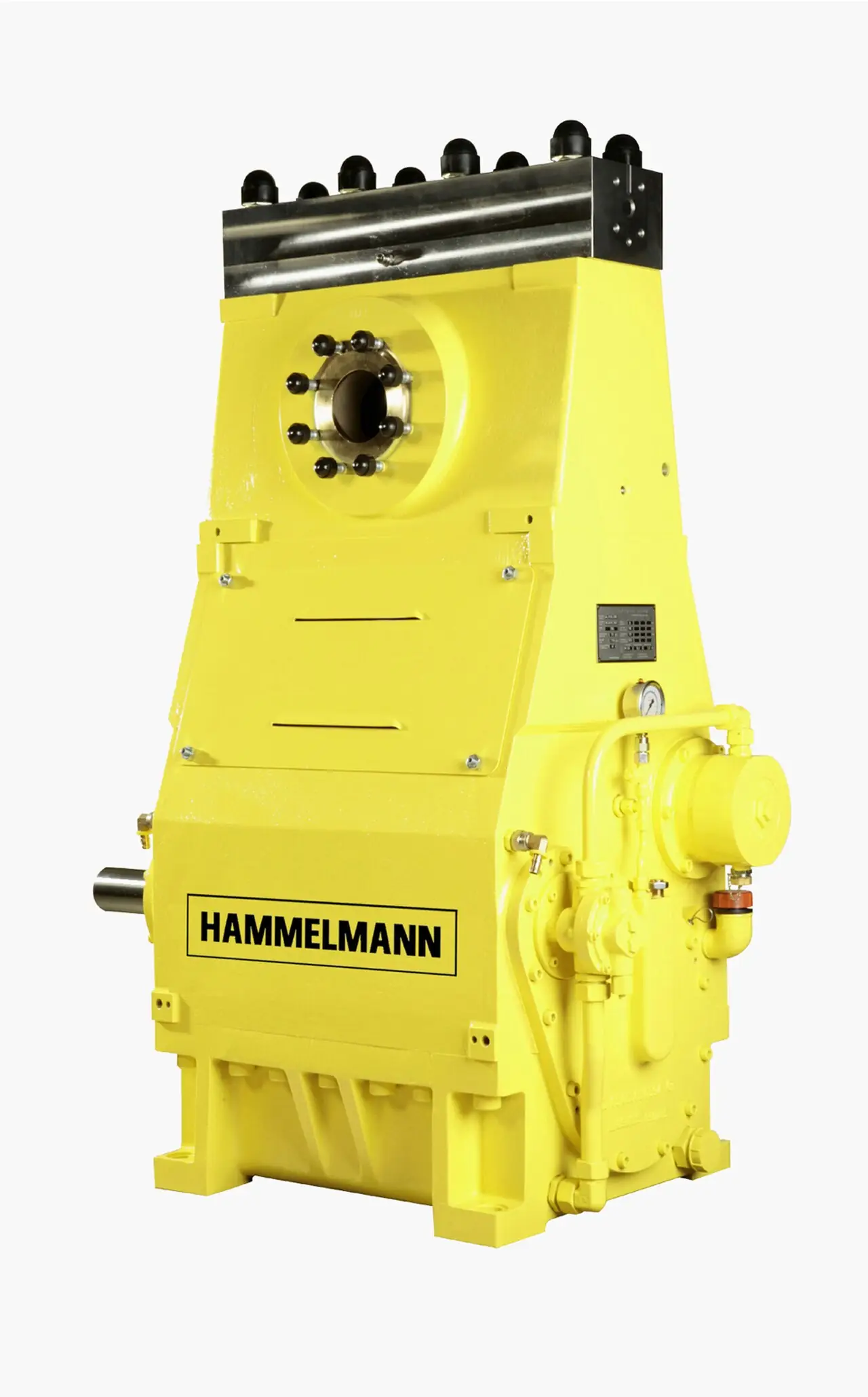
A reciprocating compressor is a positive displacement machine in which a piston travels in a cylinder, driven by a crankshaft through a connecting rod, the slider-crank architecture the reciprocating engine made universal. Suction and discharge are controlled not by timing but by passive valves, reed or plate, that open on a small pressure differential in the correct direction and slam shut on reversal. Compression per stroke is close to adiabatic, which lets one cylinder tolerate a high pressure ratio: about 4 to 8 per stage is the practical family band for air and ordinary gases. That is why a small two stage shop unit reaches 10 to 12 bar in one frame, a breathing air plant reaches 200 to 330 bar in three or four stages, and API 618 process frames build 100 to 700 bar and above in 4 to 6 stages, with ethylene hyper compressors above 3,000 bar as the extreme niche.
Procurement engineers meet these machines as workshop and garage air units on receivers, as oil-free piston compressors feeding food, medical, and laboratory air, as high pressure breathing air and CNG stations, and as separable balanced-opposed API 618 frames on natural gas gathering, hydrogen make-up, CO2, and refinery duty. The decision this page settles is the one that drives every line of the purchase order: how many stages and how much intercooling the duty needs, lubricated or oil-free construction, what capacity control matches the demand profile, how the pulsation that a piston machine cannot avoid is contained, and what part of the API stack the specification must invoke when the gas is process gas rather than air. The answer lands as an RFQ line set: gas and molecular weight, flow at stated reference conditions, suction and discharge pressure, stage count, cooling, driver and control scope, and the pulsation and protection package.
This page treats the reciprocating compressor as a purchasing object: the slider-crank mechanism and the valve as the number one failure, staging and intercooling arithmetic, clearance volume and capacity control, pulsation bottles and the API 618 study that sizes them, and how all of it is written into an RFQ. It is written for engineers who issue purchase specifications, not for readers who want a brochure summary.
Chapter 1 / 06
What a Reciprocating Compressor Is and What Is Being Decided
The defining hardware is the cylinder and its valves. A piston sealed by rings travels between crank-end and head-end dead centers; on the outward stroke the cylinder pressure falls a few percent below suction line pressure and the suction valve plates lift; on the return stroke the suction valve closes on flow reversal, the trapped gas is compressed along a near-adiabatic path until cylinder pressure exceeds the discharge line, and the discharge valve lifts to push the charge out. Neither valve is actuated or timed: each is a spring-loaded plate or reed that responds only to the pressure difference across it, and this simplicity is both the architecture's strength and its Achilles heel, because valve plates and springs are consumables and valve failure is the single most frequent breakdown across the whole family. The machine is a positive displacement device in the strict sense: per revolution it displaces a fixed cylinder volume, and the gas leaves because it must, almost without regard for what the discharge system does, which is the opposite of a dynamic machine's head curve behavior.
What is actually being decided in this purchase is six commitments at once. First, the gas and duty commitment: air or process gas, its molecular weight and composition range, suction pressure and temperature, discharge pressure, and capacity at declared reference conditions, because staging and frame selection follow from those numbers alone. Second, the lubrication commitment: lubricated cylinders with oil in the gas path, or oil-free piston construction with PTFE or rider ring materials, which decides downstream air treatment and maintenance economics. Third, the staging commitment: stage count, per stage ratio, intercooling type, air cooled or water cooled, which set efficiency and discharge temperatures. Fourth, the control commitment: start-stop with receiver, suction valve unloaders, clearance pockets, VFD speed, or recycle, matched to the demand profile. Fifth, the pulsation commitment: bottles, orifices, and pipe support design backed by a pulsation study, without which the piping cracks and the instruments lie. Sixth, the code commitment for process gas: the API 618, API 614, API 670 stack and its documentation burden, or its absence for a shop air unit where none of it applies. A quotation that answers only kilowatts and bar has answered the least important questions.
Against its neighbors, boundaries must be drawn early, and this page does not replace the dedicated leaves for those neighbors. The screw compressor, covered by its own encyclopedia page, is the default 30 to 500 kW plant air machine, continuous in duty, quieter, with oil carryover handled by treatment on lubricated builds; where shop air demand grows past a few tens of kilowatts, the screw answer usually wins and this page does not argue otherwise. The centrifugal compressor, also covered by its own page, owns oil-free air and gas above a few hundred kilowatts where flow is high and steady, trading the piston's pressure capability for dynamic staging. A regenerative blower serves clean low pressure air below about 0.5 bar g, a roots blower serves bulk low pressure at modest ratios, and a vacuum pump of the reciprocating or other kind serves the sub-atmospheric side. One boundary deserves particular honesty because the hardware looks so similar: the live encyclopedia page for the plunger pump covers a liquid positive displacement pump, a machine that moves incompressible liquid with check valves sized for liquid dynamics. It shares the slider-crank architecture with this page, crankcase, connecting rod, crosshead in the bigger frames, but it is a different product, bought against pump standards, not a gas compressor by another name.
Four standards organize the datasheet. API 618 governs reciprocating compressors for petroleum, chemical, and gas industry service: frame ratings, distance pieces, pulsation and vibration study expectations, testing, and documentation. API 614 governs the lubrication system those frames depend on, and API 670 governs the machinery protection instrumentation that watches them. On the air side, ISO 1217 fixes the acceptance test and reference conditions behind every free air delivery figure, and where the gas is sour, NACE MR0175 with ISO 15156 governs material selection. A process datasheet that quotes none of the first three is a price tag, not a specification, and an air datasheet that does not state its ISO 1217 basis is quoting a number nobody can verify.
Compressed to one sentence, the RFQ decision is whether the duty is bought as a thermodynamic and mechanical system, staging matched to the gas, valves and rings matched to the gas cleanliness, pulsation contained by design rather than by hope, and protection matched to the consequence of a stop, or as a nameplate connected to the nearest header. The chapters that follow supply the cylinder physics, the frame families, the datasheet rows, the selection logic, and the failure modes needed to write it the first way, keeping every number at the cautious family level a procurement file can defend.
Chapter 2 / 06
How the Piston Compresses, and Why Pulsation Exists
The kinematics are the same slider-crank family the plunger pump and the piston engine use: crank rotation converts to nearly sinusoidal piston travel, so piston velocity is zero at each dead center and maximum near mid-stroke. Swept volume per cylinder per revolution follows from bore and stroke, and frame speed spans roughly 400 to 1,800 rpm family-wide, with small air units at the top of the band and heavy process frames at 300 to 800 rpm class. Flow into and out of the cylinder therefore pulses at the crank frequency and its harmonics: a single-acting cylinder pulses once per revolution, a double-acting cylinder twice with unequal peaks from the rod side, and a multicylinder frame interleaves them without ever producing the smooth delivery of a rotary machine. This pulsation is not a defect; it is the mechanism's signature, and everything from bottle sizing to instrument placement in chapters 4 and 6 exists to manage it.
The valves are passive and self-acting, and their dynamics decide both efficiency and life. A plate or reed valve lifts against its spring by roughly 1 to 2.5 mm family-typical, and the spring load is matched by the manufacturer to the frame speed and the gas: too soft and the valve flutters, hammering its plates and seats; too stiff and it opens late and closes early, throttling the gas and heating it. Valve efficiency loss appears as elevated discharge temperature and reduced capacity, which is why per cylinder discharge temperature is the primary health trend on any piston machine. Gas properties matter directly: a valve set tuned for air does not necessarily behave on hydrogen or CO2, and process frame makers tune valve geometry and springing to the declared gas and its molecular weight, one more reason the RFQ must state the gas honestly.
The thermodynamics of the stroke explain staging. Compression along a near-adiabatic path with a specific heat ratio near 1.4 for air means discharge temperature rises steeply with pressure ratio: in words, the temperature ratio tracks the pressure ratio raised to the power determined by that specific heat ratio, minus intercooling. A discharge temperature ceiling of roughly 150 to 180 deg C governs practice, set by lubricant degradation on lubricated cylinders and by ring and valve materials on non-lube builds, and that ceiling is what limits the per stage ratio to the 4 to 8 practical band for air and knocks it down for high ratio of specific heats gases and raises it for heavy gases. The second stroke-side effect is clearance volume: the space left at dead center between piston, valve plates, and head, typically 4 to 12 percent of swept volume in industrial cylinders, re-expands on the suction stroke before any new gas enters. Volumetric efficiency, in words the fraction of swept volume actually refilled with fresh gas, falls as pressure ratio rises and as clearance grows, which is why high ratio service demands more cylinders rather than one cylinder pushed harder, and why clearance pockets work as a capacity control at all.
Staging and intercooling convert the ratio into hardware. The economic design splits the total ratio across stages so that each stage carries a similar ratio and discharge temperature, with an intercooler between stages rejecting heat so the next stage starts dense again; the closer the path to isothermal, the less total work the duty costs, at the price of coolers and pressure drops between stages. The family arithmetic is familiar: single stage small units reach 8 to 10 bar in one cylinder on light duty, two stage shop and plant machines reach 10 to 12 bar in the 2.5 to 10 kW class, three and four stage breathing air plants build 200 to 330 bar with purification downstream, and process frames stack 4 to 6 stages for 100 to 700 bar, with ethylene hyper compressors above 3,000 bar as the laboratory-grade extreme that exists only for LDPE duty. Every intercooler and aftercooler is also a condenser: on humid gas the knockouts must drain, and on process frames the suction scrubber drains on a schedule, because liquid slugging is on the short list of things that break a cylinder outright.
Pulsation containment is a design discipline, not an accessory. The pressure pulses propagate into the piping as acoustic waves, and where pipe lengths resonate, standing waves amplify small cylinder pulses into pipe-shaking, gauge-breaking, weld-fatiguing dynamic pressure. The countermeasures, in the order they are usually applied: suction and discharge volume bottles sized by an acoustic study, the API 618 pulsation and vibration analysis performed by analog or digital simulation; orifice plates at bottle nozzles to damp the standing waves; and pipe supports and restraint placed where the study says, not where the pipefitter prefers. A gas-charged bladder accumulator style dampener appears on smaller and liquid-slugged services where a bottle alone is not enough. The instruments suffer first when pulsation is left raw: an orifice or vortex flow meter reads fiction in an oscillating stream, and a pressure transmitter connected by an un-damped impulse line chases the pulse instead of reporting the mean, so the study protects the measurement chain as much as the welds.
Capacity control exists because the machine displaces fixed volume per revolution into variable demand. The small air answer is start-stop against a receiver pressure band, bounded by motor thermal limits, with duty cycle rules of roughly 60 to 70 percent maximum on many single stage and light two stage units, and continuous rated versions specified where the demand never rests. The frame-level answers unload the machine without stopping it: suction valve unloaders hold the suction valve plates open so the cylinder pumps nothing but its clearance gas; clearance pockets, fixed or variable volume, add clearance and cut volumetric efficiency deliberately; stepless variants trim continuously between steps. On process frames, recycle or bypass control sends discharged gas back to suction through a cooler, wasteful but always available, and a VFD on the driver moves capacity with speed across a finite band while changing the pulsation spectrum the study must cover. A soft starter limits inrush on fixed speed machines where the supply is weak or the starts are frequent. The honest specification names the control method and its consequences together, because an unloader changes rod load and a pocket changes temperature rise, and each has a limit the datasheet must state.
Chapter 3 / 06
Frames, Construction, and Duty Boundaries
The shop and plant air piston compressor is the volume product of the family. Single acting and single stage machines serve small tools to about 8 to 10 bar at a few kilowatts; two stage machines, usually a large low pressure cylinder and a smaller high pressure cylinder in V or inline arrangement, belt or direct driven, cover the 2.5 to 10 kW class to 10 to 12 bar, the L range of leaflet-class catalogs being representative; and legacy three stage machines carried 15 bar and above before rotary machines took the mid range. Lubrication is splash on light units and pressure feed above roughly 5 kW, with an oil pump and filter on the larger builds. Most ship receiver-mounted on a 90 to 300 L tank with an aftercooler or at least a discharge line hot enough to warn the careless, and the air leaving a lubricated piston machine carries oil aerosol that downstream filtration and the air dryer, covered by its own page, must be sized to strip.
The oil-free piston compressor removes oil from the gas path entirely: piston rings and rider rings of PTFE composites, or in laboratory and medical niche builds labyrinth pistons running against scored cylinders with no contacting rings at all, with the crankcase sealed from the cylinder by distance pieces and packing. The reward is air that meets oil-free classes by construction; the price is ring and rider wear as the primary consumable, tighter inlet filtration, and discharge temperature discipline, since non-lube cylinders have less margin for abuse than their lubricated siblings. These machines serve food and beverage air, medical and dental plants, laboratory benches, and process air where any oil is a contamination event rather than a nuisance, and the buyer trades the lubricated machine's valve-and-oil maintenance for a ring-and-rider maintenance calendar.
The high pressure end is staging turned into hardware. Breathing air and SCBA filling plants run three or four stages with intercooling, condensate traps, and a purification train of molecular sieve and carbon to reach 200 to 330 bar breathable quality, bought against breathing air purity rules rather than general plant air classes. CNG mother and daughter station compressors run three to five stages to 250 bar class dispensing. Field service and gas gathering frames compress wellhead gas, flare gas recovery, and vapor with suction pressures that swing daily, which is why capacity control and rod load margins dominate those datasheets. At the extreme, ethylene hyper compressors, the 1,000 to 3,000 bar class machines of LDPE plants, are their own engineering world with combined crank and secondary hydraulic actuation, and they appear here only as a boundary marker for what the family can be pushed to do.
The API 618 process frame is the heavy end and the most specified. A separable balanced-opposed frame puts opposed cylinders on a shared crankshaft so inertia forces cancel, running in a bedded or skid-mounted crankcase with a crosshead between connecting rod and piston rod, so the piston rod is loaded in tension only and the packing case can be sealed and vented. Distance pieces, short or long with a vented intermediate chamber, isolate cylinder gas from the crankcase for toxic and flammable service, and the specification chooses the type against the gas hazard. Cylinders carry clearance pockets and stepless volume control for capacity; packing cases, piston and rider rings, and valves are tuned to the declared gas molecular weight; drivers are induction motors, fixed speed or with VFD, or gas engines on remote sites; and the frame is rated by rod load in kilonewtons and speed, which chapter 4 turns into the two numbers the datasheet must not fudge. Integral engine compressors, where power and compression cylinders share one crankshaft, survive in gathering legacy and niche duty and are otherwise a historical note. Hyper compressors were covered as a boundary above and are not a catalog row.
The type table compresses the family into the form a specification meeting argues from; values are common spans of the established families and must be confirmed against the model datasheet before order.
Frame family
Construction
Pressure and power class
Duty it wins
Single and two stage shop air unit
V or inline cylinders, belt or direct drive, receiver mounted, splash or pressure lube
8 to 12 bar, about 1 to 10 kW, duty cycle 60 to 70 percent typical
Workshop, garage, light plant air
Oil-free piston compressor
PTFE ring and rider or labyrinth cylinders, distance piece, sealed crankcase
7 to 10 bar common, small to mid power
Food, medical, dental, laboratory oil-free air
High pressure multi-stage plant
3 to 4 stages with intercoolers, traps, purification
100 to 700 bar class, 4 to 6 stages, hundreds to thousands of kW
Gas gathering, hydrogen, CO2, refinery make-up
Hyper compressor
Special combined actuation, laboratory-grade tolerances
1,000 to 3,000 bar class
LDPE ethylene duty only, a boundary case
Duty boundaries keep the frames honest against each other. The piston machine earns its place wherever pressure per stage, pressure ceiling, or gas variety beats the rotary alternatives: it holds the high pressure and small oil-free niches outright, and it serves intermittent and remote duty where its valve maintenance is tolerable. It loses the continuous mid-size plant air station to the screw machine on noise, oil carryover, and duty cycle, and it loses large steady oil-free flow to the centrifugal machine. The vacuum pump sibling family covers sub-atmospheric duty with its own page. Stating the boundary in the specification meeting is cheaper than discovering it at commissioning.
Chapter 4 / 06
Key Specification Parameters
The datasheet rows below decide whether a quoted machine matches the duty; values are stated as the common industrial spans of the established families and must be confirmed against the model datasheet and its ISO 1217 or API 618 test basis before order.
Attribute
Typical range or options
What it decides
Gas and molecular weight
Air, natural gas, hydrogen rich, CO2, process mixes with stated range
Valve tuning, ring materials, staging, and NACE applicability
Suction and discharge pressure
Atmospheric to 330 bar air duty; 100 to 700 bar process class
Total ratio, stage count, casing and piping class
Capacity at reference
FAD per ISO 1217 for air; stated reference conditions for gas
Cylinder count and size, and the verifiable flow guarantee
Stages and per stage ratio
4 to 8 per stage practical; 2 stage shop, 3 to 4 stage high pressure, 4 to 6 process
Discharge temperature margin and intercooler count
Discharge temperature limit
150 to 180 deg C practice ceiling by lube and ring type
The wall the staging design pushes against
Frame speed
About 400 to 1,800 rpm family; 300 to 800 rpm heavy process
Capacity, valve life, and inertia loads
Allowable rod load
Frame rated in kN, combined gas plus inertia, with margin stated
Whether the duty point lives inside the frame's envelope
Lubrication of gas path
Lubricated cylinders, or non-lube PTFE and rider rings, or labyrinth
Downstream oil treatment versus ring wear calendar
The rod load row deserves a paragraph because it is the number that keeps honest frames honest. The piston rod sees gas load, discharge area times pressure difference, and inertia load, which grows with the square of speed; the combined load must sit inside the frame's allowable rating at every point of every stroke, at maximum credible suction and discharge pressure, not just at the datasheet operating point. Underspecified rod load margin is how a machine that passes the flow calculation still breaks its rod or wrecks its crosshead in year two when the suction pressure rises or the control system unloads asymmetrically. The second quiet number is volumetric efficiency: clearance volume and ratio together decide what fraction of the swept volume the cylinder actually pumps, so two machines with identical bore and stroke can deliver visibly different capacity at high ratio. Ask for the capacity calculation per stage, not a headline FAD figure.
The instrumentation, valve, and protection rows decide whether the machine survives its own pulsation and transients, and the table below states the set that belongs in scope, whoever supplies it.
Duty point
Instrument or valve
Function
Stage pressure trend
Pressure transmitter per stage suction and discharge
Service and lockout without dropping the plant header
Electrical inrush
Soft starter on fixed speed motors
Starts per hour and weak supply compatibility
Speed control
VFD on the driver where speed turndown is chosen
Capacity follows demand with the pulsation study updated
What the datasheet must state, in plain terms: gas composition and molecular weight range with the worst case named; suction pressure and temperature, discharge pressure, and capacity at declared reference conditions with the ISO 1217 basis for air; stage count with per stage ratio and each intercooler's approach; discharge temperature design values per stage; rod load rating and the calculated load at the duty point with margin; valve type and materials with the gas they are tuned for; lubricated or non-lube construction with ring materials; capacity control method with its limits; cooling type, duty, and water quality expectations; the pulsation study scope and bottle sizing basis; distance piece type where the gas is toxic or flammable; and the protection set, pressure and temperature transmitters, safety relief valve count and settings, vibration monitoring on process frames, with alarm and trip values. A quotation without the rod load and the per stage temperature numbers is incomplete at any price.
Chapter 5 / 06
Selection Decision Factors and RFQ Language
The selection sequence runs as a checklist, and each line eliminates a class of quotations before price comparison begins.
Fix the gas honestly: composition, molecular weight range, contaminant and sour service flags, because valves, rings, materials, and NACE applicability follow from the gas, not the flow.
State suction pressure and temperature, discharge pressure, and capacity at declared reference conditions, with the worst credible combination marked, not just the nominal.
Choose staging: per stage ratio inside the 4 to 8 practical band and the 150 to 180 deg C temperature ceiling, with intercooling type and approach stated per stage.
Choose the gas path: lubricated cylinders with downstream oil treatment, or non-lube PTFE and rider ring construction with its maintenance calendar; state the air or gas purity class required.
Check rod load and speed at the duty point and at the worst case, with margin stated by the supplier, not assumed by the buyer.
Choose capacity control against the demand profile: start-stop with receiver, unloaders, pockets, VFD, or recycle, and state the duty cycle rule the machine must live within.
Fix the pulsation scope: bottles per the API 618 study, orifices, and pipe supports, with the study named as a deliverable on process duty.
Fix the protection and code scope: API 614 lubrication and API 670 monitoring on process frames, distance piece type for the hazard, and the documentation package the jurisdiction demands.
Against the neighboring machines the piston compressor holds specific ground, and the comparison belongs here in the selection chapter rather than in a page title. The screw compressor wins continuous plant air from roughly 30 to 500 kW on noise, oil carryover that treatment can manage, and duty cycle, and it is the honest default wherever the demand is steady and mid-sized. The centrifugal compressor wins oil-free air and gas above a few hundred kilowatts at high and steady flow, where its specific power and capacity to scale put cylinder count out of reach. A regenerative blower serves clean low pressure air, a roots blower serves bulk low pressure, and neither reaches a tenth of the pressure a single piston stage takes for granted. Below atmospheric pressure the vacuum pump family takes over with its own pages. In the liquid world, the plunger pump is the same slider-crank logic applied to incompressible duty, and it shares maintenance patterns, packing and valve consumables, without sharing a single standard with the gas side. The reciprocating compressor earns its cost where pressure per stage, pressure ceiling, gas variety, or intermittent and remote duty outweigh its noise, its pulsation plumbing, and its valve maintenance calendar.
The application map below compresses the practice into the form a project file carries.
Application
Construction to specify
Check before order
Workshop and garage air
Two stage receiver-mounted unit, 2.5 to 10 kW class
Duty cycle rule and motor starts per hour limit
Food, medical, laboratory oil-free air
Non-lube piston machine, staged filtration, air dryer for dew point
Oil-free class evidence and ring wear interval
Breathing air and SCBA filling
3 to 4 stage plant with intercoolers, traps, and purification train
Carbon monoxide and moisture limits with purification proof
Natural gas gathering and field boost
API 618 balanced-opposed frame, clearance pockets, driver for the site
Pulsation study scope and rod load at swing suction pressure
Hydrogen make-up and refueling precompression
Multi-stage non-lube or minimum lube cylinders, sealed packing
Leak detection, ring materials, and per stage temperature margin
CO2 capture and injection duty
Multi-stage frame with intercooling and dehydration awareness
Wet CO2 materials and condensate management between stages
CNG station compression
3 to 5 stage frame to 250 bar class dispensing
Capacity control across daily demand swing and inlet variation
The RFQ block should be written once and reused: gas composition and molecular weight range with sour service flag; suction pressure and temperature, discharge pressure, and capacity at declared reference conditions, ISO 1217 basis for air; stage count, per stage ratio, intercooler type and approach, and design discharge temperatures; lubricated or oil-free construction with ring, rider, and packing materials named; rod load rating and calculated duty point load with margin; frame speed and driver, with VFD and soft starter scope where chosen; capacity control method and limits with duty cycle statement; cooling type, duty, and water quality where water cooled; pulsation and vibration study scope with bottle and orifice deliverables, per API 618 on process duty; distance piece type and packing vent arrangements for toxic or flammable gas; instrumentation set with alarm and trip values, safety relief valve settings, and API 670 monitoring scope on process frames; spare parts, valve sets, ring and rider sets, packing, gaskets, named on the order; and the test and documentation requirements of the code jurisdiction. A quotation returned without the staging calculation and the rod load margin is incomplete at any price.
Chapter 6 / 06
Installation, Standards, Failure Modes, and Maintenance
Installation quality decides whether the frame reaches its overhaul interval. The foundation carries the unbalanced forces a reciprocating machine cannot fully cancel: small units sit on tanks and pads, while process frames demand a concrete inertia block of typically two to five times machine mass, isolated from the structure, because what the balanced-opposed geometry leaves over must be absorbed by mass rather than transmitted to the building. Piping follows the pulsation study, not the convenient route: bottle nozzles, orifice locations, and support points are deliverables from the study, and every support omitted is a weld fatigue test the plant did not budget for. The suction side gets a scrubber or knockout that actually drains on humid gas and process duty, because liquid slugging bends rods, and the final discharge gets its check valve at the header connection so a tripped machine is not backdriven by the plant. Cooling circuits are commissioned properly: water cooled jackets and intercoolers have their Y strainer cleaned after first circulation, and the air release valve at the circuit high point is cracked open at every cold start so the thermosyphon paths do not run airlocked and let a cylinder overheat quietly. Isolation hardware, ball valve at suction and discharge, butterfly valve on large atmospheric intakes, is placed for lockout so a valve job does not require a plant shutdown. On gas engine driven remote frames, the fuel gas line takes its pressure reducing valve and filtration at the skid edge so the engine sees steady pressure regardless of wellhead swings.
Commissioning earns the guarantees. Baseline the machine under load: per stage suction and discharge pressures from each pressure transmitter, per cylinder discharge temperature from each temperature transmitter, rod drop where the frame instrument provides it, and vibration at the declared measurement points. Verify capacity at the reference conditions against the ISO 1217 or agreed gas basis, with the flow measurement made far enough from the machine that pulsation has decayed or been damped. Prove the protection: lift the safety relief valve settings on paper against the code calculation, force every alarm and trip path once, and stroke every unloader and pocket so the capacity control actually moves. Where the driver carries a VFD, run the speed band against the pulsation study's frequency coverage; where the motor starts across the line, count the starts per hour against the thermal limit of both motor and frame. A commissioning record with those lines turns the first turnaround inspection into a formality.
The standards frame is layered. API 618 governs the process machine: frame and cylinder design expectations, pulsation and vibration study requirements, testing, and the data books the buyer receives; its lubrication system is governed by API 614 and its protection by API 670, and the three are bought together or the gaps are bought later at a premium. On the air side, ISO 1217 fixes the acceptance test and reference conditions behind the FAD figure. Sour service pulls in NACE MR0175 with ISO 15156 for material selection. Pressure piping follows the site's code, ASME B31.3 being the usual process answer, and receivers and coolers fall under the local pressure equipment rules, PED in Europe as the common evidence. Breathing air plants inherit their own purity rules rather than general plant air classes. Naming the standards in the RFQ transfers the burden of proof to the supplier, which is where it belongs.
Failure modes follow a short and predictable list. Valve failure is first and it is not close: coked, corroded, or fatigued plates and springs raise discharge temperature and cut capacity, caught by the per cylinder temperature transmitter trend long before the machine stops; the remedy is a valve set, and the spares shelf holds them from day one. Packing wear on high pressure stages shows as gas leakage at the distance piece vent, detected by sight, smell, or a leak detector on hazardous gas, and repacking is a planned job with the packing case inspected. Rider ring wear on non-lube cylinders lets the piston sag and score the liner, watched on frames that provide rod drop measurement and estimated by interval on those that do not. Pulsation fatigue cracks piping at welds when bottles or supports fail, and the fix is the study, redone, not more weld. Liquid slugging from un-drained scrubbers and intercoolers breaks internals outright, which is why drainage is on the daily list. Lubrication failure on pressure feed frames wipes crossheads and bearings in minutes, which is what the API 614 system and its alarms exist to prevent. And dirt kills rings and liners through the inlet path, so inlet filtration is a purchase decision that returns itself within one ring set.
Maintenance is budgeted in consumables and trends. Daily: drain the scrubber, traps, and receiver, and read the stage pressures and cylinder discharge temperatures against baseline. Weekly: oil level and, on lubricated cylinders, feed rate against the maker's drops per minute table. Quarterly: valve inspection on the first scheduled stop after any temperature excursion, cooling side cleaning, and check valve exercise. Annual or by running hours: valve set replacement on schedule rather than on failure, ring and rider measurement against wear limits, packing adjustment or replacement, bearing clearance checks, and a full protection functional test; on water cooled machines, jacket and intercooler inspection with the Y strainer serviced. Spares on site: at least one full valve set per frame plus one per two cylinders on continuous duty, ring and rider sets, one packing set per pressure stage, gaskets and filter elements, and the instrument spares the protection philosophy names. Hyper and large process frames follow maker-specific interval logic beyond this page's family guidance. Held to that rhythm, the machine's one real weakness, that it wears its valves and rings by design, becomes a scheduled line item instead of the reason the plant stood still.
FAQ
How high a pressure ratio can one cylinder stage take?
About 4 to 8 per stage is the practical family band for air and ordinary gases, set by the discharge temperature ceiling of roughly 150 to 180 deg C rather than by mechanical strength. Above that band the gas leaves the cylinder too hot for lubricant, rings, and valves, so the design adds stages and intercoolers instead of pushing one cylinder harder. Heavy gases tolerate somewhat more ratio per stage and light, high specific heat ratio gases somewhat less, which is why the RFQ must state the gas.
Why do reciprocating compressors need pulsation bottles?
The piston delivers flow in pulses at the crank frequency and its harmonics, and those pulses travel into the piping as acoustic waves. Where pipe lengths resonate, standing waves amplify the pulses into dynamic stress that cracks welds and into oscillation that makes an orifice or vortex flow meter and a pressure transmitter read fiction. Suction and discharge volume bottles, orifices, and supports, sized by the API 618 pulsation study, keep both the mechanical stress and the measurement error inside limits on process duty.
Lubricated or oil-free piston construction for food and laboratory air?
Oil-free construction, PTFE ring and rider cylinders with distance pieces, is the honest answer where any oil is a contamination event, because purity comes from architecture rather than from a filter stage. The trade is the maintenance calendar: non-lube rings and riders are the primary consumable, inlet filtration must be tighter, and discharge temperature discipline matters more. Lubricated machines cost less to buy and maintain where oil aerosol downstream is tolerable and treated.
What is a distance piece and when do I need one?
A distance piece is the spacer between cylinder and crankcase on process frames, keeping crankcase oil and atmosphere away from cylinder gas; short versions suit neutral duty, long vented versions isolate toxic and flammable gases with a buffered and drained middle chamber. Specify the type against the gas hazard in the RFQ, because it is a casting decision that cannot be retrofitted cheaply. It is also where packing leakage is collected and detected on high pressure stages.
How does capacity control work on a piston machine?
Small air units start and stop against a receiver band within a duty cycle limit, typically 60 to 70 percent on light machines. Frame-level options hold the machine running at reduced capacity: suction valve unloaders hold valve plates open so the cylinder displaces nothing, clearance pockets add re-expansion volume and cut volumetric efficiency deliberately, a VFD moves capacity with speed, and recycle bypasses discharged gas to suction on process duty. Each method changes rod load or temperature rise, so the datasheet must state its limits.
What is the number one failure and how do I catch it early?
Valve failure: coked, corroded, or fatigued plates and springs account for more unplanned stops than every other cause combined on most fleets. The early signal is a rising per cylinder discharge temperature and drifting interstage pressures, both visible in the temperature transmitter and pressure transmitter trends long before capacity collapses. Keep one full valve set on the shelf, replace on the scheduled interval rather than on failure, and log every excursion against its cylinder.
What do API 618, 614, and 670 actually buy me?
API 618 governs the reciprocating compressor itself for petroleum, chemical, and gas service: frame and cylinder design expectations, the pulsation and vibration study, testing, and the documentation package. API 614 governs the pressurized lubrication system that prevents crosshead and bearing wipes, and API 670 governs the machinery protection instrumentation with alarm and trip logic. Buying the three together closes the gaps that otherwise appear at startup as undocumented studies, missing alarms, and quarrels over scope.