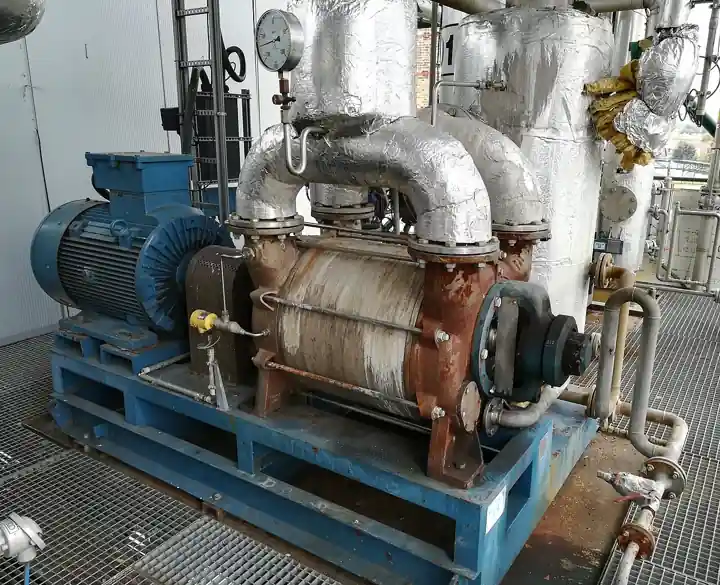
A dry claw vacuum pump is an oil-free positive displacement vacuum machine: two claw shaped rotors turn in opposite directions inside an oval casing, synchronized by precision timing gears so the claws never touch each other or the casing wall. Gas is carried in the chamber formed between each claw and the cylinder, compressed internally as that chamber shrinks, and expelled through the discharge port; no oil ever enters the pumping chamber, and no water either, because the gear and bearing oil stays sealed in its own gearbox. The class is the rough vacuum workhorse of packaging halls and central vacuum plants: ultimate pressures of about 0.5 to 10 mbar and pumping speeds of roughly 100 to 1000 m3/h across the family, with a characteristically flat speed curve across the working band. Industry also calls the machine a claw vacuum pump, a dry claw pump, or an oil free claw vacuum pump.
Procurement engineers meet these pumps on thermoforming and tray sealingpackaging machines, holding parts down on CNC routers, degassing extruders and resin dryers, serving central vacuum plants that replace banks of oil sealed vanes, lifting glass and stone, and feeding paper handling lines. The decision this page settles is narrow and practical: whether the duty fits a claw against the vane, screw, and liquid ring alternatives, whether one stage or two claw stages are needed for the depth, whether air or water cooling matches the ambient and the duty cycle, and what the RFQ must state about dust, condensate, and continuous rating. The answer lands as an RFQ line set, and every chapter below feeds that line set.
This page treats the dry claw vacuum pump as a purchasing object: how two contact free claw rotors reach rough vacuum with an oil-free chamber, what pumping speed and ultimate pressure numbers actually promise, which cooling and drive variants survive which ambient and duty cycle, and how protection hardware, monitoring, and ATEX documentation combine into a defensible RFQ. It is written for engineers who issue purchase specifications, not for readers who want a brochure summary.
Chapter 1 / 06
What a Dry Claw Vacuum Pump Is and What Is Being Decided
The geometry is the product. Each rotor carries a claw shaped lobe with a matched cutout; as the pair counter-rotates, the cutout of one rotor opens a chamber that draws gas from the inlet port, the chamber closes as the claws re-engage, and the trapped volume shrinks toward the discharge port in a built in compression cycle. Ports are uncovered and covered by the rotor edges themselves, so there are no valves inside the pumping chamber on most designs. The rotors are held apart by timing gears with clearances of a few hundredths to a tenth of a millimetre; that is why the machine runs for years on clean duty and seizes in an instant on a bolt that gets past the inlet screen.
The boundary with the dry screw vacuum pump is geometry, and it decides both price and depth. Screws convey gas axially along long helical flutes with almost no internal compression; claws move gas in short crescent chambers with real internal compression, which is efficient per stage in the rough vacuum band but reaches a coarser ultimate pressure. The claw consequently owns the packaging hall and the central plant where 0.5 to 10 mbar class depth is enough; the screw owns the deeper chemical and coating duty. Both are oil free in the pumping chamber, and both protect their gear oil behind shaft seals, a family trait this page shares rather than disputes.
What is actually being decided in this purchase is a match between a duty profile and a dry chamber machine. The buyer commits to pumping speed at the working pressure rather than at the catalog ultimate, to single or two stage claw construction, to a cooling mode against ambient temperature and duty cycle, to protection hardware against dust and condensate, and to a drive philosophy, fixed speed or variable speed, that matches the demand profile. Each decision has a datasheet row in chapter 4 and a failure story in chapter 6, and each is cheaper to make correctly at RFQ stage than at commissioning.
The neighbor map is worth drawing early, with the full comparison reserved for chapter 5. The rotary vane pump is the incumbent on packaging machines, oil sealed, cheaper on first cost, and burdened with oil mist, oil purchase, and disposal. The liquid ring vacuum pump tolerates condensable slugs that would wet a claw chamber, at the price of a water circuit. The roots blower is a booster that stages above any rough vacuum machine for depth and speed. A regenerative blower covers coarse vacuum at high flow where millibar depth never mattered. A vacuum generator, the compressed air venturi, belongs at intermittent workstation duty only. And two naming traps wait for the careless RFQ: the screw compressor compresses above atmospheric pressure, and the screw pump moves liquid; neither belongs in a vacuum specification.
Standards honesty comes early because there is no single ISO or API product code for claw vacuum machines. The industry reference points are PNEUROP guidance on how vacuum pump performance data is stated, IEC 60034 for the motors, the ATEX equipment directive where zones apply, and CE or UKCA machinery conformity for the package. What the standards do not fix, the purchase document must: the speed curve basis at a stated gas and temperature, the noise measurement position, and the acceptance values at commissioning. Those three buyer written lines are what make two quotations comparable in this product class.
The pump never works alone, and the RFQ should name its station. Inlet protection is a 100 micron screen and, on dusty duty, a cartridge filter with a differential indication. An anti-suckback check valve at the inlet holds vacuum when the machine stops; an isolation ball valve makes lockout possible. The discharge needs a silencer and, on condensable duty, a drain. Instruments are few and cheap: a pressure gauge at the inlet for the operator, an absolute pressure transmitter for the control system, and temperature monitoring inside the machine. Naming the station buys a system that starts on the first morning rather than the third.
Chapter 2 / 06
How the Claw Rotors Move Gas
Walk the cycle. As the claws counter-rotate, the cutaway of one rotor passes the inlet port and a chamber opens, filling with gas at suction pressure. Rotation seals that chamber off, and as the claws continue to interleave, the chamber volume decreases: this is internal compression, real work done on the gas before the discharge port is ever uncovered. When the port opens, the compressed gas leaves, swept out by the continuing rotation and assisted on some designs by the next chamber cycle. The overlap of the two rotor cycles gives an almost continuous delivery, which is the mechanical root of the low pulsation the class is known for.
Contact free timing is the whole reliability story. The rotors are geared together externally with a precision and a backlash set at assembly; the working clearance between claw flanks and casing, a few hundredths to a tenth of a millimetre class, is never closed in normal operation. The gears and bearings run in an oil bath sealed away from the pumping chamber by shaft seals and, on many builds, a purge connection between them. The machine is therefore dry at the process end and oily at the drive end, and maintenance keeps that distinction: gearbox oil is a scheduled consumable, chamber cleanliness is a process discipline.
Read the speed curve at the duty pressure, not at the brochure corner. Two characteristics distinguish the claw class. First, pumping speed stays close to its displacement across most of the rough vacuum band, from atmosphere down through the tens of mbar where packaging duty lives; an oil sealed rotary vane pump loses a growing share of its speed as pressure falls. Second, the ultimate pressure, about 0.5 to 10 mbar across the family, is a blanked off floor and not a working point. Select on the speed delivered at the process pressure with the gas and temperature stated, and keep the staging options of this chapter in reserve for depth.
Heat decides cooling. Every watt of compression work and every watt of motor loss ends in the casing, the rotors, or the gas. Air cooled designs reject it through fins and a fan and are the packaging standard up to a modest ambient; water cooled designs jacket the casing and hold geometry steadier under continuous heavy duty and in hot rooms. Overtemperature is the machine's own protection limit: claw machines monitor temperature internally and trip, because a hot casing closes clearances and a closed clearance is a seized rotor. Chapter 6 prices that trip in lost production against the water service that would have prevented it.
Contaminants set the survival rules. Fine dust that passes a screen still coats claws and chambers, so dusty duty, CNC router tables above all, runs behind a cartridge filter and accepts shorter service intervals. Condensable vapor tolerates the machine well: the crescent chambers pass liquid slugs poorly but drain condensate readily, and most builds carry a drain provision at the low point. Process vapor that would coat or polymerize calls for a purge connection, a timed solenoid valve admitting nitrogen or dry air to keep the chamber swept. Each protection is a line item in chapter 4 and a failure story in chapter 6.
Two extensions finish the picture. Staging: a roots blower mounted above the claw multiplies speed at the low end of the band and is the standard architecture where depth and capacity grow together; two claw stages on integral shafting, the arrangement behind the deeper MINK MV class machines, compound toward lower ultimate pressure without external staging. And drive: variable speed packages trim the machine to demand, which on central systems with a fluctuating profile is the single largest energy decision in the chapter, with maker claims in the 30 to 50 percent class against fixed speed banks of vanes.
Chapter 3 / 06
Types, Construction, and Duty Boundaries
Single stage claw machines are the volume product: one claw pair, one compression cycle, ultimate pressure in the 1 to 10 mbar class of the family, capacities across the 100 to 1000 m3/h band. They serve most packaging machines, hold down tables, and central plants directly. Two stage claw machines compound two claw pairs in series, usually on integral shafting in a common casing, and push the ultimate toward the deep end of the class; they are the specified answer when the process needs the extra margin but does not need a different technology. The Busch MINK MW and MV families and the Edwards nEDC line cited in the sources below define the commercial class.
Cooling variants split the catalog. Air cooled packages are self contained: fins, a shaft fan or a separate blower, no water service, and a modest ambient limit, typically quoted around a 40 to 45 deg C class. Water cooled jackets move more heat at a steadier casing temperature, buy back capacity margin in hot rooms and continuous duty, and add a utility with quality, flow, and freeze obligations of its own. The choice is a plant decision as much as a pump decision, and it belongs in the RFQ with the ambient and duty cycle stated next to it.
Materials are iron by default and coated by exception. Rotors and casings are grey cast iron across the mainstream class, correct for air and for the clean dry process gases that dominate packaging and hold down duty. Humid and mildly chemical duty buys special rotor and casing coatings, which some makers offer as a catalog variant; aggressive service belongs to other technologies discussed in chapter 5. The coating is not decoration: a corroded claw flank changes the working clearance directly, and clearance change is speed curve loss that no cheap repair recovers.
Drive packages finish the types. Fixed speed machines with an across the line starter are the simple answer to steady duty. Variable speed packages, the MINK B class pattern, pair the machine with an integrated drive and hold vacuum against a fluctuating demand by trimming speed, with the energy consequences of chapter 2 and the noise benefit at part speed. On machines that start against atmosphere every cycle, packaging duty above all, the start frequency is a motor and drive question that belongs in the RFQ, not in a footnote.
The boundaries are about the gas and the depth, not the machine. Below the claw class ultimate, stage a booster or change technology rather than demanding a deeper claw. Fine dust without filtration, liquid slugs without drainage, and polymerizable vapor without purge are the three duties that reliably kill the class, and chapter 6 prices all three. For intermittent point duty at a bench, a vacuum generator costs a fraction of any pump and spends shop air; for high flow coarse vacuum, a regenerative blower is the cheaper machine; and for the deepest oil free duty, the dry claw vacuum pump hands off to its screw cousin honestly. The variant table below consolidates the construction decisions.
Variant
What it changes
Where it is specified
Watch items
Single stage claw
One claw pair, one compression cycle
Packaging machines, hold down tables, central plants
Ultimate pressure floor of the family class
Two stage claw
Two claw pairs compounded toward deeper ultimate
Processes needing extra depth margin
Duty at the low mbar end; interstage drainage
Air cooled package
Fins and fan, no water service
Clean packaging duty, water scarce sites
Ambient limit near 40 to 45 deg C; fan noise
Water cooled jacket
Higher heat rejection, steadier clearances
Hot rooms, continuous heavy duty
Water quality, flow, and freeze protection
Variable speed package
Integrated drive trimming speed to demand
Central systems with fluctuating profile
Start frequency; control integration basis
Chapter 4 / 06
Key Specification Parameters
The table below decodes the datasheet lines that decide whether a quoted machine matches the duty. Each row is purchase defining; the paragraphs after it explain what to demand and what a weak answer looks like.
Parameter
Typical range
What it decides
Pumping speed, displacement
100 to 1000 m3/h family sizes
Machine size class, motor rating, footprint
Speed at duty pressure
Near displacement across the rough vacuum band
Whether the process duty point is genuinely covered
Ultimate pressure
0.5 to 10 mbar class, deeper on two stage
The floor of the specification, rarely the working point
Motor rating
5.5 to 30 kW class by frame
Electrical supply, start duty, and energy cost
Cooling
Air fan, or water jacket with stated flow
Ambient tolerance and continuous duty behavior
Inlet and outlet bore
DN 80 to DN 125 class by size
Station piping, valve, and silencer sizing
Noise
62 to 78 dB(A) class by size and speed
Operator exposure and packaging hall siting
Duty rating
Continuous S1 on mainstream builds
Whether cyclic duty needs a derate
Protection
Internal overtemperature trip standard
Survival margin when services fail
Weight
Roughly 300 to 1200 kg by frame
Floor loading, mounting, and lifting plan
ATEX marking
Category 3 typical where offered for zones
Zone acceptance and certificate package
Instruments are few, and every one of them pays for itself before the first fault. Vacuum measurement is absolute by nature: an absolute pressure transmitter at the suction gives the control system the real process number, and a local pressure gauge gives the operator the same reading without a laptop. A differential pressure transmitter across the inlet filter turns a blinded element from a mystery trip into a scheduled change. Discharge or casing temperature, motor current, and, on water cooled builds, cooling water flow complete the picture; a pressure transmitter on the discharge path catches a blocked silencer before the temperature trip does. Retrofit wiring onto a running packaging line is the expensive way to buy all five.
The utility rows deserve a paragraph because they decide availability. An air cooled machine in a hot packaging hall runs closer to its trip every summer afternoon, and the water jacket that would fix it costs a plant decision at order time, not later. A variable speed drive on a central system with a real demand profile is the largest energy lever in the class, with maker claims in the 30 to 50 percent class against fixed speed vane banks, but it only pays if the receiver, the controls, and the setpoint band are engineered to let it run. State the ambient, the duty cycle, and the demand profile in the RFQ, and let the supplier size against them. The station hardware table below lists what surrounds the machine in a defensible installation.
Station item
Function
Typical specification note
100 micron inlet screen
Stops hardware and chips before the clearances
Inspectable, cleanable, clamp or thread mounted
Cartridge inlet filter
Fine dust protection on dusty duty
Element class stated; differential indication fitted
The decision sequence below runs as a checklist in a specification meeting, and each step eliminates a class of quotations before any price comparison starts.
State the working pressure and the pumping speed required there, with the gas and the duty cycle, not the ultimate pressure alone.
Quantify the contaminants: dust load, condensate class, and any vapor that coats or polymerizes.
Fix the environment: ambient temperature, continuous or cyclic duty, and the noise limit at the operator position.
Choose the stage count: single stage claw for the mainstream band, two stage claw where the depth margin is real.
Choose cooling against the ambient and duty: air cooled for clean moderate service, water jacket for hot and continuous duty.
Decide the drive: fixed speed for steady duty, variable speed for fluctuating demand and central systems.
List the station: inlet screen, filter with indication, anti-suckback valve, isolation, silencer, drains, purge where needed.
Fix the evidence: speed curve at stated conditions with test basis, noise data, ATEX certificate where zoned, motor conformity.
Against the neighboring technologies, the honest comparison runs as follows, and it belongs here in the selection chapter rather than in any headline. The rotary vane pump undercuts every rival on first cost and holds a packaging incumbent position, but its chamber oil becomes mist, purchase, and disposal, and its speed decays toward deep pressure where the claw stays near displacement. The liquid ring vacuum pump swallows condensable slugs that wet a claw machine and tolerates rough service, at the price of a water circuit with consumption and treatment. The dry screw vacuum pump reaches a deeper ultimate pressure and handles harsher chemistry, with more stages and more cost. The roots blower is not a rival but a booster, staged above the claw when capacity and depth grow together. The regenerative blower wins coarse vacuum at high flow and gives up on depth entirely, and a vacuum generator is right only where intermittent point duty makes shop air the cheaper utility. The naming traps close the list: a screw compressor is the same plant's air machine above atmospheric pressure, and a screw pump moves liquid, and neither sentence ever ends well in a vacuum RFQ. For cyclic packaging duty and central plants in the 0.5 to 10 mbar class with an oil free exhaust, the dry claw vacuum pump is the machine that needs none of the others' excuses.
The application map below turns the comparison into a table the project file can carry.
Application
Construction to specify
Check before order
Thermoforming and MAP tray packaging
Single stage claw, air cooled, start frequency rated
Film dust filtration; cycle rate against motor duty
Rotary and tray sealing machine retrofit
Single stage claw sized to the vane it replaces
Footprint and mount; inlet position; noise
CNC router and hold down tables
Claw with cartridge inlet filter and indication
Dust load class; filter access; lost vacuum alarm
Extrusion and resin degassing
Claw with condensate drainage, water cooled by ambient
Vapor class; purge provision; duty cycle
Central vacuum plant replacing a vane bank
Two or more claws with variable speed control
Demand profile; receiver and controls; energy claim basis
Paper handling and sheet feed
Single stage claw, discharge silencer tuned
Steady load; pressroom noise limit
Glass and stone vacuum lifting
Claw with reserve capacity margin
Hold up safety case; receiver sizing
The RFQ block should be written once and reused. A complete block reads: pumping speed required at the working pressure, with that pressure stated; ultimate pressure requirement; gas composition with dust load and condensate class; duty cycle and ambient temperature; stage count, single or two stage claw; cooling mode with utility figures; noise at the operating point with the measurement position; drive with the variable speed requirement and the start frequency; the station hardware by name, 100 micron inlet screen, cartridge filter with indication, anti-suckback check valve, isolation ball valve, purge solenoid valve where vapors apply, silencer, and drains; monitoring with an absolute pressure transmitter, an inlet pressure gauge, a filter differential pressure transmitter, and the temperature trips; ATEX category where zoned; and the evidence, the speed curve at stated conditions with its test basis and motor conformity to IEC 60034. A quotation returned without the speed at your working pressure is incomplete at any price.
Chapter 6 / 06
Installation, Standards, Failure Modes, and Maintenance
Installation quality decides whether the clearances see their design life. Fit the 100 micron inlet screen before anything else does, and on dusty duty the cartridge filter with its differential indication close behind; both sit upstream of the anti-suckback check valve that holds vacuum on stop and the isolation ball valve that makes lockout possible. Mount the machine to its footprint with the discharge silencer supported independently, so no piping load reaches the casing. Orient the drain to the true low point, because condensate that cannot leave corrodes the clearances it sits in. On water cooled builds, give the jacket its flow indication and a Y strainer on the supply, and protect the line against freezing where the site has a winter.
Commissioning writes the baseline. Confirm rotation before the inlet opens, run the machine against a blanked inlet, and record the blank off pressure the clearances actually achieve, read with the absolute pressure transmitter rather than estimated from a relative pressure gauge at the flange. Record motor current, casing temperature, and the time to pull the receiver down. On variable speed packages, capture the control behavior across the real demand cycle, and prove the purge solenoid valve sequence where vapor duty applies. File those numbers with the speed curve; they are the reference every later trend is judged against.
The standards frame closes honestly. No single ISO or API product code governs claw vacuum machines; the reference points are PNEUROP industry guidance for how vacuum pump performance data is stated, IEC 60034 for the motor, the ATEX equipment directive where zones apply, and CE or UKCA machinery conformity for the package. The purchase document therefore carries the verification burden: the speed curve basis with its gas and temperature, the noise measurement position, the acceptance values at commissioning, and the duty statement, continuous or cyclic, that the machine is bought against. Those buyer written lines are what make two quotations comparable in this class.
Failure modes follow a short and predictable list. Rotor seizure from ingested debris leads it: one bolt or one chip past the inlet screen closes a clearance in an instant, and the prevention is the screen, the filter, and the discipline that keeps them fitted. Coating of process vapors follows without purge: films build on claw flanks, clearances close thermally and mechanically, and the overtemperature trip eventually does the stopping. Bearing and gear wear shows as noise and timing error on an 8,000 hour class oil horizon. A shaft seal leak contaminates the chamber from the gearbox side, oil migrating into a process that was promised dry. And the filter that nobody watched blinds slowly until the machine starves; the differential pressure transmitter on the element and the pressure transmitter on the discharge exist precisely so that failure is scheduled, not discovered.
Maintenance intervals scale with the air the machine eats. Gearbox oil on the 8,000 hour class schedule, motor bearing greasing, inlet screen and filter element service, and drain checks are the yearly core on clean duty, tightening on router and dusty service where the element interval shortens visibly. A rotor and clearance inspection belongs at the major service interval, multi year on clean duty and earlier on coated vapor service. Every check writes one line into the machine record, blank off pressure, filter differential at change, oil analysis if the site does it, and that record converts the next RFQ from a guess into a specification written from measured life.
FAQ
What ultimate pressure does a dry claw vacuum pump reach?
Single stage claw machines bottom out in the 1 to 10 mbar class, and two stage claw compounds push toward the 0.5 mbar end of the family. Ultimate is the blanked off floor, not the working point: select on the pumping speed delivered at your process pressure with the gas and temperature stated. Where a process needs sustained depth below the claw class, the honest answers are a booster staged above it or a different technology, not a larger claw.
Why choose a claw machine over an oil sealed vane?
Because the pumping chamber stays dry. The vane incumbent is cheaper on first cost, but its oil becomes mist in the exhaust, a recurring purchase, and a disposal liability, and its speed decays toward deep pressure where the claw stays near displacement. On packaging halls and central plants in the rough vacuum band, the claw converts that difference into a clean exhaust and a flat speed curve; where the budget rules and oil is acceptable, the vane remains a rational purchase.
Can it handle dust and condensate?
Yes, with protection, and the protection is the purchase. Fine dust needs the 100 micron inlet screen plus a cartridge filter with differential indication, and accepts a shorter element interval on router and sanding duty. Condensable vapor needs the drain at the true low point and, where films would form, a timed purge. Liquid slugs in quantity are outside the class; a machine that must swallow them belongs to liquid ring technology, and the selection chapter draws that line.
Air cooled or water cooled jacket?
Decide by ambient and duty, not by utility preference. Air cooled packages are self contained and right for clean moderate duty, with a practical ambient ceiling around the 40 to 45 deg C class. Water cooled jackets hold casing temperature steadier under continuous heavy duty and in hot rooms, and cost a water service with quality, flow, and freeze obligations. An air cooled claw in a hot hall every summer afternoon is a trip schedule, not a vacuum system.
What does variable speed actually save on a central system?
On a central plant with a fluctuating demand profile, a variable speed package trims machine speed to the real load instead of running a fixed speed bank against a receiver, and maker claims in the 30 to 50 percent class against fixed speed vane installations are the honest expectation to test. The saving only materializes when receiver volume, control band, and setpoint logic are engineered to let the drive run. Demand the claim basis and the control philosophy in the quotation.
What maintenance does the machine need?
The dry end needs discipline, the oily end needs a calendar. Gearbox oil changes on the 8,000 hour class schedule, motor bearing greasing, and shaft seal inspection cover the drive end; inlet screen and filter element service, drain checks, and purge verification cover the process end. Rotor and clearance inspection belongs at the multi year major service on clean duty, earlier on dust or coated vapor service. The blank off pressure trend against the commissioning baseline is the earliest honest health signal.
What protection hardware belongs at the inlet and discharge?
At the inlet: a 100 micron screen against hardware, a cartridge filter with differential indication on dusty duty, an anti-suckback check valve to hold vacuum on stop, and an isolation ball valve for lockout. At the discharge: a silencer rated to the flow with a drain provision, and condensate drainage routed from the true low point. A purge solenoid valve completes the station where process vapors apply, interlocked to the run sequence.