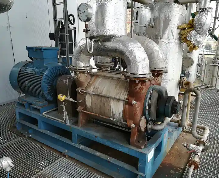
A dry screw vacuum pump is an oil-free positive displacement machine: two meshing screw rotors with conjugate profiles and a controlled gap turn inside a stator, timed by external gears so that no rotor ever touches its mate or the casing. Gas enters at the suction flange, is trapped between screw flutes, transported axially, and compressed as the chamber volume shrinks along the decreasing screw lead, then discharged to atmosphere. Because no oil ever enters the pumping chamber, the exhaust carries process vapor and nothing else, and the process is never contaminated by oil backstreaming. Industry also calls the machine a dry screw pump or an oil free screw vacuum pump. Ultimate pressures run 0.01 to 1 mbar in the standard chemical class, with some designs an order lower, and pumping speeds span roughly 60 to 1,500 m3/h across the family.
Procurement engineers meet these pumps on chemical and pharmaceutical distillation, drying, and evaporation duty, on solvent recovery and degassing, as backing for ejector systems on crude vacuum distillation units, on semiconductor, LED, and photovoltaic coating tools, on transformer evacuation, and on freeze drying lines where ice sublimation loads a condenser and pump pair. The decision this page settles is narrow and practical: whether the duty needs a dry screw at all against the liquid ring, vane, and ejector alternatives, which cooling mode and purge arrangement survive the process gas, what speed the pump must hold at the operating pressure rather than at the catalog ultimate, and what the RFQ must state about dust, condensables, and corrosives. The answer lands as an RFQ line set, and every chapter below feeds that line set.
This page treats the dry screw vacuum pump as a purchasing object: how screw geometry reaches atmospheric discharge with no oil in the chamber, what pumping speed and ultimate pressure numbers actually promise, which cooling, purge, and coating options survive which process gas, and how ATEX, monitoring, and station hardware combine into a defensible RFQ. It is written for engineers who issue purchase specifications, not for readers who want a brochure summary.
Chapter 1 / 06
What a Dry Screw Vacuum Pump Is and What Is Being Decided
The architecture is the product. Two screws with conjugate profiles mesh with a working clearance of a few tenths of a millimetre, held by timing gears and bearings located outside the pumping chamber; the rotors never touch each other or the casing, so there is no metallic contact to lubricate at the point of compression and no wear debris to carry into the process. Gas handling is axial: each flute pair traps a volume at the suction port, conveys it along the screw, and squeezes it as the chamber volume decreases, delivering to the exhaust at atmospheric pressure. Internal clearances of roughly 0.1 to 0.3 mm are the whole sealing story, which is why dust and polymerizing vapors, not old age, are what actually end the service life of these machines.
What is actually being decided in this purchase is a match between a gas and a clearance machine. The buyer commits to pumping speed at the operating pressure, to a cooling mode, to a purge medium and its consumption, to materials and coatings against corrosive species, and to an ATEX category where the area classification demands one. A vacuum pump chosen on ultimate pressure alone will be badly sized, because the process operates far above ultimate. A pump bought without purge against a condensable stream will coke its screws. A pump bought without coatings against acid vapor will pit its rotor profiles. Each of those is a specification decision made in this chapter and priced in chapter 4, and each has a failure story in chapter 6 that a single RFQ line would have prevented.
The neighbor map is worth drawing early, with the full comparison reserved for chapter 5. A liquid ring vacuum pump tolerates condensable loads and rough service at low first cost, but it consumes and contaminates water and stops near 25 to 30 mbar ultimate in wet service. A rotary vane pump is the small package default and seals and lubricates with oil, which backstreams into the process and turns to varnish under solvent load. A roots blower is a booster that stages above any of these for lower pressure and higher speed. The jet pump family contributes the steam ejector, which tolerates the harshest streams in the plant but spends steam continuously. A vacuum generator, the compressed air Venturi, belongs at intermittent workstation duty only, and where the requirement is coarse vacuum at high flow rather than millibar depth, a regenerative blower is the cheaper machine. Two further cousins share the screw name without sharing the duty: the screw compressor works above atmospheric pressure, and the screw pump transports liquid; neither belongs in a vacuum specification, and confusing them in an RFQ produces the wrong quotation every time.
Standards honesty comes early because buyers ask for a product code that does not exist. No single ISO or API product standard governs dry screw vacuum pumps. The industry reference points are PNEUROP guidance on how vacuum pump data is stated, IEC 60034 for the electric motors, the ATEX equipment directive with II 2G T3 or T4 class markings typical of chemical offerings, and CE or UKCA machinery conformity for the package as a whole. Performance claims mean only what the maker's test data behind them means, so an RFQ that demands speed curves at stated inlet pressures and temperatures, with the test basis named, is the strongest specification available in this product class.
The pump never works alone, and the RFQ should name its station. Inlet protection against solids and slugs comes first, because clearances do not forgive debris. Isolation and backspin protection follow at the flange, the discharge path leads to a scrubber or condenser because the exhaust carries the process vapors, the purge supply needs regulation and interlock, and the monitoring instruments read suction pressure and discharge temperature. Each item appears in chapter 4 as a datasheet row and in chapter 6 with its installation rule, and an RFQ that names the whole station buys a system that starts up the first time rather than the third.
Chapter 2 / 06
How the Screws Do the Pumping
Walk the cycle. Gas enters the suction flange and fills the open flutes at the inlet end of each screw. Rotation carries every trapped volume axially along the casing while the screw lead decreases, so the chamber shrinks and the gas pressure rises inside the flute, reaching discharge pressure near the exhaust end and pushing out against atmosphere. There are no valves inside the machine and no sliding contacts in the pumping chamber; the only internal leakage path is back transfer through the working clearances themselves. That back transfer, not joint leakage, is what limits the ultimate pressure, and it is why clean gas discipline and steady casing temperature matter more in this machine than in any oil sealed rival.
Compression heat is the design problem an oil flooded machine solves for free and a dry machine must solve deliberately. An oil flooded vane or screw dumps its compression heat into circulating oil; the dry screw has only its casing, its rotors, and the process gas. In water cooled designs a jacket carries the heat to the water circuit; in air cooled designs fins and a fan do the same to ambient; and in both cases the exhaust stream carries a large share of the heat out with the gas. Where the gas load is hot, dusty, or polymerizing, the cooling decision stops being an accessory choice and becomes the difference between a pump that holds its clearances and one that closes them.
Read the curve at your pressure, not at the brochure corner. A dry screw holds near its full displacement from atmosphere down through the 10 to 100 mbar band, then loses volumetric efficiency as back transfer through the clearances grows, so the speed available at 0.1 mbar is a fraction of the headline displacement. Family sizes span roughly 60 to 1,500 m3/h of displacement, and two pumps of equal displacement can differ materially in deep vacuum speed depending on rotor profile and clearance discipline. The RFQ should demand the speed curve from atmosphere to ultimate at a stated gas and temperature, and the selection should be made at the process operating pressure, with the roots blower staging decision of this chapter kept in reserve for the depths.
Power tracks throughput. Absorbed power rises as gas load rises, peaks in the mid pressure band, and falls again toward ultimate where little gas remains to compress; starting against atmosphere is a real motor duty, and the direct coupled TEFC motors these pumps use are sized for it. Variable frequency drives have become a first class purchasing option rather than a retrofit: on duties with partial vacuum demand, on coating tools that cycle between load and unload, and on processes that spend long periods at low throughput, inverter driven packages of the DWS VSD+ class claim 30 to 60 percent energy savings against fixed speed operation, and they soften the motor start besides.
Purge and gas ballast are the process protection kit, and their discipline is what keeps screws clean. A nitrogen barrier at the shaft seals keeps process vapor out of the bearing and timing gear chambers. A gas ballast or chamber purge port admits nitrogen or dry air into the pumping chamber to dilute corrosive species below dangerous concentrations and to keep condensable vapors from condensing on the screw flutes during compression; steam purge variants serve monomer and solvent duty where deposits form as vapors cool. Purge consumption is a real operating cost, typically a few cubic metres of nitrogen per hour, and it belongs in the RFQ next to the cooling water and power figures rather than in a footnote.
Staging extends the envelope. A roots blower mounted above the dry screw multiplies pumping speed in the 0.01 to 1 mbar band and lets the screw run as a backing pump at a comfortable inlet pressure, which is the standard architecture for large distillation sets and high throughput coating tools. For truly clean processes below that band, other vacuum technologies take over, and the selection chapter draws those lines honestly rather than pretending one screw does everything.
Chapter 3 / 06
Types, Construction, and Duty Boundaries
The twin screw is the market standard and this page's authority. Two parallel rotors with conjugate profiles rotate in opposite directions inside a figure eight casing; makers differ on equal versus unequal screw lead, with unequal lead designs tuning the compression progression along the rotor length and equal lead designs trading some of that control for simpler manufacture and repair. Single screw vacuum machines exist in smaller numbers and share more with hook and claw designs than with the twin screw; a buyer specifying this page's product should write twin screw dry vacuum language into the RFQ and let any single screw offer explain itself on its own merits.
Cooling mode is the first variant decision. Air cooled pumps reject casing heat through fins and a shaft fan or a separate blower, need no water service, and suit clean, modest duty and installations where winterizing water lines is worse than paying a small capacity margin. Water cooled jacket pumps move more heat, hold casing temperature steadier under heavy or dusty gas load, and are the standard choice in chemical service where polymerization and vapor condensation inside the casing must be suppressed. The jacket water is a utility line with its own quality, flow, and freeze protection requirements, and chapter 6 gives it its installation rules.
Materials and coatings are the corrosion decision. Standard construction is ductile or grey iron rotors and casing, correct for air, nitrogen, and most solvent duty. Phosphate, electroless nickel, and PTFE based coatings extend the family to acid vapor and halogen traces; semiconductor duty buys halogen rated variants with special surfaces and clean build protocols; aggressive chloride and HCl service justifies the higher alloy or coated packages some makers build to order. The coating is not decoration: pitting of a rotor profile changes the clearance directly, and clearance change is performance loss that no cheap rebuild recovers.
Shaft sealing separates the pumping chamber from the outside world. The serious standard is a double mechanical seal with a barrier fluid, or a labyrinth with purge where the process allows, and every variant carries a purge connection that keeps process vapor from walking along the shaft into the bearing chamber. The timing gears and bearings live in their own oil bath on the far side of those seals, and that gear oil is the machine's lifeblood: it holds rotor timing, timing holds clearance, and clearance holds performance. A mechanical seal leak is therefore never just an oil drip; it is the leading edge of a contamination problem running in both directions.
The duty boundaries are about the gas, not the pressure. Dry screws earn their price on streams that destroy oil sealed machines: condensable solvent vapor, dust loaded dryer exhaust, corrosive traces, and monomers that would polymerize in an oil sump. They tolerate liquid slugs only in the small, defined quantities the maker's data sheet states, they do not swallow construction debris at all, and their inlet temperature limits are real numbers. The three duties that most reliably kill them are polymerizable vapors without purge discipline, chlorides without coatings, and solids without inlet protection; chapter 6 prices all three. The variant table below consolidates the construction decisions.
Variant
What it changes
Where it is specified
Watch items
Air cooled package
Fins and fan, no water service
Clean modest duty, water scarce sites, small chemical skids
Capacity margin in hot rooms; fan noise contribution
Water cooled jacket
Higher heat rejection, steadier casing temperature
Chemical duty, heavy vapor load, polymerization prone service
Water quality, freeze protection, anti-siphon on shutdown
Coated rotors and casing
Corrosion margin over iron construction
Acid vapor, chloride traces, HCl service
Coating temperature limit; repair and recoat practice
Halogen rated clean build
Clean construction and special surfaces
Semiconductor, LED, and photovoltaic process tools
Gas compatibility list; maker maintenance protocol
Double mechanical seal with barrier
Full isolation of chamber from bearing side
Toxic, flammable, and corrosive processes
Barrier fluid system and its monitoring
Chapter 4 / 06
Key Specification Parameters
The table below decodes the datasheet lines that decide whether a quoted pump matches the duty. Each row is purchase defining; the paragraphs after it explain what to demand and what a weak answer looks like.
Parameter
Typical range
What it decides
Pumping speed, displacement
60 to 1,500 m3/h family sizes
Machine size class, motor rating, and skid footprint
Speed at operating pressure
Near displacement at 10 to 100 mbar, a fraction at 0.1 mbar
Whether the process duty point is genuinely covered
Ultimate pressure
0.01 to 1 mbar class, lower on some designs
The floor of the specification, rarely the working point
Inlet and outlet bore
DN 40 to DN 200 class by size
Station piping, valve, and protection hardware sizing
Motor and drive
Direct coupled TEFC, fixed speed or VFD packages
Energy behavior, start duty, and control philosophy
Cooling
Air fan, or water jacket with stated flow
Utility list and behavior under hot and dusty gas load
Purge consumption
A few m3/h nitrogen class, stated per connection
Operating cost and site nitrogen availability
Discharge temperature trip
110 to 130 deg C class set point
Protection against coking and seal damage
Noise
Mid 60s to mid 70s dB(A) class
Operator exposure and analyzer room siting
ATEX marking
II 2G T3 or T4 class typical for chemical zones
Zone acceptance and certification package
Weight and envelope
Hundreds of kg to tonnes by size
Floor loading, lifting plan, and maintenance access
The gas analysis is the real specification, and no row of the table substitutes for it. Dust loading in grams per hour, condensable load in kilograms per hour, and the corrosive species named by compound decide inlet protection, purge rates, coatings, and cooling mode. A quotation written against a fluid description that says only vacuum, 5 mbar is a price tag, not a design. Where the stream carries polymerizable monomers, the RFQ should say so in those words, because the vendor's purge protocol and solvent flush schedule are the countermeasures, and they are purchased line items, not favors granted at startup.
Monitoring is inexpensive and predictive, and it belongs on the datasheet with tag numbers. A temperature transmitter or RTD at the gas discharge, tripping in the 110 to 130 deg C class, is the primary machine protection, because discharge temperature is the earliest honest signal of coke build up or clearance loss. A vacuum gauge at the inlet, Pirani or capacitance class, trends performance against the commissioning baseline. A pressure transmitter on the discharge path or the seal barrier watches the exhaust system and the seal fluid, and motor current rounds out the picture. Retrofit wiring onto a running pump is the expensive way to buy all four.
The station hardware table below lists what surrounds the pump in a defensible installation; chapter 6 attaches the installation rules to each row.
The decision sequence below runs as a checklist in a specification meeting, and each step eliminates a class of quotations before any price comparison starts.
State the operating pressure and the pumping speed required at that pressure, with the gas composition, not the ultimate pressure alone.
Quantify the difficult loads: dust in grams per hour, condensables in kilograms per hour, corrosive species by name, and polymerizable monomers named as such.
Choose cooling against the gas: air cooled for clean modest duty, water jacket for heavy, dusty, or polymerization prone service.
Choose purge: nitrogen barrier at the seals, chamber purge or gas ballast for condensables and corrosives, steam purge for monomer duty, and confirm site nitrogen availability.
Choose materials and coatings against the corrosives, and write the ATEX category with certificate requirement where the zone demands it.
Stage where depth matters: a roots blower above the screw for speed below about 1 mbar, with the screw confirmed as the backing machine.
List the station: inlet protection, isolation, backspin protection, discharge treatment, purge regulation, cooling services, and monitoring.
Fix the evidence: speed curve from atmosphere to ultimate at stated conditions with test basis, noise data, ATEX certificate, and IEC 60034 motor conformity.
Against the neighboring technologies, the honest comparison runs as follows, and it belongs here in the selection chapter rather than in the page title. The liquid ring vacuum pump is cheaper, nearly indestructible, and glad to swallow condensable loads, but it consumes and treats water, its wet ultimate sits near 25 to 30 mbar, and contact between process and sealing fluid is a contamination liability on solvent duty. The rotary vane pump wins small packages on price and holds a lower ultimate, but its oil seals, lubricates, and backstreams, and solvent and dust loads turn that oil into varnish and sludge. A roots blower stages above either machine rather than replacing one. The steam ejector branch of the jet pump family tolerates the harshest, hottest streams at the price of continuous steam and water utilities. A vacuum generator, the compressed air Venturi, is right only for intermittent spot duty where shop air is cheaper than a pump. A regenerative blower covers coarse vacuum at high flow where millibar depth is not needed at all. The naming trap repeats at the top of the pressure scale: a screw compressor is the same rotor geometry pointed above atmospheric pressure, sold into compressed air and process gas duty, and it never belongs on a vacuum line except by clerical error. For the duty between those stools, dirty, condensable, corrosive, or monomer laden gas at 0.1 to 10 mbar with an oil free exhaust, the dry screw vacuum pump is the machine that needs none of the others' excuses.
The application map below turns that comparison into a table the project file can carry.
Application
Construction to specify
Check before order
Chemical and pharma distillation, evaporation
Water cooled jacket, coated rotors where corrosive, N2 purge, roots blower above for depth
Gas compatibility list; cycle energy between load and unload
Transformer evacuation
Standard build, air or water cooled, single stage sufficient
Moisture load; hold pressure verification test
Freeze drying line
Paired with condenser, VFD or two speed for phase control
Ice sublimation load split between condenser and pump
Crude vacuum distillation ejector backing
Heavy duty water cooled, corrosion coated as the gas requires
Backing pressure tolerance; continuous rating; sour service materials
Solvent recovery
Water cooled with chilled discharge condenser
Recovery efficiency versus purge rate; emission rules
The RFQ block should be written once and reused. A complete block reads: pumping speed required at the operating pressure, with that pressure stated; ultimate pressure requirement; process gas composition with dust, condensable, corrosive, and monomer loads quantified; cooling mode with utility figures, water flow or air; purge medium, connection size, and consumption; materials and coatings; ATEX category with certificate reference where applicable; inlet and outlet bore; noise at the operating point; drive type with the VFD requirement where partial demand is expected; the station hardware listed by name, inlet knockout pot or Y strainer, isolation ball valve, backspin check valve, discharge condenser or scrubber, purge regulator and solenoid valve; monitoring with inlet vacuum gauge, discharge temperature transmitter or RTD trip, pressure transmitter, and motor current; and the evidence, the speed curve at stated conditions, its test basis, and motor conformity to IEC 60034. A quotation returned without the speed at your operating pressure is incomplete at any price.
Chapter 6 / 06
Installation, Standards, Failure Modes, and Maintenance
Installation quality decides whether the clearances see their design life. Protect the inlet first: a knockout pot or Y strainer stops scale, catalyst fines, and polymer chips that a 0.1 to 0.3 mm clearance cannot survive, and an isolation ball valve at the flange allows lockout for the work that follows. Backspin protection comes next, a check valve at the inlet or an automatic vent arrangement, because atmospheric pressure drives a stopped screw set backward and the timing gears pay for it. Route the discharge to a condenser or scrubber sized for the vapor load, since the exhaust carries the process vapors in transport form. Give the purge line its regulator and solenoid valve, interlocked so nitrogen flows before the process does and after it stops. On water cooled units fit flow indication and an anti-siphon arrangement so the jacket cannot drain by gravity when the pump is off, and protect the line against freezing where the site has a winter.
Commissioning writes the baseline the machine is judged against for the rest of its life. Prove the purge and cooling services before the motor turns; confirm rotation; run the pump against a closed inlet to record the blank off pressure the clearances actually achieve; then admit process and record the inlet vacuum gauge reading, the discharge temperature, and the motor current at the normal operating point. File those numbers with the speed curve and the trip settings. The discharge temperature transmitter alarm at its set point, the inlet gauge baseline, and the current signature are the three trends that will later separate a dirty inlet from a coking screw from a failing bearing without arguments.
The standards frame closes honestly. No single ISO or API product code governs the dry screw vacuum pump; the reference points are PNEUROP industry guidance for how vacuum pump data is stated, IEC 60034 for the motor, the ATEX equipment directive with II 2G T3 or T4 class markings typical for chemical zones, and CE or UKCA machinery conformity for the package. What the standards do not fix, the purchase document must: the speed curve basis with its test gas and temperature, the noise measurement position, the purge protocol, and the acceptance values at commissioning. Those four lines, written by the buyer, are what make two quotations comparable in this product class.
Failure modes in service follow a short and predictable list. Polymerization and coking lead it: process vapors condense and bake onto the screw flutes, absorbed torque rises gradually, and the machine trips or seizes; the countermeasures are purge discipline, solvent flush protocols, and discharge temperature trending that catches the rise months early. Corrosion pitting of rotor profiles follows acid vapor service without coatings, and it appears as speed curve shift long before anything visible. Bearing and timing gear wear shows as noise, then as timing error and rotor contact; the gear oil change on the roughly 8,000 hour schedule is the prevention. A mechanical seal leak on a double seal installation loses barrier fluid first and process containment second. Dust overload wears the clearances open, the blank off pressure rises, and the repair is a shop job, re-shimming or screw replacement, not a field adjustment.
Maintenance intervals scale with gas severity. Yearly: gear oil change on the 8,000 hour class schedule, motor bearing greasing, seal barrier fluid checks, and a visual through the inlet for deposit color and quantity. Every 12 to 24 months depending on the stream: internal screw inspection, cleaning, and clearance verification against the maker's data. Overhaul class is 40,000 hours on clean duty and materially less on monomer and dust service, and the spares list should say so in exactly those terms. Every check writes one line into the machine record, and that record is what converts the next RFQ from a guess into a specification written from measured life.
FAQ
What ultimate pressure can a dry screw vacuum pump actually reach?
Standard chemical class machines reach 0.01 to 1 mbar ultimate, and some designs reach about an order lower under favorable conditions. Ultimate is the blanked off floor, not the working point: available speed falls as pressure falls, so select on the speed curve at your operating pressure. Where a process needs sustained pumping below the 0.01 mbar class, the answer is staging with a roots blower or a different technology, not a larger screw.
Dry screw or liquid ring for chemical duty?
Choose the dry screw when the exhaust must stay oil free and process clean, when water consumption or sealing fluid contamination is a problem, and when the duty sits below the 25 to 30 mbar wet ultimate of the ring machine. Choose the liquid ring vacuum pump when the gas is extremely condensable or dirty, water is cheap, and the ultimate pressure requirement is modest. On deep distillation duty the two often appear staged together behind a booster.
Why does the pump need nitrogen purge?
Purge does three jobs. It keeps process vapor out of the bearing and timing gear chambers through the shaft seals, it dilutes corrosive and condensable species inside the pumping chamber so they neither condense on the screws nor attack them, and on shutdown it sweeps the machine clean of process gas before that gas can cool and deposit. Nitrogen at a few cubic metres per hour is typical, and the connection and its interlock belong on the datasheet.
Air cooled or water cooled jacket?
Air cooled packages need no water service and suit clean, modest duty and sites where winterizing water lines is a burden. Water cooled jackets move more heat and hold casing temperature steadier under heavy, dusty, or polymerization prone gas load, which is why they are the standard chemical choice. Decide by the gas, not by utility preference: a hot condensable stream on an air cooled body is a coke recipe.
Can it handle dust and polymerizing vapors?
Yes, with protection, and that is precisely the duty class that justifies the machine over oil sealed rivals. Solids need a knockout pot or strainer at the inlet, because clearances of 0.1 to 0.3 mm do not forgive swarf and fines. Polymerizable monomers need purge discipline and a solvent flush schedule, with discharge temperature trended as the early warning: a gradual torque and temperature rise is the signature of coke building on the flutes.
What protection belongs at the pump inlet and discharge?
At the inlet: a knockout pot or Y strainer against solids, an isolation ball valve for lockout, and a check valve or auto vent to prevent backspin on shutdown. At the discharge: a condenser or scrubber sized for the vapor load, because the exhaust carries the process vapors in transport form. Purge regulation with a solenoid valve completes the station and is interlocked to the process sequence.
What maintenance does a dry screw vacuum pump need?
Plan a gear oil change on the roughly 8,000 hour schedule, yearly motor bearing greasing and barrier fluid checks, and an internal screw inspection every 12 to 24 months depending on the gas. Overhaul class is 40,000 hours on clean duty and less on monomer or dust service. The discharge temperature trend against the commissioning baseline is the single most valuable early warning the operator has.