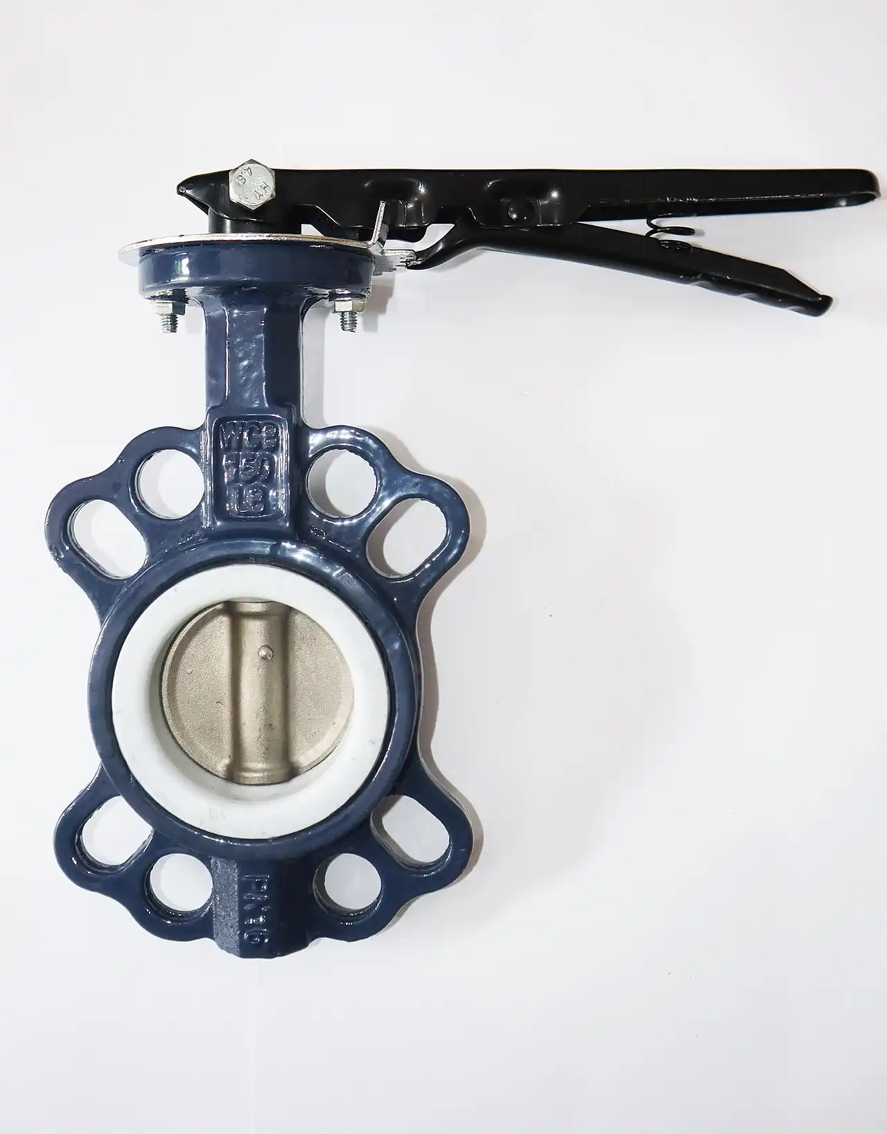
A wafer butterfly valve is a quarter-turn rotary valve whose disc, seat, and stem sit inside a thin center body that has no integral flanges. The valve is clamped between two pipeline flanges, and the bolting that pulls those flanges together passes through or around the wafer body to hold it in the line. The style exists because a large percentage of industrial isolation and rough-throttling duties do not need the metal thickness, weight, or cost of a flanged or lug body, and because a short face-to-face simplifies compact skid and manifold layouts.
Procurement engineers meet the wafer style in water distribution, HVAC chilled and condenser water, compressed air, fire protection mains, treatment plant headers, and low-pressure utility chemical lines. Sizes run from DN 50 to well past DN 1200, with CL150 the dominant pressure class and resilient seated construction the dominant seal technology. The decision that actually lands on a buyer is narrower than "which valve": it is whether the line can be taken depressurized and drained for valve removal, because a wafer body falls out of the pipeline the moment the flange spread begins. That single fact separates the wafer body from the lug butterfly valve and drives most of the specification language on this page.
This page decodes the wafer butterfly valve as a purchasing object: what the body style does and does not support, how API 609 categories and ISO 5752 face-to-face dimensions appear on datasheets, which seat and trim combinations survive which fluids, and how torque, differential pressure, and installation practice interact. It is written for engineers who must write a defensible RFQ, not for readers who want a marketing summary.
Chapter 1 / 06
What a Wafer Body Is and What Is Being Decided
The defining feature of a wafer butterfly valve is structural, not hydrodynamic. A gate valve or globe valve carries its pressure boundary in a body with integral end flanges or welded ends; the bolts that seal the joint thread into the valve itself or clamp a gasket against a machined face. A wafer body has none of that. It is a machined ring, typically 25 to 130 mm long across the full size range, with an elastomer or polymer seat molded or cartridge-loaded into its bore, a disc on a shaft or two shafts, and a set of bolt holes or external ears designed only to register the body between the pipeline flanges. The line pressure that the valve controls is contained by the pipeline flanges and their gaskets, not by the valve ends.
What is being decided when a wafer style is specified is therefore three commitments at once. First, a commitment to line bolting: the installer must have access to both flanges, and the flange bolt lengths must account for the wafer body thickness plus two gaskets. Second, a commitment to shutdown practice: because the body carries no lug holes that tie the two pipeline flanges to each other through the valve, removing the valve requires spreading the flanges, which means the downstream side of the line must be drained or isolated by other equipment. Third, a commitment to dead-end limits: several seat designs rely on the pipeline flanges to back the seat, and a wafer valve installed at the open end of a line, or blind flanged on one side only, may blow out or leak because nothing restrains the seat insert axially.
The comparison that frames every wafer specification is the lug butterfly valve. The lug body has threaded or through-drilled bosses at each bolt position, so the installer can bolt the valve to one flange while the other side of the line remains pressurized, and can remove the downstream piping with the upstream side held by the valve alone. That convenience costs money and weight, and it is wasted money on lines that are routinely drained anyway. Conversely, specifying a wafer body to save cost on a line that must remain live during maintenance is the single most common wafer specification error, and it surfaces as a change order rather than as a calculation, usually after installation. A check valve upstream does not remove the constraint, and neither does a Y strainer; only positive isolation of both sides does.
Engineers also meet the wafer body in the language of API 609, the standard that most datasheets reference for butterfly valve categories. API 609 Category A covers resilient seated valves with leakage rates far below shutoff class expectations of metal designs, while Category B covers offset-seat metal or lined designs rated for higher pressure and temperature. Most wafer bodies purchased for water and utility service are Category A concentric designs; the double and triple offset high-performance butterflies that dominate steam and hydrocarbon service are usually lug or flanged bodies, although offset wafer patterns exist. Understanding which category a supplier is quoting prevents the classic mismatch where a buyer expects Category A resilient sealing on a Category B seat or the reverse.
Finally, the wafer decision interacts with the rest of a piping package. A typical water side scheme includes a centrifugal pump, a suction isolating valve, a discharge check valve, and a throttling or isolating valve downstream; wafer butterflies are candidates for the suction and discharge isolation duties, not for the check function. In treated water headers they sit beside knife gate valve and wedge gate valve installations at larger diameters, where the butterfly wins on weight, length, and actuator torque. The RFQ language should state the neighboring equipment explicitly so the supplier can confirm gasket, flange drilling, and face-to-face compatibility in one pass.
Chapter 2 / 06
How a Wafer Butterfly Valve Seals and Operates
Sealing in a resilient wafer butterfly valve is achieved by interference. The seat, an elastomer ring of EPDM, NBR, or a fluoropolymer depending on the fluid, is molded into the body bore with an inner diameter smaller than the disc diameter. When the disc rotates to the closed position, its edge wedges into the seat, elastically deforming the rubber until the contact stress along the disc edge exceeds the line differential pressure multiplied by the exposed area. The seat is loaded in the factory; the field does not adjust it. This is why resilient butterfly valves reach their best leakage class when new and why repeated operation at high differential pressure slowly engraves a seat mark.
The torque curve of a butterfly valve is not flat, and the number a buyer needs is not a single value. Breakaway torque at the seat, the moment needed to unseat a closed disc after dwell, commonly runs 1.2 to 2.5 times the running torque at mid travel, and it grows with seat age, fluid temperature cycles, and line sediment. Hydrodynamic torque, produced by flow acting on an off-center disc, peaks near 60 to 75 degrees open in many designs and can oppose or assist the actuator depending on flow direction. A gear operator or a pneumatic valve actuator sized only on running torque will stall on breakaway; sizing on breakaway alone wastes money on oversized actuators. Datasheets that publish only one torque figure without stating the travel position and differential pressure should be challenged in the RFQ.
Flow capacity is the second quantitative axis. Resilient wafer butterflies have flow coefficients roughly comparable to a full-bore gate valve of the same size at full open, with Cv values from about 60 at DN 50 to well above 20,000 at DN 600, expressed in US units, with the equivalent Kv about 12 percent lower numerically. In the partially open range the butterfly is a percentage-to-linear characteristic device: 30 degrees open may pass only 10 to 20 percent of full flow, while 60 degrees may pass 60 to 75 percent. For modulating duty this matters more than the rating at full open, because the control loop spends its life in the 20 to 60 degree band where disc position maps steeply onto flow. A control valve or a dedicated globe valve remains the better choice when precise low-flow control is required; the wafer butterfly wins where the duty is two-position or rough throttling.
The wafer body changes the mechanical load path compared with flanged construction. With the disc closed and differential pressure applied, the hydraulic force on the disc is carried into the body through the shafts and bearings, while the body itself is clamped between pipeline flanges and loaded by the bolt compression. The gaskets on each side are compressed by the same bolts. Under- or over-tightening the flange bolts therefore does two kinds of harm: under-torque leaks at the joints and lets the body shift, over-torque crushes the seat O-ring land or distorts thin wafer bodies, especially in ductile iron at large diameters. Suppliers publish bolt torque tables by size and gasket type, and those tables are part of the purchase package, not an installation afterthought.
Cavitation and choke flow set the hydraulic ceiling. When a butterfly throttles a high head drop, the vena contracta pressure downstream of the disc edge can fall below the vapor pressure of the liquid, and the collapsing vapor bubbles hammer the disc edge and the adjacent seat. Signs are noise above 85 dB near the valve, pitting on the leading disc edge within months, and seat failure that looks like chemical attack but is not. The standard defenses are to limit the throttling pressure drop per valve by staging two valves, to choose a disc with a hardened or staggered edge at the same base cost from many suppliers, or to relocate the throttling duty to a valve built for recovery service. On water with 6 bar upstream and atmospheric downstream, a single resilient wafer butterfly at half travel will cavitate; the same service with a downstream butterfly sharing the drop will usually not.
Chapter 3 / 06
Types, Construction, and Duty Boundaries
Wafer butterflies divide first by seat architecture. The concentric resilient seat, in which the disc rotates about an axis through the seat center and squeezes a continuous rubber ring, is the volume product; it spans about DN 40 to DN 2000 in special constructions, with CL150 and CL300 drillings available although most volume is CL150. The high-performance double offset wafer uses a disc that lifts off the seat immediately on opening, reducing seat wipe and wear, and positions the seat as a discrete PTFE or metal ring loaded by springs; these exist in wafer pattern to about DN 600 typically. Triple offset designs, with their conical metal seat geometry and torque seated lamellar rings, are mostly lug or flanged, but wafer versions serve compact skids in oil and gas to DN 400 and beyond.
Materials set the fluid envelope. Body castings in ductile iron A536 65-45-12 dominate water and HVAC; WCB carbon steel bodies carry higher temperature and satisfy code cases where iron is excluded; CF8M stainless steel bodies serve demineralized water, food rinse, and coastal corrosion atmospheres, and duplex 2205 bodies appear in seawater and high chloride duties where CF8M would pit. Discs range from ductile iron with EPDM or nylon coating, through CF8M and 17-4 PH stainless, to aluminum bronze for seawater. Shafts are usually 416, 420, or 17-4 PH stainless in resilient valves and monel or duplex in offshore metal-seated service. Seat compounds divide cleanly: EPDM for water, steam to about 120 deg C and weather; NBR for oils, fuels, and compressed air; fluoropolymer and perfluoroelastomer seats for chemicals and temperatures from about minus 20 to 200 deg C depending on compound.
Pressure and temperature boundaries are asymmetric in a way that surprises first-time buyers. A DN 100 wafer butterfly may be rated 16 bar at 20 deg C and only 5 bar at 120 deg C on an EPDM seat, and the derate curve is seat compound specific. Vacuum service is a separate check, because an outside-in pressure differential can lift the seat land away from the body groove in designs where the seat is retained by line flange compression; most manufacturers state a partial vacuum limit or require a vacuum-rated seat profile. Dead-end service, closing against pressure with only one pipeline flange downstream or with a blind flange directly after the valve, is prohibited by several major manufacturers outright and allowed by others only with a specific seat design; API 609 text and manufacturer manuals both address it, and the RFQ must state the dead-end intent explicitly.
Duty boundaries by neighboring function are equally concrete. A wafer butterfly is not a safety device: it does not substitute for a safety relief valve, it has no fire-safe qualification unless specifically built and tested to API 607, and its failure position is whatever the operator or return spring makes it. It is not a check valve; reverse flow slams the disc and can crush a resilient seat. It is a poor choice for slurries with settling solids because the lower seat line packs with sediment, where a knife gate valve or a diaphragm valve design handles the same duty better. And it cannot be buried or jacketed in wafer pattern with the same ease as flanged bodies, because the clamp load path depends on accessible flange bolts.
End compatibility closes the construction question. Wafer bodies are drilled to match ASME B16.1 CL125, B16.5 CL150, EN 1092-2 PN10/16, or JIS 10K patterns, and the same body casting is often machinable for several of these; ordering the wrong drilling is the most common receiving reject. Face-to-face follows ISO 5752 short series for most manufacturers, with API 609 and AWWA C504 (longer, for water works flanged drilling) as alternates; a wafer face-to-face is short enough that replacing an installed gate valve of the same nominal size usually requires a spool piece, while replacing another butterfly is a drop-in. Gaskets are usually flat sheet or segmented, full face on flat-face flanges and ring type on raised face flanges only when the wafer body carries a raised sealing land, which most resilient designs do not.
The duty map below consolidates the boundaries into one table a specifier can scan before writing the RFQ; it pairs each common service with the construction that survives it and the construction that causes callbacks.
Service
Suitable wafer construction
Construction to avoid
Potable and HVAC water, 5 to 16 bar, 5 to 60 deg C
Ductile iron body, EPDM seat, coated DI or CF8M disc
NBR seat (swells slightly, shortens life)
Compressed air, 7 to 10 bar
Ductile iron, NBR seat, metal disc
EPDM seat with oil carryover from lubricated compressors
Diesel and fuel oil transfer
Ductile iron, NBR or fluoropolymer seat
EPDM seat, painted disc without compatibility certificate
Treated effluent with soft solids
Ductile iron, EPDM seat, 17-4 PH shaft
Concentric seat with lower wipe land that packs with sediment
Settling slurry, high solids
Not a wafer butterfly duty; use knife gate valve or diaphragm designs
Any resilient concentric wafer (seat engraves within weeks)
Coastal or deicing salt water
CF8M or duplex 2205 body and disc, EPDM seat
Coated ductile iron disc, 416 shaft (pits at crevices)
Closed loop glycol, up to 120 deg C
Ductile iron, EPDM seat, derate curve verified
Class stamped pressure assumed flat to 120 deg C without derate table
Line end isolation against full pressure
Dead-end rated seat per manufacturer statement
Standard wafer seat relying on downstream flange retention
Chapter 4 / 06
Key Specification Parameters
The table below decodes the datasheet lines that decide whether a quoted wafer butterfly valve matches the service. Each row is a purchase-defining parameter; the paragraphs after the table explain what to demand and what a weak answer looks like.
Attribute
Typical range or options
What it decides
Nominal size
DN 40 to DN 1200 (CL150 volume range DN 50 to DN 600)
Pipe schedule, flange drilling, face-to-face length, and torque class of the operator
Pressure class
PN10/16, CL125/150; CL300 in offset designs
Body rating, test pressure, and the temperature derate curve applied to the seat
API 609 category
Category A resilient or Category B offset
Leakage expectation, seat type, and whether the valve is a utility or high-performance item
Seat compound
EPDM, NBR, PTFE, perfluoroelastomer
Fluid compatibility, temperature limits from about minus 40 to 230 deg C, and vacuum behavior
Body material
Ductile iron, WCB, CF8M, duplex 2205
Corrosion envelope, code acceptance, and weight of the installed package
Disc and shaft
Coated DI, CF8M, 17-4 PH, aluminum bronze
Wear life in throttling, seawater acceptability, and stem shear strength
Face-to-face
ISO 5752 short series; API 609; AWWA C504
Drop-in replacement geometry and spool piece need
Shutoff class
API 609 Category A: zero visible leak; Category B per class VI or class IV analog
Acceptance test applied at the seat during factory testing
Flow coefficient
Cv 60 at DN 50 to above 20,000 at DN 600
Full-open pressure loss and the throttling characteristic in the 20 to 60 degree band
Operating torque
Breakaway 1.2 to 2.5 x running torque
Lever, gear, or actuator sizing; missed breakaway data is a reject flag
Pressure class deserves one more sentence than the table carries: the class stamped on a wafer body is the class of the drilling and the body test, not a flat service rating. The usable pressure is the lower of the body rating and the seat derate at temperature, and on EPDM the seat usually governs above 80 deg C. Buyers replacing an old iron valve with a "same class" wafer should ask for the derate table explicitly, because two manufacturers with identical catalogs on the front page can differ by 30 percent in allowed pressure at 110 deg C.
Torque and actuator rows link this page to the operator decision. A wafer butterfly with a bare stem accepts a lever to about DN 150, a worm gear to about DN 300 depending on pressure, and an actuator above that or anywhere remote operation or fast cycling is needed. The pneumatic valve actuator path scotch yoke or rack and pinion is specified on breakaway torque with a safety factor, commonly 1.25 to 1.5, at the worst credible differential; an electric actuator is chosen on the same number plus a duty cycle statement. Where shutdown behavior matters, the RFQ must state the desired fail position, because spring return doubles the actuator envelope and changes the torque budget in the closing direction.
Shutoff class language ties back to API 609. Category A valves are tested for essentially zero visible leakage at the seat; Category B valves carry an assigned class with allowable rates. Neither category says anything about stem leakage class unless ISO 15848 or an equivalent fugitive emission requirement is written in; on water and air service most buyers omit it, while on chemical service it should appear. The buyer who writes "API 609" alone has not fully specified leakage; writing "API 609 Category A, seat and shell tested to ISO 5208 rates A and B respectively" closes the loop.
Two rows in the table are ordering traps. Flange drilling and face-to-face must both match the installed flanges, and the two are independent: a PN16 drilling on a CL125 flat face will bolt up loosely or not at all, and an ISO 5752 long-pattern valve substituted for a short one shifts the piping by tens of millimeters at exactly the wrong moment on a retrofit. The second trap is the Cv line: manufacturers publish Cv at full open, but the number that sizes a throttling station is the installed characteristic, and a supplier who cannot provide Cv versus angle data for at least 15, 30, 45, 60, and 90 degrees is not supporting a throttling application properly.
Chapter 5 / 06
Selection Decision Factors and RFQ Language
The decision sequence for a wafer butterfly valve is short enough to run as a checklist in a specification meeting, and each step eliminates a class of quotations before price comparisons begin.
Confirm the removal scenario: can both sides of the line be drained and depressurized when the valve must come out? If no, stop and specify a lug butterfly valve instead of a wafer body.
Confirm the dead-end scenario: will the valve ever hold pressure with an open or blind-flanged downstream side? If yes, write it into the RFQ and require a manufacturer statement of dead-end capability.
Fix the fluid and temperature envelope, including cleaning and sterilization cycles if any, and select the seat compound from it; EPDM for water and weather, NBR for oil and air, fluoropolymer for chemistry and heat.
Fix the body, disc, and shaft materials against corrosion code requirements and chloride content; upgrade to CF8M or duplex 2205 before coastal or deicing salt exposure, not after the first disc pits.
Set the shutoff requirement in words: API 609 Category A resilient for near zero leakage, Category B offset where pressure or temperature pushes past resilient limits.
Compute the torque envelope at maximum differential and add the safety factor; select lever, gear, or actuator and state the fail position and any positioner requirement.
Verify flange drilling, facing, and face-to-face against installed flanges and ISO 5752 or project standard; order gaskets in the same package.
Write the RFQ with fluid, limits, counts, and the verification evidence required: derate curves, torque data, Cv versus angle, and test certificates.
Cost behavior follows the torque curve more than the price list. The table below shows representative budget ranges for one DN 100 duty in three material and operator combinations; the numbers are planning figures for budgeting, not quotations, and they move with market metal prices and order volume.
Configuration (DN 100, CL150)
Body and seat
Operator
Budget range USD
Utility water isolation
Ductile iron, EPDM seat, coated disc
Lever
90 to 220
Utility water isolation
Ductile iron, EPDM seat, coated disc
Worm gear
180 to 380
Treated water, stainless contact
CF8M body, EPDM seat, CF8M disc
Worm gear
350 to 700
Compressed air or oil line
Ductile iron, NBR seat, coated disc
Lever
100 to 250
Remote automated isolation
Ductile iron, EPDM seat
Double acting rack and pinion actuator
450 to 900
High chloride coastal duty
Duplex 2205 body and disc, EPDM seat
Worm gear
1,400 to 2,600
The RFQ block for a wafer butterfly valve should be written once and reused. A complete block reads: quantity and size; flange standard, class, and facing; face-to-face standard; API 609 category and required seat test; fluid, concentration, and solids; minimum and maximum temperature with cycles; maximum steady differential and transient; seat, body, disc, and shaft materials; operator type with fail action and accessory list, including solenoid and limit switch voltages; dead-end and vacuum statements; certificates required, typically ISO 5208 seat test, material certificates EN 10204 3.1, and paint specification; and the drawing package expectation: external dimensions, torque curve, Cv versus angle, and the pressure temperature derate table. A quotation returned without the derate table or the torque curve is incomplete regardless of price.
Two neighbors in the piping scheme deserve explicit lines in the RFQ rather than assumptions. Where the scheme pairs the wafer butterfly with a ball valve upstream for double isolation, state both valves so the suppliers confirm face-to-face and drilling compatibility across the pair. If the scheme includes a strainer upstream, state its type and clearances, because a Y strainer with coarse mesh protects the wafer seat from weld bead and scale during commissioning at trivial cost. If the scheme pairs the valve with a pump, state the pump type and shutoff head, because a centrifugal pump can deliver shutoff pressure above nominal line pressure and the butterfly derate is evaluated at the credible maximum, not the average. Both lines convert an argument at startup into a checked box at order review.
Chapter 6 / 06
Installation, Standards, Failure Modes, and Maintenance
Installation quality decides whether a wafer butterfly valve reaches its catalog life. The body must be centered between the flanges with the disc slightly open during mounting so the disc edge does not cut the seat on insertion; most manufacturers specify 10 degrees open at fit-up. Gaskets seat on the flange faces, not on the valve body, and must be holed to clear the seat land. Bolts are brought up in a cross pattern in at least three passes to the supplier torque table, because the clamp load that seals the joints is also the load that keeps the wafer body registered; a body installed off center by more than a millimeter or two will show early seat leakage on one side. Pipework alignment tolerances, quoted by most manufacturers as a few millimeters of offset and gap across the joint, apply before the valve is offered up, not corrected by pulling the flanges together with bolts.
Commissioning practice protects the seat from its first week of service. Flushing the line before first closure keeps weld spatter and gasket cuttings out of the seat; a first closure against full differential pressure on a dirty line can engrave debris into the elastomer permanently. The lever or gear travel stops are set at the factory, but the installer verifies that 90 degrees open aligns with the position indicator, and on geared units the closing stop is rechecked after the first pressure cycle. On automated valves, the stroke is set on the actuator with the valve in the line, and the torque switch or current limit on an electric quarter-turn unit is set from the measured running torque plus margin, never from a generic default.
The standards set the verification frame. API 609 defines the categories, design examination, and pressure testing referenced throughout this page. ISO 5752 fixes face-to-face and center-to-face dimensions so a short-pattern valve is interchangeable between makers. ISO 5208 defines the pressure test rates cited on certificates. AWWA C504 governs the longer water works butterflies with their own drilling and coating expectations. For fire risk installations, API 607 qualification is the fire test reference, and it must be asked for explicitly; a standard resilient wafer valve does not carry it. Where fugitive emissions matter, ISO 15848 stem testing replaces the default stem packing acceptance, which on most resilient designs is simply "no visible leak" during factory shell test.
Failure modes in service follow a predictable short list. Seat imprint: after hundreds of cycles or years of static closure, the disc edge wears a groove in the elastomer, and leakage appears first at low differential; the fix is seat or seat-cartridge replacement, which on cartridge designs is a workshop job measured in hours. Seat swelling and hardening: chemical incompatibility or heat aging changes seat volume and torque; a breakaway torque that doubles over two years is a seat replacement trigger, and writing a torque measurement into the annual check catches it. Stem leakage: packing adjustment on accessible designs, or shaft seal kit replacement; persistent weeping on a water service valve is tolerable for weeks, on chemical service it is not. Disc edge erosion and cavitation pitting: covered in chapter 2, remedied by staging pressure drops or hardfacing the disc on replacement. Body corrosion: coating damage at the flange faces on buried or Immersed duty; wafer bodies in soil require wrap systems and are usually avoided in favor of flanged patterns for buried service.
Maintenance intervals scale with duty. A isolation valve cycled twice a year on clean water needs an annual exercise to mid travel, a check of flange bolts for relaxation after the first year, and a seat replacement plan based on leakage observation rather than calendar. A throttling valve in continuous service deserves quarterly checks of disc position versus command, torque trend where an actuator reports it, and an internal inspection at the first major shutdown after three years. Automated packages add the instrument layer: solenoid valves, limit switches, and positioners verified on the same schedule as the rest of the control loop, and on spring return units the spring side is checked for corrosion wherever the environment is wet. Every one of these checks is cheaper than an unplanned drain-down of the line, which for a wafer installation is the recurring reminder of the body style decision made at order time.
FAQ
Can a wafer butterfly valve be used at the end of a line against pressure?
Only if the manufacturer explicitly rates that dead-end service. Many resilient wafer designs rely on the downstream pipeline flange to retain the seat axially, so closing against a blind or open end can eject the seat or deform the body land. API 609 Category A datasheets often exclude dead-end duty by note. If the layout needs a line-end valve, specify a dead-end capable seat design in the RFQ or move to a lug or flanged body.
How do I know whether to order wafer or lug bodies for the same service?
Decide on maintenance practice, not on price. If the line will be drained and depressurized whenever the valve is removed, the wafer body is correct and lighter. If one side must stay live during removal, the lug body with threaded or through-bolt lugs is mandatory because the pipeline flanges stay tied through the valve. The cost gap is typically 25 to 60 percent at DN 100, which is small compared with one unplanned shutdown.
What seat material should I specify for mixed water and oil traces?
NBR handles oils and tolerates water but weathers poorly outdoors; EPDM is superior for water and steam up to about 120 deg C but swells in hydrocarbons. With genuine mixed duty, choose a fluoropolymer or perfluoroelastomer seat and pay the premium, because the common compromise of EPDM with occasional oil contact fails by swelling within months. State both fluids with concentrations in the RFQ and let suppliers propose the compound.
Why did my actuator stall on a valve that met the torque figure in the catalog?
Most stall cases come from breakaway torque after dwell, which runs 1.2 to 2.5 times running torque, or from a differential pressure higher than the sizing assumption, often pump shutoff head. Verify the actuator was sized on breakaway at maximum credible differential with a 1.25 to 1.5 safety factor, and ask the valve supplier for the torque curve rather than a single number. Aged or sediment loaded seats also raise breakaway torque over time.
Do wafer butterfly valves meet fire-safe requirements by default?
No. Standard resilient seated wafer valves lose their soft seat in a fire. Fire safe service requires a design tested and qualified to API 607 or ISO 10497, usually a metal or firesafe-lined seat construction, and the qualification must be stated and evidenced in the quotation. Ordering API 609 Category A alone does not provide any fire qualification.
What pressure does the valve actually hold at 100 deg C?
Not the class stamped on the body. The usable rating is the lower of the body rating and the seat derate at temperature; on EPDM seats many CL150 wafer valves derate from 16 bar at 20 deg C to roughly 5 to 8 bar at 100 deg C, and the curve differs by manufacturer. Demand the pressure temperature derate table with the quotation and evaluate service pressure against it, including pump shutoff head where applicable.
Can I throttle continuously with a wafer butterfly valve?
Yes within limits. Resilient wafer valves throttle acceptably in the roughly 20 to 60 degree band for water-like fluids with modest pressure drop, and Cv versus angle data lets you check the control range. Sustained high drop per stage risks cavitation damage to the disc edge and seat, so stage two valves or select a valve designed for recovery service. For precise low flow control a dedicated control valve remains the better instrument.