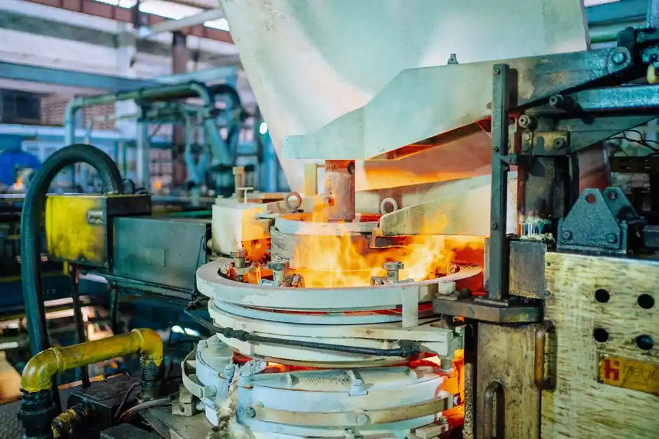
A heat pump assembly line in 2026 is sized around four bottlenecks: cabinet fabrication, refrigeration-circuit brazing and evacuation, inverter-board population, and a final performance test that verifies COP, sound, and refrigerant leak rate before pack-out.
Lines targeting residential mono-block and commercial air-source units sit on takt times of 90 to 240 seconds per station, with refrigeration-loop workstations normally the gating step because of vacuum, nitrogen leak test, and refrigerant charging dwell [S1][S2].
Four-cell architecture for a 2026 air-source heat pump line
A practical line splits into a sheet-metal subassembly cell (casing, chassis, fan shroud), a refrigeration-loop cell (compressor mount, evaporator/condenser brazing, filter-drier, EEV, four-way valve), an electrical cell (inverter board, capacitor bank, contactor, control board, terminal block), and an end-of-line test cell (helium or nitrogen leak, vacuum hold, refrigerant charge, run test, COP verification, sound check) [S1][S3].
Texas Instruments publishes a residential heat pump inverter reference design that anchors the electrical cell: a high-efficiency, low-EMI PFC front end, motor control with enhanced protection, and accurate temperature/current sensing all sit on a single PCB and gate the inverter station cycle time [S1]. The white paper "TI Solutions to Increase Efficiency of Air Conditioner", dated 15 July 2024, is the deepest public reference for component selection on that board [S1].
Refrigeration-loop workstation: the takt bottleneck
The refrigeration loop is where most 2026 lines lose throughput, because the station must torch-braze or induction-braze copper-to-copper joints, pull a vacuum to 50-100 Pa absolute, hold that vacuum for a leak-decay test, and then charge refrigerant by mass to within ±2 g on R290 or ±5 g on R410A systems [S2][S3].
Chinese OEM Jingbo Environmental Equipment Technology publishes fixed-frequency and inverter heat pump platforms including the JBKH-30ZSN1 ultra-low temperature inverter and the JBKH-50ZSN1 fixed-frequency unit, both marketed for commercial sites with multi-module paralleling, which is the typical downstream configuration a line architect must accommodate in the run-test cell [S2]. The same vendor documents a -35 °C low-enthalpy operating envelope on its floor-heating series, which sets the low-end rating point the end-of-line test cell must be able to simulate [S2].
Selection criteria: air-source vs water-source vs geothermal

Architects pick a heat pump family before they pick a line layout. The three main types are air-source, water-source, and ground-source (geothermal), and the choice locks the test cell, the cabinet tooling, and the inverter sizing [S3].
Viessmann's Vitocal 200-A air-source unit ships at 4 to 12 kW heat output, 4.5 to 9.5 kW cooling, and 35 dB(A) noise, which is the residential reference for cabinet sound pass criteria at the end-of-line station [S3]. Carrier's commercial Aquazone 50HQP water-source unit spans 53,800 to 435,000 BTU/h heating and 72,900 to 472,000 BTU/h cooling in 22 to 70 inch cabinet heights, the kind of footprint a heavy-commercial line must plan around [S3]. Mitsubishi Electric's City Multi WY water-cooled series at 25 to 63 kW heat output with 46 to 54 dB(A) noise tiers shows how the test cell is graded for the same platform at different sound ratings [S3]. Architect-engineers comparing platforms should score them on COP at A7/W35, maximum leaving-water temperature, sound power at rated load, and refrigerant charge tolerance, which are the four numbers the test cell must measure anyway.
Inverter-board and motor-control cell
The inverter board drives the line cycle on variable-speed platforms and is the second-most labour-dense station after the brazing cell. A 2026 residential inverter BOM typically includes a PFC stage, an IPM or discrete IGBT inverter, a DSP or MCU motor controller, current shunts, and NTC temperature sensing for the refrigerant and ambient paths [S1].
TI's reference architecture lists four non-negotiable design requirements for that board: high-efficiency, low-EMI power supply with PFC; accurate CO sensing and leakage monitoring; high-efficiency motor control with enhanced protection; and secure, low-power wireless connectivity for service and grid response [S1]. A plant that ignores the CO-sensing and leak-monitoring block ends up retrofitting it on the end-of-line test cell instead, which raises fixture cost and cycle time.
End-of-line test cell: COP, sound, leak rate
The end-of-line cell is the only place a manufacturer certifies the unit, so fixture design drives the test-cell footprint. A residential line typically runs three calibrated test loops: an air-side calorimeter for heating capacity, a water-side calorimeter for heating COP, and an acoustic booth for sound power at A7/W35 and A-7/W35 rating points [S2][S3].
Refrigerant leak rate is gated by a helium mass-spectrometer sniff test or a pressure-decay test on the charged loop, with pass criteria on the order of 0.5 g/yr for R290 and 1.0 g/yr for R410A on residential platforms. Chinese OEM literature for agricultural and aquaculture heat pump platforms claims a COP of 3.5 on standard conditions, which is the lower-bound pass threshold a new line should program into its PLC [S2]. For heavy-commercial units, the test loop must rate at 53,800 to 435,000 BTU/h to match commercial product envelopes, otherwise the test cell becomes a scrap-and-rework hazard [S3].
Line layout, takt balance, and upstream supply
Once the four cells are scoped, line architects run a takt-balance pass. Sheet-metal cells normally run 60 to 120 s, the refrigeration loop station 180 to 300 s, the inverter line 90 to 150 s, and the end-of-line test 240 to 600 s, so buffering between the refrigeration loop and the test cell is standard practice on residential lines [S1][S2].
Upstream, the cabinet and copper-fabrication suppliers feed the line on a JIT call, while the inverter-board subassembly is normally built on a separate SMT line and delivered as a kit; for a working engineer's reference on matching pump and compressor duty to the refrigerant loop, the pump and valve die-casting selection brief lays out the upstream material trade-offs. Where the line also packages a hydronic module, hydraulic pump sizing rules gate the circulating-pump station cycle time. Compressed-air consumption for leak test and pneumatic fixtures is non-trivial, and 2026 compressed-air supply chain tiering is the right read for sizing the air-side redundancy.
Limits, failure modes, and what to track next
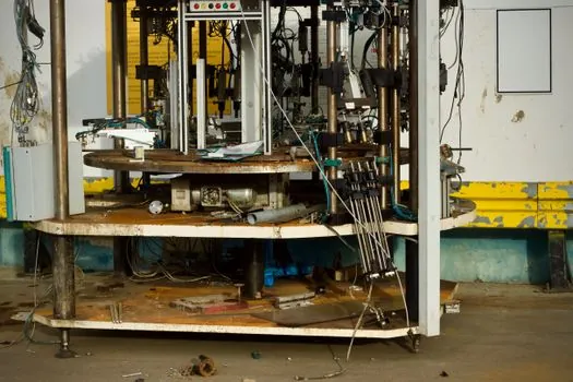
Three failure modes dominate new heat-pump line ramps. First, refrigerant charging drift: a worn mass-flow controller will undercharge R290 units, which then fails the COP pass band on cold-day rating points. Second, vacuum-pump decay: a contaminated pump will not pull below 100 Pa, which inflates leak-test dwell and breaks takt. Third, inverter-board rework: missing the CO-sensing or leak-monitoring block at design time forces a manual retrofit station that adds 30 to 45 s per unit and caps line throughput. [S3]
Trackable signals to watch on 2026 builds: (a) whether new EU F-gas quotas accelerate R290 line conversions and force a charging-fixture refresh; (b) whether inverter reference designs push more motor-control and sensing into the same MCU to shrink the BOM; (c) whether end-of-line acoustic booths scale from 35 dB(A) residential to 54 dB(A) commercial in a single shared cell, which would cut factory footprint [S1][S2][S3].
For component-level specifications, see heat detector, heat treatment furnace, and molding line.