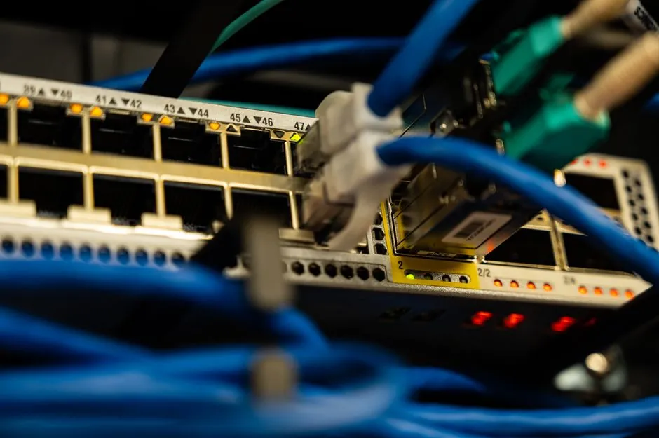
A switch-disconnector is a mechanical switching device that performs both a switching function and an isolating function within its published rating, and the published standard that defines the low-voltage product family is BS EN IEC 60947-3 [S3]. Picking the wrong device is one of the leading causes of photovoltaic-related fires in the UK, which is why the IET published a dedicated selection guide in April 2026 [S3].
The selection problem splits into four buckets: identify the electrical duty, confirm the correct product standard, size voltage and current with explicit safety margins, then check the mechanical, environmental, and safety features for the cabinet or box the device will sit in. The rest of this article walks each bucket with the numbers and standards a spec engineer can defend.
Disconnector vs Isolator vs Switch-Disconnector vs Load-Break Switch
Engineers often treat the four terms as synonyms, but their published duties differ. A disconnector (also called an isolator) is a mechanical device that creates a visible open gap to prove isolation, and is treated as off-load unless its rating says otherwise. A switch-disconnector is assigned both switching and isolating duties inside its published rating, and may make or break specified currents but only within those ratings [S2]. A load-break switch is specifically designed to interrupt normal load current. The practical rule from substation practice: a circuit breaker interrupts current, a disconnector proves isolation, and confusing those two roles is the single most expensive one-line-diagram mistake [S2].
The family tree also includes the switch-disconnector at the centre, surrounded by purpose-built cousins such as the isolating switch for off-load isolation, the load-switch for on-load switching, and the industrial-switch for motor and feeder circuits. Choosing between them is a function of whether the application needs to break load, only isolate, or both, and whether a fuse is integrated for overcurrent protection.
Standards You Must Match Before Looking at Models
The product standard for a low-voltage switch-disconnector is BS EN IEC 60947-3, which covers ratings, making/breaking capacity, and the minimum contact gap needed to prevent restrike across a wide DC voltage range [S3][S5]. For North American industrial machinery, the reference is NFPA 79, which sets the rules for selecting main disconnect switches and the difference between feeder and branch circuits when UL 489 listed devices, molded-case switches, or non-fused disconnects are used [S4].
For DC solar, the IET specifies the designer's first job is to confirm conformity to BS EN IEC 60947-3; AC-rated devices and DC-rated devices are not interchangeable even on the same physical switch body, because the device usually carries two completely different ratings for AC versus DC [S3]. Other relevant rules appear in the national wiring code (BS 7671 in the UK) for installation method and the NEC in the US for the 1.25 continuous-current factor and overcurrent protection sizing [S5].
Voltage Sizing: Voc, Cold-Weather Correction, and 10% Margin
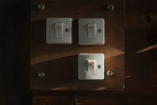
The DC voltage rating of a switch-disconnector must exceed the maximum open-circuit voltage of the array. The standard installer rule is to take the per-panel Voc, multiply by the number of modules in series, correct for the coldest expected local temperature (cold raises Voc on crystalline modules), then add a 10% safety margin to ride through transient overvoltages [S5]. A 1000 V DC switch-disconnector is therefore the typical ceiling for residential and small-commercial strings; anything beyond it usually steps up to 1500 V equipment.
AC side sizing is more forgiving. A typical domestic consumer-unit switch-disconnector is rated 230 V and 100 A, and the AC voltage does not stack with series count, so most designers size only on current and number of phases [S3]. The trap to avoid is reusing an AC-rated device on a DC string: DC switching is far harder to interrupt because there is no current zero crossing, so the device's published DC voltage and current must both be checked independently, not derived from its AC rating [S3][S5].
Current Sizing: Isc, Parallel Strings, and the 1.25 Continuous Factor
For DC arrays, the maximum short-circuit current (Isc) per string multiplied by the number of parallel strings gives the short-circuit current the disconnect must handle. Apply the 1.25 safety factor recommended by the NEC for continuous operation, and you land on a target amp rating. Common sizing bands: residential 10-30 A (select 40 A or higher), commercial 30-100 A (select 125 A or higher) [S5].
For motor and feeder duty on the AC side, the same logic applies but with different multipliers. NFPA 79 uses the feeder/branch distinction to set whether a UL 489 listed molded-case switch, a non-fused disconnect, or a cam switch is the correct device, and the upstream overcurrent device must coordinate with the disconnect's listed ratings [S4]. Oversizing the current rating beyond the calculated value is generally cheap insurance: it extends service life and reduces nuisance tripping, as long as the device's published short-circuit withstand (Icw or Icc) still coordinates with the upstream protective device [S5].
Duty Class: AC-21, AC-22, AC-23, DC-PV, and Why the Code Matters
BS EN IEC 60947-3 defines utilization categories that tell you exactly what the device has been type-tested to make and break. AC-21 covers resistive loads, AC-22 covers mixed resistive and inductive loads with mild overload, and AC-23 covers squirrel-cage motor switching with the heavy inrush expected at start. DC-PV (and the related DC-21/DC-22 categories) covers DC switching with explicit limits on inductive load and on the L/R time constant the contacts must clear [S3].
For comparison, a limit switch and a level-switch are signal-level devices with entirely different utilization categories and belong in control circuits, not in the power path a switch-disconnector is sized for. Confusing them is a common procurement error. The duty code must be visible on the device nameplate or datasheet, and the spec must call it out by code, not by a generic phrase like "disconnect switch".
Safety Features: Arc Suppression, Lockout/Tagout, and Contact Gap
DC switching generates sustained arcs because the current has no zero crossing, so the switch must have an explicit arc-suppression construction (typically magnetic blow-out, contact geometry, or both). BS EN IEC 60947-3 also specifies the minimum contact gap required to prevent restrike and to provide the isolation distance the standard promises [S3][S5]. Lockout/tagout provisions are required by the national electrical code on both sides of the Atlantic and are non-negotiable for any maintenance isolation point.
Environmental suitability is the next gate. Indoor enclosed cabinets usually accept IP2x or IP3x, but outdoor PV combiner boxes need at least IP65, often IP66, plus UV-stable enclosure materials because the device sits next to the array it switches. For utility-scale battery energy storage, the same arc-suppression logic applies but with DC voltages up to 1500 V, and the fuse-switch-disconnector variant (fuse + switch + disconnector in one body) is increasingly specified because it cuts cabinet footprint and removes wiring between separate components [S1].
Fused vs Non-Fused vs Fuse-Switch-Disconnector
A plain switch-disconnector provides isolation and on-load switching but no overcurrent protection, so the protection function has to be supplied upstream by a fuse or circuit breaker. A fuse-switch-disconnector integrates the fuse carrier into the switch body: the fuse element clears the fault in milliseconds, and the integrated switch gives operators a single manual isolation action. The integration matters in high-risk environments such as energy storage and PV because it removes wiring between separate components, which are potential failure points [S1].
The trade-off: fuses are faster and current-limiting, but they are one-shot and must be replaced after a fault. Circuit breakers are reusable and better where the duty is frequent tripping and resetting, such as machine-builder control panels. For PV combiner boxes and battery strings, fuse-based protection is usually preferred for its speed and let-through energy; for general-purpose feeder protection, a UL 489 molded-case switch plus a thermal-magnetic breaker upstream is the NFPA 79 default [S1][S4].
Who Should Not Use a Switch-Disconnector
Do not use a switch-disconnector where the device has to clear a confirmed short-circuit current. That is the circuit breaker's job, and the disconnector's published short-circuit withstand is the fault it can carry without damage, not the fault it can interrupt [S2]. Likewise, do not use a DC-rated switch-disconnector on an AC circuit at its DC nameplate voltage: the two ratings on the same body are independent, and the AC rating is usually lower than the DC rating on the same physical device [S3].
A second group of misapplications is the use of an AC-21 resistive-load switch-disconnector on a motor feeder. AC-23 is the correct utilization category for squirrel-cage motors because it covers the locked-rotor inrush. An AC-21 device on a motor may pass the contactor duty but fail the maintenance switching duty within a few operations. For more on motor-side selection logic that complements this topic, see marine gearbox selection: ratios, types, and power class matched to vessel size.
Selection Checklist and Shortlist Logic
Run this in order: (1) define the duty: off-load isolation only, on-load switching, or fused protection + isolation. (2) Identify the standard: BS EN IEC 60947-3 for low-voltage worldwide, NFPA 79 plus UL 489 for North American industrial machinery, with NEC sizing rules for DC PV. (3) Size voltage: AC side per the system line-to-line, DC side per Voc × series count × cold-correction × 1.10. (4) Size current: AC side per the feeder or branch load with the NEC 1.25 continuous factor, DC side per Isc × parallel strings × 1.25. (5) Match the utilization category (AC-21/22/23 or DC-PV/DC-21/DC-22) to the load type. (6) Confirm safety features: arc suppression, contact gap per IEC 60947-3, lockout/tagout, IP rating for the enclosure. [S5]
If two devices pass all six gates, pick the one with the higher published Icw (short-time withstand) and the better coordination data with the upstream protective device, because coordination is what actually clears a fault safely. For pump and valve cabinets that sit next to a switch-disconnector, the related spec logic in shell molding machine selection for pump and valve production shows how adjacent process equipment follows the same explicit-numbers discipline. Trackable signals to watch over the next quarter: revisions to NFPA 79 in the 2026 amendment cycle, and the IET's next Wiring Matters issue on DC isolation for battery storage, which is expected to extend the IEC 60947-3 selection logic into higher DC voltages and bi-directional string architectures.