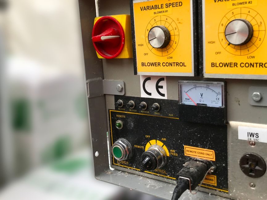
A variable speed drive takes a fixed-frequency AC supply and delivers a variable-voltage, variable-frequency output to the motor — typically 380 V three-phase at 50 Hz on the input side, with output fundamentals from 0 to 599 Hz and, on some architectures, up to 2000 Hz [S2][S3].
The energy case is the headline number: a VSD paired with a NEMA premium or synchronous motor on a variable-torque fan or pump load lets the operator open the damper or throttling valve fully and move flow control to the drive itself, so the motor only draws the power the process actually needs [S1]. For constant-flow systems the VFD is simply clamped to its best-efficiency point, but the cabling distance, grounding, and common-mode voltage handling still have to be engineered, not assumed [S1].
Where a VSD Wins: Variable-Torque Loads and Process Control
Variable speed drives reduce power consumption compared with running a motor at full speed combined with a control valve [S3], and are noted as more energy efficient than inlet vanes and discharge dampers when controlling fans in variable air volume HVAC systems [S4]. On those loads the recommended retrofit pattern is to start with a NEMA premium (or better, synchronous) motor, place the drive upstream of the motor, fully open the existing damper or control valve, and re-route the flow/pressure/temperature/level feedback signal to the drive instead [S1]. That handover also turns the drive into the final control element in the loop, replacing a control valve that would otherwise drop pressure across itself and waste energy [S3].
Beyond energy, a modern drive is a power-conversion brick, a low-level controller, an HMI, and a motor-control solution in one box: rectifier (AC/DC) with optional regenerative front-end and active low-harmonics stage, DC-link, and a 2-level (or multilevel) inverter bridge, with dv/dt, EMC, and sinus filters available as options [S2]. Fieldbus and wired connectivity let it sit inside an automation or safety architecture rather than as a standalone starter [S2].
Where a VSD Loses: Harmonics, Cabling, and Cost
The downsides are electrical, mechanical, and financial. Electrically, the rectifier stage draws non-sinusoidal current and the fast switching edges of the inverter create common-mode voltage on the motor shaft and in the cabling; the cure is active harmonic filters, properly specified drive-to-motor cable (often symmetrical VFD cable with a continuous shield), and a deliberate grounding path from motor back to drive and to earth [S1][S3]. Without that, bearing currents and EMC failures show up within months, not years [S1].
Cost-wise, an AC drive carries roughly twice the power-component count of an equivalent DC drive, and although digital control has closed the control-complexity gap toward 1:1, DC-to-AC conversion of an existing process is still expensive and should only be pursued when a similar reference application from the manufacturer already exists [S3]. For starting-only duties on multiple motors, a simplified VFD with an integrated bypass switch is usually the right pick over a full flux-vector drive [S3]. Soft starters, by contrast, only vary voltage and never frequency, so they belong in a different cost tier altogether [S3].
Selection Criteria: Motor Type, Load Curve, and Feedback

The first gate is motor type. Induction, surface-mounted permanent-magnet, interior permanent-magnet, and synchronous-reluctant machines can all be controlled from a modern drive via a physical-model flux-vector approach, with or without a speed/position sensor, and the drive can auto-tune from the motor nameplate [S2]. That flexibility only matters if the load is genuinely variable; constant-flow and constant-torque profiles waste the drive's capability and erode the payback math.
The second gate is feedback. If the process is variable flow, pressure, temperature, or tank level, the drive needs that transducer wired into it so it can close the loop; a constant-load system can simply run open-loop at best efficiency [S1]. On servo-drive class machinery, the same drive platform also has to manage position, speed, torque, and jerk through dynamic equations rather than just steady-state speed [S2].
Third is electrical environment. Multiple VFDs on one bus need a harmonics plan — either active filters, which analyze the harmonic current drawn by the load and inject a cancelling 180°-out-of-phase component at the point of common coupling, or per-drive passive filtering where the count is low [S3]. Skipping this study up front is the most common cause of unexplained breaker trips and PF-c capacitor damage on retrofit jobs.
VSD vs Soft Starter vs Servo: A Decision Comparison
Three options cover most AC motor speed-control decisions, and the choice hinges on four criteria: speed range, torque quality at low speed, energy savings potential, and installed cost. A soft starter only varies voltage, holds frequency at line, and is the cheapest path when the goal is limited to reduced starting current on a load that will run at full speed once accelerated [S3]. A standard VFD varies both voltage and frequency, delivers its full energy-saving benefit on variable-torque loads, and handles modest low-speed torque via V/Hz or sensorless vector control [S2][S3]. A servo-drive layers closed-loop position and velocity on top of the same power topology, justified only when the application demands precise dynamic motion rather than steady-state flow or pressure control [S2].
For a fan or pump retrofit where the existing throttling valve is the main loss, the VSD wins on every criterion except first cost. For a conveyor that needs soft starts and stops but otherwise runs at one set speed, a soft starter is the rational buy. For a CNC axis or a packaging machine, only the servo class delivers the required position-loop bandwidth, and the VSD's energy story is a side benefit rather than the main reason to specify it.
Installation Rules That Decide Whether the Drive Actually Works
Three installation rules decide whether a VSD retrofit pays back or becomes a maintenance problem. First, keep the drive-to-motor cable as short as the layout allows and use cable specifically designed for VFD service, with the shield grounded at both ends via a low-impedance path back to the drive and to earth [S1]. Second, plan for common-mode voltage from day one — the drive will produce it, and the cure is symmetric cabling, proper grounding, and in severe cases a shaft-grounding ring or insulated bearing on the motor [S1]. Third, decide early whether the drive will receive a 4-20 mA, HART, or fieldbus feedback signal from the existing flow/pressure/temperature transmitter, and confirm that the drive's analog or communication inputs match that signal type before purchase; mismatches here are the single most common commissioning delay [S1][S2].
For multi-motor panels, the related question is how many motors the drive can start in succession and whether the manufacturer offers a simplified starting-only variant with an integrated bypass — both are spec-line items worth confirming in writing rather than assuming [S3]. And for sites with large installed bases, comparing drive efficiency at the actual operating point (not the nameplate) against the stepper-drive or geared alternatives on the bill of materials is the only way to keep the project's payback claim defensible to procurement.
The next signal to watch is the rollout of regenerative and low-harmonics front ends on smaller frame sizes, which removes the need for separate active filters on light-commercial HVAC retrofits. Engineers specifying drives for European chemical-plant builds in 2026 should also confirm ATEX/IECEx certification status for the exact frame and option combination before placing the order, since option codes can change the hazardous-area classification of the assembled unit.
Related analysis: Sand Blasting Machine: Spec-Driven Pros, Cons, and Selection Gates.