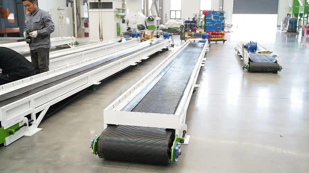
An apron feeder is a heavy-duty mechanical feeder in which overlapping steel pans, carried on two strands of crawler chain running on rollers or tracks, drag bulk material from the outlet of a hopper, dump pocket, or stockpile and meter it onto a crusher, conveyor, or process point at a controlled rate. Where a belt conveyor feeds with a rubber loop that sharp rock and hot clinker destroy, the apron feeder feeds with steel, absorbing the direct impact of rocks falling several meters from trucks or drawdown points and shrugging off abrasive, heavy, sharp material that would shred lighter machines. Metso apron feeder catalogs are representative of the industrial class, and this page treats the complete machine, pans, chains, frame, drive, and skirts, as the purchasing object.
This page is written for the engineer specifying an apron feeder under a primary crusher, a rail or truck dump pocket, a stockpile reclaim tunnel, or a clinker cooler discharge. It works through what the machine does and what is actually being bought, how the pans and chains survive impact duty, which design choices such as pan profile, chain type, and drive placement separate one offering from another, the parameters that recur on vendor data sheets, and the selection factors and RFQ language that decide whether the feeder holds its rate for a wear and maintenance budget that stays predictable.
The decision concentrates in five places: the material and its lump size, because everything downstream follows the worst rock the feeder must swallow; the duty it feeds, gyratory crusher, jaw crusher, conveyor, or process, which sets the interface and rate; the pan and chain design that survives the impact and abrasion; the drive and speed range that gives control authority at the design rate; and the hopper and skirt interface that keeps the material on the pans and the spillage under them. Get those right and the rest of the machine follows with little freedom.
Chapter 1 / 06
What an Apron Feeder Is and What Is Being Decided
The machine this page describes is a steel frame carrying two endless strands of heavy crawler chain, spaced a meter or more apart, on which overlapping pans are bolted so material rides on a continuous moving steel deck. The head shaft, driven through a gearbox by an electric motor, usually with a variable frequency drive, sprockets the chain; the tail shaft takes up slack; and the return strand runs on rollers or slides on guides under the carrying strand. Material loads onto the pans under a hopper opening or at the base of a dump pocket, travels the feeder length, and drops off the head end into the crusher, sizer, or conveyor it serves. Lengths run from a few meters under small hoppers to more than thirty meters in reclaim tunnels, and widths from under a meter to three meters or more in large mining duty.
What is being decided when an apron feeder is purchased is a rate-keeping and survival statement under the worst material the plant produces. The buyer is purchasing the ability to meter a stated tonnes per hour of a stated material, with a stated maximum lump size dropped from a stated height, continuously, with pan and chain wear rates that hold the maintenance budget and with enough control authority at the low end to creep the crusher feed precisely. Everything on the vendor data sheet, width, chain pitch, pan thickness, drive power, speed range, exists to support that statement, and honest vendors size from the material's density, lumpiness, and abrasiveness rather than by copying the last project.
The apron feeder sits in the bulk-handling family with well-defined neighbors that this encyclopedia treats separately. It is not a belt conveyor, which carries finer, gentler material faster and cheaper but dies under direct impact and hot clinker, though the two often work in series, feeder under the pocket and conveyor taking the feeder's discharge. It is not a weigh feeder or a belt scale, which measure mass flow gravimetrically; an apron feeder meters volumetrically by speed and bed depth, and plants that need mass data add weighing elsewhere. In a crushing station it works beside the gyratory crusher or jaw crusher it feeds, often under a grizzly or bar section that scalps fines, and downstream the conveyor train moves product to stockpiles with a belt scale for tonnage and screens and crushers doing the process work.
Different buyers buy the same machine for different materials. A primary mining station buys an apron feeder to sit under a truck dump pocket and feed a gyratory crusher run-of-mine ore that can arrive at more than a meter lump with meters of fall. A cement plant buys one under a clinker cooler or silo to drag hot, abrasive clinker onto conveyors. An aggregate operation buys a smaller feeder under a jaw crusher hopper. A reclaim tunnel buys long, narrow feeders drawing crushed ore from stockpile drawpoints onto the tunnel conveyor. A minerals plant feeds a SAG mill feed bin through one. The material changes every material choice; the machine concept does not.
The economics deserve their own paragraph because the feeder is cheap to ignore and expensive to underbuy. An undersized or under-built feeder becomes the plant's availability ceiling: pans crack under impacts they were not built for, chains stretch, and every failure stops the primary station and everything behind it. Overbuilding has a price too, in steel and power, but the asymmetry is strong, because the feeder's cost is a rounding error against the station it feeds, and the honest sizing posture is to buy for the worst material the mine will send, not the average. Wear parts, pans, chains, rollers, sprockets, are the operating budget, and their life is set by the material and the design at selection; at remote stations the feeder and its pocket run from a diesel generator or gas engine power plant, which makes drive efficiency and restart behavior part of the station's energy budget as well.
A short tour of named duties makes the machine concrete. At a primary crushing station, haul trucks tip run-of-mine ore into a dump pocket lined with rock boxes, an apron feeder draws it at controlled speed under a grizzly section, and the coarse fraction feeds a gyratory crusher with fines bypassing to a conveyor below. In a reclaim tunnel, several feeders draw from stockpile drawpoints onto a tunnel belt conveyor whose tonnage the plant tracks with a belt scale. Under a clinker silo, a slow feeder drags hot clinker onto a deep-pan conveyor or bucket elevator. In each duty the knobs are the same, width, speed, bed depth, and pan class, with numbers that scale while the dragging physics barely changes.
Chapter 2 / 06
How Pans, Chains, and Drives Do the Work
The mechanism is drag conveying on a steel deck. The pans form a substantially continuous surface, overlapping or interlocking so fines do not sift through and lumps do not wedge between them, and the chain strands pull that deck along the carrying run. Material sits on the deck as a bed whose cross-section is set by the hopper opening width and the skirt height at the load zone, and the feeder meters volumetric flow as bed cross-section times speed, which is why speed control on a variable frequency drive is the operator's rate handle and why the hopper interface, not the machine frame, often sets the true maximum rate.
Impact absorption is what the pans are really for. Rock falling meters from a truck dump lands on the pan deck, and the design spreads the blow through pan thickness and profile, flight bars or stiffeners, and the roller or track support under the carrying strand, into the frame and foundations. Pans are thick mild or wear-resistant steel, plain flat in lighter duty, contoured with flights in steeper or wetter service, and supplemented at the load zone by rock boxes, grizzly bars, or dead beds of material that let ore land on ore. A feeder bought without the load-zone design matched to the drop is a machine whose pans are consumables rather than wear parts.
Chains are the machine's structural heart. Heavy crawler chains, engineered chain or specialized track chain depending on the builder, run on flanged rollers along rails or tracks, and their pitch, breaking load, and hardness set what the feeder can drag and for how long. Chain stretch is the consumption symptom: as pins and bushings wear, pitch lengthens, the chain rides out of sprocket engagement, and take-up adjustment reaches its limit, at which point chain replacement is a planned shutdown project. Lubrication philosophy varies by builder, sealed-for-life rollers on many modern machines, automated grease or oil systems on others, and the choice shows directly in the maintenance labor plan.
The drive and speed range set control authority. Most feeders run a single head-drive motor through a helical or bevel-helical gearbox onto the head shaft, with a variable frequency drive giving the speed range, and the sizing question is not the top speed but the turndown: primary stations need to creep at a fraction of design rate during crusher stalls and starts, and a feeder that cannot run slow and smooth cannot protect its crusher. High-torque demands at start under full load, the worst case is starting with material on board after a trip, size the drive more than running power, and backstops or holdbacks keep the loaded deck from running backward when power is lost.
The hopper and skirt interface is where feeders succeed or fail in operation. The hopper opening must be wide enough that the material's worst lump bridges nothing, the skirts that contain the bed on the pans must be tall and hard-faced against the same lumps, and the gap between skirt and pan line is managed with seals or rubbing strips to keep fines from flushing out. Under the feeder, spillage from chain-carryback and sifting is collected on dribble chutes or a small screw conveyor, because a primary station that lets spillage build under the feeder is buying fires and structural damage. None of this is optional interface steel; it is part of the machine's duty and belongs in the RFQ scope.
Wear runs underneath everything. Pan tops gouge and thin under abrasive ore, skirt faces erode, rollers and tracks wear to steps, sprockets hook, and chains stretch, and each interface has an inspectable symptom, spillage, noise, pitch growth, that a trained crew reads at shutdown. The vendor's wear expectation in operating hours or tonnes for the named material, and the exchange philosophy, pans in segments in place, chains in strands, rollers from outside, set the maintenance calendar the buyer actually buys. A feeder whose wear parts need the pocket emptied to service was specified for the wrong station.
Chapter 3 / 06
Feeder Types, Duty Positions, and Machine Boundaries
Pan classes separate light, medium, and heavy machines. Light-duty feeders, thinner pans on smaller chain, serve crushed material and moderate impact, cement raw meal, aggregate, finished minerals. Medium-duty takes run-of-quarry lumps and moderate drops; heavy-duty, thick cast or fabricated pans on large crawler chain with impact-rated carrying runs, takes direct truck or shovel dumps and meters crusher feed in primary stations. Within a class, pan profile differs by duty: flat pans for free-draining dry material, flanged or contoured pans for steep inclines and wet sticky feeds, and stationary-grizzly or vibrating-grizzly sections ahead of the feeder scalp fines so only coarse lumps ride the deck to the crusher.
Duty positions name the feeder's job. Under a primary gyratory crusher or jaw crusher station, the feeder draws from a dump pocket and meters crusher feed, with a grizzly or vibrating screen section scalping fines past the crusher. In reclaim tunnels, feeders draw from drawpoints under stockpiles onto the tunnel conveyor. Under bins and silos, including clinker silos and SAG mill feed bins, feeders control discharge onto conveyors or directly into the mill feed chute. On shiploaders and rail dumps, feeders meter from holding pockets to the conveying train. The same machine class appears at each position with different width, speed, and wear settings, and the RFQ must name the position because it changes the impact, interface, and control requirements.
Adjacent machines mark the boundary. The apron feeder is not the belt conveyor it feeds, whose rubber loop carries the fine, fast, long-haul duty this page's steel deck is wrong for; the two work in series at most stations. It is not the weigh feeder, whose gravimetric belt measures mass flow while metering, nor the belt scale that instruments a conveyor after the fact; an apron feeder meters volumetrically and plants add the weighing where the process needs mass. It is not a vibrating screen or grizzly, though grizzly sections bolt ahead of it and a vibrating screen often receives its product. Upstream it interfaces with hoppers, pockets, and stockpile drawdowns; downstream with crushers, sizers, and conveyors, and stations that add tertiary reduction may feed a high pressure grinding roll from the same conveyor train. In concentrator service the product ends in the grinding train, SAG mill or ball mill, whose trommel screen discharge closes the circuit, with the whole plant's tonnage read from the conveyor belt scale.
Competing feeder architectures frame the choice inside the same duty. Vibrating pan feeders shake material along a trough and suit lighter, finer duty with less impact. Belt feeders, a short heavy belt in a chute, suit finer materials and blend bins where gentle handling matters. Push-pull reciprocating plate feeders serve small hoppers. The apron feeder wins where impact, lump size, abrasion, or heat rule those lighter machines out, which is why primary mining stations, clinker handling, and heavy reclaim are its home ground, and a selection that does not state the worst-case lump and drop is choosing between feeder classes blind.
Support and take-up arrangements differ by builder but share the family logic. Carrying runs ride on flanged rollers bolted to the frame at close pitch in impact zones, wider elsewhere; return runs run on return rollers or slide strips; the head shaft carries the drive sprockets and the take-up lives at the tail with screw or hydraulic adjustment. Frames are fabricated steel beams designed for the full material load plus impact dynamic factors, and in reclaim tunnels the feeder frames become part of the tunnel structure with gates at drawpoints. Skirt boards, spillage decks, covers, and dust enclosures complete the machine as installed, and their scope must be named in the buy rather than discovered missing at commissioning.
Chapter 4 / 06
Key Specification Parameters
The vendor data sheet for an apron feeder centers on width, chain, speed, and drive, and each number carries a duty consequence. The table below lists the parameters that recur across manufacturers' catalogs from light aggregate machines to heavy primary mining duty, with typical ranges a buyer will see. Values for a specific project come from the material's density, lump distribution, and abrasiveness plus the station's rate and drop geometry, and the ranges here are orientation, not a substitute for that engineering.
Parameter
Typical catalog range
What it decides
Feeder width (pan line)
0.8 to 3.5 m
Maximum lump accepted; volumetric capacity
Feeder length
2 to 35 m
Hopper or tunnel geometry; chain load
Chain pitch, heavy crawler
roughly 150 to 400 mm class
Breaking load; wear life; sprocket design
Speed range
0.01 to 0.4 m/s
Rate control; turndown authority for crusher trips
Capacity
tens to over 6,000 t/h
Bed cross-section times speed at design
Installed power
5 to 200+ kW
Start under load; incline; drive class
Maximum lump size
to 1.5 m+ at primary stations
Pan class; grizzly design; crusher interface
Drop height at load zone
station specific, meters
Impact design; rock boxes; pan thickness
Incline capability
0 to 25 degrees typical, profile dependent
Pan profile; flighted pans for steeper runs
Pan and chain service life
ore specific, in years or Mt
Wear budget; exchange cadence
Three of these numbers deserve the buyer's suspicion when they arrive without a basis. Capacity quoted without the bed cross-section and speed it assumes is a brochure number that the hopper interface will not deliver. Lump size quoted without the drop height hides the impact case that actually sizes the pans. Drive power quoted at running condition without the start-under-load case leaves the worst torque demand, a restart with a full deck after a trip, outside the design. An RFQ that asks for the basis of each figure, material data, station geometry, and vendor standard practice on comparable installations, separates engineered offers from assembled ones.
Materials and construction follow the material. Pan bodies are mild or low-alloy steel with weld-overlay or bolted wear surfaces in abrasive duty; chain components are engineered alloy steels with hardened pins, bushings, and rollers; sprockets are fabricated or cast with replaceable tooth segments in heavy duty; and skirts and chutes are wear plate throughout the load zone. Tramp metal handling belongs in the scope, magnets or metal detectors on the downstream conveyor, because crawler chains do not forgive a wrench. Each wear interface has a stated replacement expectation for the named material, and the buyer should hold the offer to that basis rather than to a generic heavy-duty label.
Chapter 5 / 06
Selection Decision Factors and RFQ Language
Selection starts with the material, not the catalog. Density, lump size distribution, abrasiveness, moisture and stickiness, and the drop geometry at the load zone together decide the pan class, the impact design, and the width; the station's design and maximum rate decides speed range and drive; and the interface, what the feeder feeds and what feeds the feeder, decides length, skirts, grizzly, and enclosure. A material test or a reference on the same ore beats any calculation imported from another commodity, and the worst-case lump, not the average, is the sizing lump.
The duty position decides the machine's refinement level. A primary dump-pocket feeder wants the heaviest pan class, full impact zone engineering, grizzly integration, and a drive with deep turndown to nurse its crusher through stalls. A reclaim tunnel feeder wants length, drawpoint gates, and wear surfaces matched to years of buried service with difficult access. A bin or silo feeder wants precise low-speed control and dust-tight enclosure. Buying one class for another duty wastes steel in one direction and availability in the other, and the vendor's first question, correctly, will be the station arrangement drawing.
The table below organizes the decision into the factors that recur across projects, with the questions the buyer should be able to answer before the RFQ goes out. Each row is a place where an incomplete answer becomes an underspecified feeder and an availability argument later.
Decision factor
What the buyer must state
Consequence if left open
Material
Density, lump distribution and max size, abrasion, moisture, temperature
Pan class and impact design guessed; pans become consumables
Duty and interface
What the feeder feeds, gyratory crusher, jaw crusher, conveyor, bin; what feeds it
Interface steel and control mismatched to the station
Rate and control
Design and maximum tonnes per hour, required turndown for trips
Drive undersized for restart; crusher starved or choked
Drop and impact
Drop height at load zone, rock boxes or grizzly intent
Impact case outside design; premature cracking
Layout
Length, incline, reclaim gates, access for maintenance
Exchange space missing; wear service becomes demolition
Wear environment
Expected pan, chain, roller life for the named material
Wear budget and cadence undefined
Enclosure and dust
Covers, skirts, spillage and dust control scope
Spillage and compliance problems land late
RFQ language for an apron feeder should name the material and the station. A workable specification states: material with density, moisture, temperature where relevant, lump size distribution and maximum lump, and abrasiveness basis; design and maximum tonnes per hour with required turndown; station arrangement with hopper or pocket geometry, drop height, and what the feeder discharges to; pan class and profile intent with the impact-zone design basis; chain specification with expected service life for the named material; drive scope, motor, gearbox, variable frequency drive, backstop, and restart-under-load capability; skirt and interface scope with grizzly intent if used; spillage and dust handling; instrumentation, speed sensing, and control interface to the station; and the acceptance basis, rate verification at speed, no-load and loaded run, and noise and vibration limits. Naming the interface equipment, the gyratory crusher or jaw crusher at the head, the belt conveyor and belt scale taking discharge, and any vibrating screen in the station, lets vendors bid the connections correctly.
Chapter 6 / 06
Installation, Standards, Failure Modes, and Maintenance
Installation is a structure-first job. Foundations and pocket steel take the full material load plus dynamic impact factors, so anchor design follows the vendor's load schedule; the frame is set and surveyed, head and tail shafts aligned, chains and pans assembled or the delivered deck spliced, and rollers and tracks adjusted to line. Skirts, grizzly sections, covers, and dribble handling install with the machine because the station cannot run without them. Commissioning runs the drive in both directions on barring first, then at speed empty, then with material in steps, checking chain tracking, sprocket engagement, spillage behavior, and rate against the belt scale on the downstream conveyor.
Standards for apron feeders are machine and station codes rather than a single machine standard. Frames follow structural practice for the jurisdiction; drives, gearboxes, and motors follow rotating machinery and electrical specifications; guarding follows machine-safety practice around chains and sprockets, which are unforgiving entanglement hazards; and conveying practice for bulk handling installations covers enclosures and dust. There is no single international apron feeder standard that governs the machine end to end, so the RFQ must name the applicable structural, mechanical, and electrical codes and the vendor's own manufacturing standards for chain qualification, pan welding, and gearbox rating. Any edition reference should be verified current at purchase rather than copied from an old specification.
The recurring failure modes are wear-and-overload patterns with honest symptoms. Pan cracking at welds under impacts beyond the design case announces itself in spillage and noise and is surveyed at shutdown; chain stretch, measured as pitch growth at the take-up, schedules replacement before sprocket jumping forces it; roller and track wear steps the deck and shows as carryback and tracking drift; sprocket tooth hooking changes engagement noise and wear metal in the oil where monitored. Overload events, tramp steel or a frozen pocket start, load the drive to its backstop and torque limits, which is where undersized drives fail first. Spillage management failures, dribble chutes blocked and piles building under the deck, cause the structural and fire damage that station audits remember.
Maintenance planning is interval driven and access shaped. The table below lists the recurring items with the typical cadence a plant will schedule, assembled from common vendor practice; actual intervals follow the material's abrasion and the station's utilization and should be reset from the first year of survey data.
Item
Typical action
Typical cadence
Pans and wear surfaces
Survey thickness and cracks, renew wear plates or segments
Quarterly checks, renewal per wear
Chains
Measure pitch growth, adjust take-up, plan replacement
Monthly measure
Rollers and tracks
Inspect wear steps, lubricate or replace rollers
Monthly to quarterly
Sprockets and shafts
Tooth wear check, oil or grease service
Quarterly
Drive and backstop
Torque check, vibration survey, gear oil sample
Quarterly
Skirts and seals
Renew hard-facing and rubbing strips
Monthly checks
Spillage and dribble system
Clear dribble conveyors and chutes, inspect under-deck
Weekly
Long-term care keeps the station's availability honest. As the mine or quarry deepens, lump size and abrasiveness drift from what was specified, and the pan class or wear design that was right at commissioning slowly becomes wrong; periodic wear-rate audits against the baseline caught at selection schedule the upgrades before failure does. Chain and roller metallurgy improvements, better seals, and automated lubrication retrofit to existing machines and often pay in labor alone. The plant that treats the feeder as the primary station's gatekeeper, measured every shutdown and adjusted, is the plant whose crusher never starves and whose under-deck stays clean in year fifteen.
FAQ
When should an apron feeder be chosen over a belt feeder?
Choose an apron feeder when the material punishes lighter machines: large lumps dropping directly from trucks or drawpoints, sharp abrasive ore, hot clinker, or deep beds needing strong control at low speed. Choose a belt feeder for finer, gentler materials in blend bins and process hoppers where a rubber belt's gentleness and cleanliness win. The dividing cases are wet sticky fines, which can bind an apron's pans but also seize belt scrapers, so the honest answer runs material tests and a reference check on the same commodity before committing the station.
How is apron feeder capacity determined?
Volumetrically: the bed cross-section the hopper opening and skirts allow, times the pan-line speed. The bed cross-section is set by width and effective skirt height at the load zone, so the hopper interface, not the machine frame, often caps the real rate. Sizing states design and maximum tonnes per hour from material density, checks the speed range that delivers both, and checks turndown for crusher-trip creep. Capacity quoted without the assumed bed depth is a brochure number the station will not reproduce.
What is the difference between light, medium, and heavy duty pans?
Pan class follows impact and load. Light duty serves crushed, finished, or moderate materials with thinner pans on smaller chain; medium duty takes run-of-quarry lumps and moderate drops; heavy duty uses thick cast or fabricated pans on large crawler chain with impact-rated roller support, sized for direct truck dumps and primary crusher stations. The class sets pan thickness, chain pitch and breaking load, and frame design together, and buying one class down from the duty turns pans from wear parts into consumables.
How fast can an apron feeder run and why do they run slowly?
Pan-line speeds are typically a few centimeters per second to about a third of a meter per second. The low speed is the point: chains are high-torque, low-speed machines whose wear life falls sharply with speed, whose sprocket engagement wants slow mesh, and whose duty, metering crushers and drawpoints, needs deep turndown rather than velocity. Stations that need high tonnage widen the feeder rather than speeding it, keeping chain wear and control authority in the designed envelope.
What maintenance does an apron feeder need?
Interval-driven wear care: measure chain pitch growth monthly and plan replacement before sprocket jumping; survey pan thickness and cracks quarterly and renew wear plates; grease or inspect rollers and tracks on schedule; sample gearbox oil and check backstops; renew skirt hard-facing; and keep dribble conveyors and under-deck clear weekly. Access is part of the maintenance design, so the RFQ should require exchange space for chains, pans, and rollers, because wear service that needs the pocket emptied was specified for the wrong station.
How does an apron feeder control crusher feed rate?
By speed on a variable frequency drive, with the bed depth set by the hopper opening and skirts. The drive's turndown range is the control authority: primary stations need to creep at a fraction of design rate during crusher stalls, starts, and belt trips, and the feeder must also restart with a full deck after power loss, which sizes the drive's torque and backstop more than running power. Rate feedback comes from the downstream conveyor belt scale in most stations, closing the loop through the plant control system.
What should an apron feeder RFQ include?
State the material with density, lump distribution and maximum lump, abrasion, moisture, and temperature; design and maximum tonnes per hour with required turndown; the station arrangement, hopper or pocket geometry, drop height, and the crusher or conveyor being fed; pan class and impact-zone design basis with grizzly intent; chain specification with expected service life for the named material; drive scope with restart-under-load capability and backstop; skirt, spillage, and dust scope; instrumentation and control interface; and the acceptance basis, rate at speed verified against the downstream belt scale with loaded run witnessed. Naming interface equipment, gyratory crusher or jaw crusher at the head and the conveyor train below, lets vendors bid the connections correctly.