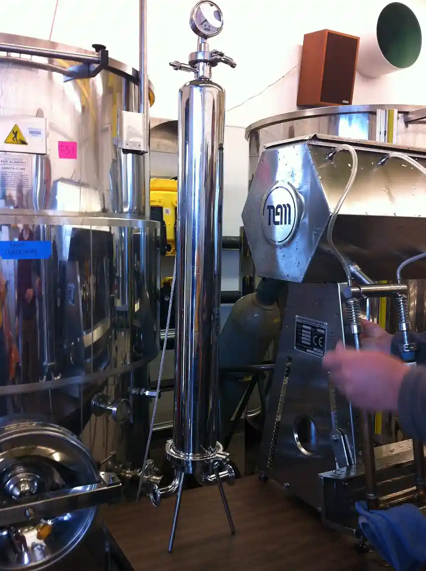
An induced gas flotation, or IGF, unit is the produced-water and oily-water machine that cleans water of dispersed oil by inducing, rather than dissolving, a fine swarm of gas bubbles into it: eductors or a mechanical aerator entrain gas from the vessel's headspace or a supply, the bubbles shear into the water, oil droplets and oil-wet solids attach to them, and the buoyant aggregates rise into a skimmed oil layer that leaves the machine as recovered oil while the cleaned water discharges from the far end. Horizontal multi-cell vessels, four flotation cells in series in the classic offshore design, dominate oilfield duty; vertical compact units serve tight footprints. CETCO CrudeSep and Siemens Hydrocell machines are representative of the industrial class, and this page treats the complete unit, vessel, induction system, skimming, and controls, as the purchasing object.
This page is written for the engineer specifying an IGF unit for offshore or onshore produced water, refinery or terminal oily water, or any dispersed-oil removal duty. It works through what the machine does and what is actually being bought, how the bubbles and the chemistry do the work, which design choices such as induction type and cell count separate one offering from another, the parameters that recur on vendor data sheets, and the selection factors and RFQ language that decide whether the unit holds its outlet oil number on the real water.
The decision concentrates in five places: the water and its oil, dispersed droplet size and stability, total oil and solids load, and the outlet target, because emulsion chemistry writes the whole specification; the machine architecture, horizontal multi-cell or vertical compact, that fits the footprint and the flow; the induction system, hydraulic eductors or mechanical aeration, with its bubble population and energy; the chemical program, demulsifier and coagulant, that makes the oil attachable; and the downstream polishing, the interface this unit leaves to filters or separators. Get those right and the discharge permit sleeps.
Chapter 1 / 06
What an Induced Gas Flotation Unit Is and What Is Being Decided
The machine this page describes is a tank or vessel, steel, atmospheric or lightly pressurized by the duty, divided internally into cells by underflow-and-weir baffles so the water steps through a series of quiet zones. In each cell an induction device, eductor nozzles on a recirculated water stream in the hydraulic design, or a shaft-driven aerator in the mechanical one, entrains gas and shears it into bubbles tens to hundreds of micrometers across; the bubbles mix through the cell, oil droplets and oil-wet solids attach, and the aggregates float to the surface where a skimmer, paddle or weir, sweeps the oil layer to a trough for recovery. Clean water leaves the last cell over a level-controlled weir; float solids and recovered oil go to storage or reprocessing, and the machine runs continuous on a water stream that arrives from upstream separation.
What is being decided when an IGF unit is purchased is an outlet oil statement on a defined water. The buyer is purchasing the ability to take a stated flow of stated water, produced or process, with stated inlet oil and solids and a stated emulsion character, and deliver a stated outlet oil content, commonly from a few hundred parts per million down toward ten or twenty on well-behaved water, continuously, with a chemical consumption and a maintenance load that hold. Everything on the vendor data sheet, cell count, induction energy, retention, recirculation rate, exists to support that statement, and honest vendors size from bottle tests and witness trials on the actual water rather than by copying the last project.
The IGF sits in the oil-water family with well-defined neighbors that this encyclopedia treats separately. It is not the dissolved air flotation, DAF, unit of municipal and industrial water duty, which dissolves air under pressure and releases it as much finer bubbles for flocs rather than oil, a different physics with a different feed, though the two share the flotation word and the skimmed surface; and it is not the mining flotation-cell, whose mineral froth duty, reagents, and machine scale are another world. It is not a gravity separator: the API and CPI designs and the plain oil-water-separator machine remove free oil by rise alone and typically precede it; the three-phase-separator and heater-treater of the production train sit further upstream; and the coalescing-filter or polishing media beds follow it. Its upstream neighbor in a refinery is often the desalter train's wastewater, and its downstream is discharge or reinjection.
Different buyers buy the same machine for different waters. An offshore platform buys a horizontal multi-cell IGF for produced water ahead of overboard discharge, footprint and weight the currencies, fuel gas or produced gas the bubble supply. An onshore oilfield buys the same design for reinjection water, where oil protects the reservoir's injectivity. A refinery buys IGF or its cousins for wastewater ahead of biological treatment, the oil that would poison the bugs removed here. A terminal or ballast-water plant cleans tanker water with the same physics. The water's chemistry, salinity, temperature, and emulsion stability, writes every setting; the machine concept does not change.
The economics deserve their own paragraph because IGF is bought against a permit number. The outlet oil limit, overboard or reinjection, is a regulatory or reservoir line, and the unit's cost is weighed against its chemicals, its power, its footprint offshore where steel and weight price like machinery, and its availability; recovered oil is a small credit, returned to the process. Against downstream polishing, nut-shell media filters or similar, the IGF carries the bulk removal cheaply and the polisher carries the final number, and the split of duty between them is the design's real economics rather than any single machine's price.
A short tour of named duties makes the machine concrete. On a floating platform, produced water from the separation train's free-water knockout flows through a four-cell hydraulic IGF, eductor bubbles on each cell's recirculation, demulsifier dosed upstream, oil skimmed to a recovered-oil header, water overboard at the permit number. At a refinery, desalter drains and process water pass an equalization tank then an IGF ahead of the biological plant. At an onshore waterflood, produced water floats then filters then reinjects. Each duty names the same knobs, induction energy, cell count, chemical, and retention, with numbers that scale while the bubble physics never changes.
Chapter 2 / 06
How Bubbles, Chemistry, and Rise Do the Work
The mechanism is attachment and buoyant rise. A gas bubble and an oil droplet collide in the turbulent induction zone; if the oil's surface state allows, the film between them drains and ruptures, the droplet adheres, and the bubble-droplet aggregate, far lighter than water, rises at a Stokes velocity set by its effective size. Many small bubbles present many collision surfaces, and the swarm's total flux carries the attached oil upward into the skim layer. Everything the machine does, induction energy, cell count, chemical dosing, residence, exists to raise collision probability and rise flux while protecting the skimmed layer from re-entrainment.
Induction is the machine's signature. In hydraulic IGF, a recirculation stream, a fraction of the machine's own water pumped through eductor nozzles in each cell, entrains gas from the headspace by venturi action, no moving parts in the vessel; the recirculation rate and nozzle pressure set the bubble population. In mechanical IGF, a shaft-driven aerator, an impeller-and-stator assembly like a gentle flotation machine, draws and shears gas, with the induction energy directly on the shaft. Hydraulic designs suit offshore's maintenance aversion; mechanical designs give higher induction energy where the water is stubborn, and vendors offer both families on the same vessels.
Chemistry licenses the physics. Free oil attaches readily; dispersed and emulsified oil, stabilized by surfactants, asphaltenes, and fine solids, does not, and a demulsifier or coagulant program, bottle-tested on the actual water, neutralizes the stabilization so droplets and bubbles meet. Dosage points upstream or in the first cell, polymer aids in some services, and pH where the water allows are the program's handles. The chemical program is as much part of the purchased system as the vessel, and a vendor quoting the machine without asking about the water's chemistry is quoting half a job.
Cells in series buy the residence and the quiet. A single mixed tank loses attached oil to re-entrainment in its turbulence; a multi-cell design separates induction zones from quiescent zones, underflow baffles stepping the water forward while floats and skimmers work each surface, so attachment has its violence and rise has its calm. Four cells is the classic count, three to six the practical range, and the trade is footprint against performance; retention, a few minutes per cell, tens overall, sets the machine's volume at the design flow, and rise rate, the surface loading the aggregates can clear, sets its plan area the way any clarifier's does.
Skimming and interface management recover the floated oil. Paddle skimmers sweep the surface layer to a trough; weir designs let the layer build and overflow; both deliver a recovered stream of oil with some water to storage or the process's oil side. The skimmed layer is a working surface, and the operator's adjustment of skimmer speed and weir position, watched against the outlet trend, is part of the machine's daily reality. The oil-water interface and the water level, held by level controls and a control-valve or pump arrangement on the outlets, keep the skimmer at the layer and the discharge at the weir, and the machine's instrumentation, interface level, oil-in-water analyzers on outlet where the permit warrants, closes the loop the operator watches.
Gas supply and safety follow the duty. Offshore, produced or fuel gas is the natural bubble supply, its hydrocarbons vented from the vessel's headspace to a safe location, and the machine's hazardous-area rating follows; nitrogen or air serve where gas is unsuitable, air bringing its own hydrocarbon-in-air discipline offshore. The vessel vents, the skimming's oil handling, and the induction recirculation's pumps, small centrifugal pump lineups with variable frequency drive options in modern packages, complete the machine's utilities, and offshore designs certify the whole assembly for the platform's rules.
Chapter 3 / 06
Machine Types, Duty Positions, and Boundaries
Horizontal multi-cell vessels are the oilfield standard. A rectangular or cylindrical shell, four cells stepped by baffles, eductor induction on each cell's recirculation, paddle skimmers on each surface, and a single machinery seat for pumps and dosing, the design packs proven performance into a footprint offshore tolerates; capacities run from hundreds to tens of thousands of barrels per day of water. Vertical compact units stack the same physics in a cylinder, induction at the center, rising and falling annuli, and a skimmed top, for tight decks and smaller flows, and their packaged skid form ships complete. Both families carry the same guarantee logic, cell by cell or stage by stage.
Duty positions name the machine's contracts. In offshore production, IGF follows the primary separation train, receiving produced water from the free-water knockout or three-phase separator, and precedes overboard discharge or reinjection, with a polisher, nut-shell media or similar, where permits are tight. In onshore waterfloods the same chain serves the injection wells. In refinery wastewater, IGF follows equalization and API separation, removing emulsified oil ahead of biological treatment, with the desalter drains among its feeds. In terminals and industrial plants, oily water from drains and ballast floats ahead of discharge. The position writes the feed's character and the outlet's number; the machine stays the same.
Adjacent machines mark the boundary. Upstream, the free oil and solids have already left in the production train, three-phase-separator, heater-treater, or knockout services, and any plain oil-water-separator or API design has taken the free rise; the IGF takes what is dispersed. Downstream, polishing is the coalescing-filter or media filter's work, and the biological plant or the reinjection wells receive what this unit delivers. On the same produced-water plant, hydrocyclone deoilers, which the live cyclone-separator page treats as a cousin machine, compete for the same duty, and the honest selection runs the water through both machines' bottle tests rather than trusting either's brochure. In municipal duty the dissolved-air-flotation machine takes the name and the clarifier takes the quiet; neither is this machine.
Package and installation classes separate offerings. Offshore units arrive as certified skids, vessel, induction pumps, chemical package, and controls on one frame, built to the platform's code and weight regime; onshore plants install the same equipment on foundations with room to service. Materials follow the water: carbon steel with coatings on produced water, stainless internals where sour or corrosive service writes them, and linings where the water's chemistry demands. Retrofits, adding eduction or cells to existing vessels, are common on brownfield platforms, and vendors quote them against the same outlet guarantees as new steel.
The wider water plant deserves a paragraph because IGF never stands alone. On a produced-water installation, upstream solids have been gutted by the headworks of separation and, in refinery service, by screens and settling; where fine solids load the water, their removal by desanding or settling neighbors protects the IGF's skimming. Downstream, float sludges and recovered oil dewater through a decanter-centrifuge, a screw-press, or a filter-press in some plants, the dried cake leaving by screw conveyor, and the skimmed oil returns to processing; the water's final polish, filters and analyzers, closes the permit. On refinery sites the whole oily-water train sits beside the headworks machinery, bar-screen and grit-classifier equipment among it, that the storm and sewer flows cross, and on offshore platforms the IGF's neighbors include the sea-water and utility systems the living platform shares.
Chapter 4 / 06
Key Specification Parameters
The vendor data sheet for an IGF unit centers on flow, cells, induction, and outlet oil, and each number carries a duty consequence. The table below lists the parameters that recur across manufacturers' catalogs for horizontal and vertical machines, with typical ranges a buyer will see. Values for a specific project come from the water's characterization and bottle tests, and the ranges here are orientation, not a substitute for that work.
Parameter
Typical catalog range
What it decides
Design water flow
hundreds to 100,000+ bbl/d
Vessel size and count; cell sizing
Cell count
3 to 6, 4 classic
Stage separation; residence in quiet zones
Retention time
3 to 5 min per cell class
Rise completion; footprint
Inlet oil content
50 to 1,000+ ppm typical
Loading; chemical program intensity
Outlet oil content
10 to 50 ppm class target
Permit or injection compliance
Removal efficiency
80 to 95+ percent typical
The machine's core performance claim
Induction type
hydraulic eductor or mechanical
Energy; maintenance profile; bubble field
Recirculation rate
fraction of throughput per cell
Bubble population; mixing energy
Chemical dosage
water-specific, tens of ppm
Operating cost; attachment license
Package weight and footprint
offshore-priced dimensions
Deck space; installation cost
Three of these numbers deserve the buyer's suspicion when they arrive without a basis. Outlet oil quoted without the inlet water's characterization and the chemical program behind it is a number from someone else's field. Removal efficiency quoted on free-oil-rich water flatters performance on stable emulsions. Retention quoted as total volume ignores the quiet-zone fraction where the rise actually happens. An RFQ that demands the bottle test and the witness trial basis separates engineered offers from assembled ones.
Materials and construction follow the water and the site. Vessels are coated carbon steel on produced water, stainless or alloy where sour and corrosive service writes them, with internals, baffles, skimmers, eductors, in matched materials; offshore packages carry the platform's certification regime from structural to hazardous-area; and chemical packages, dosing pumps and tanks in materials the chemical tolerates, ride the skid. Instrumentation, interface and level with a pressure transmitter or bubbler where the service uses them, outlet oil analyzers where the permit warrants, completes the machine as an operating unit.
Chapter 5 / 06
Selection Decision Factors and RFQ Language
Selection starts with the water, not the catalog. The oil's droplet size and stability, from a fresh sample, the total oil and solids, the salinity, temperature, and pH, and the outlet target decide whether IGF is even the right class, against hydrocyclones upstream and polishers downstream, and which architecture fits; bottle flotation tests on the actual water, with and without chemical, are the honest basis, and vendors offer witness trials precisely because field water humbles catalog numbers. Feed variability, slugs of oil, chemical upsets, belongs in the duty statement because it writes the design margin.
The architecture and site decision frame the offer. Horizontal multi-cell machines buy proven stage separation for footprint; vertical compact units buy footprint for capacity; hydraulic induction buys maintenance-free vessels where mechanical induction buys induction energy; and offshore adds the certification, weight, and plot regime that prices every kilogram. The chemical program is selected with the machine, demulsifier by bottle test, and its annual cost belongs beside the machine's price in the comparison. Downstream interface, polisher or discharge, and upstream, the separator train's water quality, bound the guarantee both sides.
The table below organizes the decision into the factors that recur across projects, with the questions the buyer should be able to answer before the RFQ goes out. Each row is a place where an incomplete answer becomes an underspecified unit and a permit argument later.
Decision factor
What the buyer must state
Consequence if left open
Water characterization
Oil droplet and stability, solids, salinity, temperature
Machine class guessed; guarantee is void
Target and permit
Outlet oil limit, test basis, slug tolerance
Compliance margin unknown
Architecture
Horizontal or vertical; hydraulic or mechanical
Footprint and maintenance mismatched
Chemical program
Bottle test basis, dosage expectations, supply
Attachment fails; outlet number missed
Site regime
Offshore certification, weight, plot, hazardous areas
Package fails its installation rules
Interfaces
Upstream water quality; downstream polisher or discharge
Guarantee boundaries contested late
Utilities
Gas supply, power, chemical storage space
Skid scope disputes late
RFQ language for an IGF unit should name the water and the number. A workable specification states: the water source and its characterization, design and maximum flow, inlet oil and solids ranges, and emulsion behavior with sample or bottle test data; the outlet oil target with its test basis and the slug and upset tolerance expected; architecture intent with vendor free to propose within it; induction type and per-cell sizing with recirculation rates; chemical dosing scope with the program's supply basis; materials for the water's chemistry and, offshore, the certification regime; instrumentation and outlet monitoring scope; package dimensions and weight limits; and the acceptance basis, a witness trial or performance test on the actual water at flow against the outlet number with chemical consumption logged. Naming the interface equipment, the separator train's free-water knockout drum upstream and the polisher or discharge downstream, lets vendors bid the connections correctly. A sampling and analysis protocol, method, frequency, and reporting, agreed in the RFQ, is what makes the outlet number a contractual reality rather than a dashboard belief, and both parties should initial it before the steel is cut.
Chapter 6 / 06
Installation, Standards, Failure Modes, and Maintenance
Installation is skid or vessel work with services around it. The unit sets on its foundation or deck seat, water, oil, gas, chemical, and vent lines connect, and the level and skimming controls commission with water first, then with the real flow in steps toward the acceptance trial. Offshore packages arrive certified and mostly commissioned shop-side, their site work being setting, tying, and proving. Operator training on the chemical program and the skimming adjustments matters as much as the mechanical completion, because the machine's performance is operated, not just installed.
Standards for IGF units are vessel, offshore, and discharge practice rather than a single machine standard. Pressure-retaining parts, where the design uses them, follow the pressure code of the jurisdiction; offshore packages follow the platform's structural and safety certification regime; and the outlet number follows the discharge permit's test basis, overboard rules offshore, effluent limits onshore. There is no single international IGF standard governing the machine end to end, so the RFQ must name the applicable vessel, offshore, and discharge codes and the vendor's manufacturing standards for vessels and skimming machinery. Edition references should be verified current at purchase rather than copied from an old specification.
The recurring failure modes are chemistry-and-skimming patterns with honest symptoms. Chemical program drift, the water's emulsion changing with the field or the season, shows as rising outlet oil, caught by analyzer or sampling and cured by re-testing the program; eductor wear in hydraulic machines drops bubble population and shows the same symptom from the machine side; skimmer wear and misadjustment lose recovered oil back to the water; solids accumulation, from produced solids or scale, quiets cells and needs cleaning at shutdown; and internal corrosion under coating holidays follows the water's chemistry in older vessels. The systemic risk is operating blind, inlet upsets with no sampling, which is why monitoring is part of the machine's care.
Maintenance planning is continuous care with shutdown campaigns. The table below lists the recurring items with the typical cadence a plant will schedule, assembled from common practice; the real schedule follows the water's solids and chemistry and the site's access offshore.
Item
Typical action
Typical cadence
Outlet oil monitoring
Sample or analyzer trend; investigate rise
Daily to continuous
Chemical program
Verify dose, retest bottle on drift or season
Weekly checks, quarterly retest
Eductors or aerators
Inspect nozzles, shafts, and wear parts
Quarterly to shutdown
Skimmers and weirs
Inspect and adjust, service drives
Monthly to quarterly
Internal coating and baffles
Inspect at shutdown, repair coatings
Annual to multi-year
Pumps and dosing package
Service per pump program, verify calibration
Quarterly
Instrumentation
Calibrate level, interface, analyzers
Quarterly
Long-term care keeps the number honest as the field ages. Produced water cuts rise over a field's life, oil chemistry changes with enhanced recovery, and the unit sized for year one meets year ten with more water and harder emulsions; periodic re-rating, cell additions, induction upgrades, chemical re-testing, extends the machine to the field it now serves, and the record of outlet trends, chemical doses, and shutdown inspections kept along the way is the engineering basis for every one of those decisions. Refloat retrofits and upgraded skimming pay on older vessels, and monitoring upgrades pay everywhere. The plant that treats the IGF as the permit's instrument, sampled and trended, is the plant whose discharge stays boring, which is exactly what a permit wants.
FAQ
What is the difference between induced gas flotation and dissolved air flotation?
Bubble generation and duty. An IGF induces bubbles directly, eductors or an aerator entraining gas at near-atmospheric pressure into oilfield and oily water, making bubbles tens to hundreds of micrometers that lift dispersed oil droplets. A DAF dissolves air into a recycle stream under pressure and releases it as much finer bubbles that lift chemical flocs in municipal and industrial water. Same floating idea, different bubble physics for different targets, and each machine fails on the other's duty, which is why this encyclopedia keeps them on separate pages.
How does an IGF unit remove oil from produced water?
In three repeating steps per cell. Induction: eductors on a recirculated water stream, or a mechanical aerator, entrain and shear gas into a fine bubble swarm. Attachment: oil droplets and oil-wet solids collide with bubbles and, with the water's chemistry made attachable by a demulsifier, adhere as buoyant aggregates. Rise and skim: the aggregates float to the cell's surface, a paddle or weir skimmer sweeps the oil layer to recovery, and the stepped water passes under a baffle to the next cell for the same treatment again. Multiple cells buy the quiet zones a single mixed tank cannot give.
What inlet and outlet oil numbers should an IGF achieve?
On well-behaved produced water, an inlet in the few hundred parts per million range floats down to tens, commonly 10 to 50 ppm, an 80 to 95-plus percent removal, with a chemical program carrying the stable-emulsion fraction. Tighter numbers, single digits, are polishers' work, media or nutshell filters downstream, not the IGF's alone. The honest numbers come from bottle flotation and witness trials on the actual water, because emulsion chemistry, not the machine's brochure, writes the outlet; a vendor quoting outlets without the water's characterization is quoting someone else's field.
Why do IGF units have multiple cells?
To separate turbulence from quiet. Attachment needs collision, which needs mixing energy from the induction; rise needs calm, which turbulence destroys. A multi-cell vessel gives each stage its own induction zone and its own quiescent zone behind an underflow baffle, so oil that escapes one cell gets its chances in the next, and the skimmed layers work on protected surfaces. Three to six cells is the practical range, four the classic offshore count, and the count is the main trade of footprint against performance in the machine's layout.
Is a hydraulic or mechanical induction IGF better?
It is a maintenance-versus-energy trade. Hydraulic induction, eductor nozzles on a recirculated stream, has no moving machinery in the vessel, which offshore and remote sites love, and gives a gentle, easily maintained bubble field. Mechanical induction, a shaft-driven aerator, puts more induction energy into the water and handles some stubborn waters better, at the price of shaft seals, bearings, and drivetrain maintenance in the vessel. Both families ship in the same vessels, and the water's behavior in bottle and witness trials, plus the site's service access, should pick between them.
Can an IGF handle solids as well as oil?
Partly. Oil-wet solids attach to bubbles and float with the oil, which is why skimmed material often carries solids; and the machine tolerates moderate produced solids. But it is not a solids-removal machine: heavy solids settle rather than float, accumulate in the cells, and need desanding or settling upstream, and a solids-loaded water starves the skimming with grit and rag. The duty statement should give the solids load and the upstream removal, and the vendor's design should account for both, with drain and cleaning provisions sized honestly.
What should an IGF RFQ include?
State the water source and characterization, design and maximum flow, inlet oil and solids ranges, and emulsion behavior with sample or bottle test data; the outlet oil target with its test basis and upset tolerance; architecture intent, horizontal or vertical, hydraulic or mechanical induction; per-cell sizing and recirculation basis; chemical dosing scope and supply; materials for the water's chemistry and the offshore certification regime where it applies; instrumentation and outlet monitoring; package dimensions and weight limits; and the acceptance basis, a witness trial on the actual water at flow against the outlet number with chemical consumption logged. Naming the separator train upstream and the polisher or discharge downstream lets vendors bid the connections correctly.