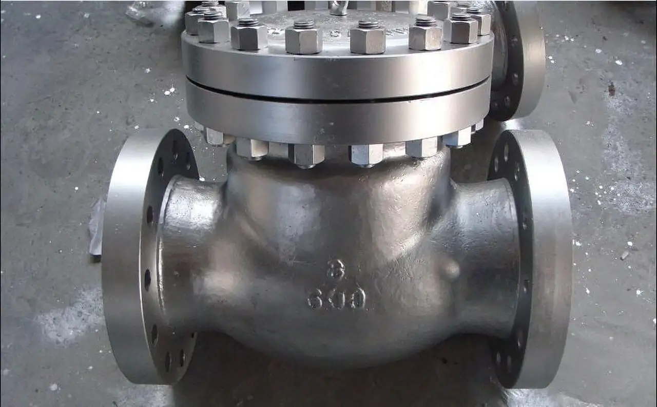
A lift check valve is a self acting check valve built on a globe style body: a disc or piston, guided on a stem or inside a cage, seats over a seat ring on the flow axis and lifts straight off it when forward flow pushes, then drops back under gravity and reverse flow when the column tries to reverse. The travel is short, a few millimeters, so the closure member gets home before the reversing column gathers speed, which is the whole engineering argument for the type: fast, centered, low slam closure in exchange for a somewhat higher pressure drop than the hinged alternatives. Bodies run from DN 15 to DN 600 with bolted bonnets at Class 150 to Class 600, and continue into pressure seal bonnet constructions at Class 600 through Class 2500 for power plant feedwater, boiler feed, and steam header duty. Plant vocabulary says piston lift check for the guided piston builds and globe lift check for the disc builds; this page treats them as one family and sorts them properly.
Procurement engineers meet these valves on boiler feedwater and condensate return lines, on saturated and superheated steam headers, on pump discharge protection where slam would fatigue the piping, and on clean process liquids where a guided closure member is acceptable insurance. The decision this page settles is narrow and practical: which body architecture, bolted bonnet or pressure seal, which disc style, guided piston or guided disc, whether a spring assist belongs in the trim, which flow orientation the installation actually has, and what test evidence the quotation must carry. The answer lands as an RFQ line set tested per API 598, and every chapter below feeds that line set so the non return function is bought on evidence rather than on a flow arrow and hope.
This page treats the lift check valve as a purchasing object: how the guided disc and the piston trim actually close, what separates bolted bonnet from pressure seal construction, where Y-pattern bodies earn their cost in steam, what cracking pressure and seat velocity numbers belong in the datasheet, and how all of it combines into a defensible RFQ. It is written for engineers who issue purchase specifications, not for readers who want a brochure summary.
Chapter 1 / 06
What a Lift Check Valve Is and What Is Being Decided
The guidance is the definition. Every check valve answers one question: flow one way yes, flow the other way no. The lift type answers it with a closure member that moves along the flow axis, held on course by a stem guide or a cage, and that is the difference the buyer is paying for. A hinged disc on a swing type sweeps an arc and slaps its seat when the column reverses; a guided disc or piston travels a few millimeters on the axis and lands centered, every time, with its load spread over the guiding surfaces instead of concentrated on one hinge pin. The body that carries this trim is a globe valve architecture, with the same bolted bonnet, the same globe style flow turn, and the same seat ring logic, minus the stem, packing, and operator: a check valve that never needs a human to close it, and never can be closed early by one either.
What is actually being decided in this purchase is a set of six commitments made in one line set. First, a body architecture commitment: bolted bonnet for Class 150 to Class 600 general duty, pressure seal bonnet for Class 600 through Class 2500 power and steam service. Second, a trim commitment: guided piston or guided disc, with or without a soft insert on the seat. Third, a spring commitment, because a spring assist changes cracking pressure, closure speed, and the orientations the valve can serve. Fourth, an orientation commitment, horizontal or vertical up flow, which many designs answer differently and some answer not at all. Fifth, an ends and materials commitment: flanged or butt weld, body and trim grades against the chemistry and temperature. Sixth, an evidence commitment: shell and seat testing per API 598 with the leakage acceptance stated. A quotation that answers only size and class has quoted a casting with an arrow on it, not a non return device.
Against its neighbors the type occupies deliberate ground, and the full comparison belongs in the selection chapter. The small bore forged piston family, the compact DN 15 to DN 50 builds covered by the piston check valve page elsewhere in this encyclopedia, shares the lift principle in a screw-ended or socket welded body; this page covers the flanged and welded globe body family that scales into power plant sizes. The swing check valve dominates large bore water on price and pressure drop, the dual plate check valve compresses that duty into a wafer body, the tilting disc check valve adds speed on water mains, and the axial flow check valve is the premium anti slam instrument on critical pump discharges. At the small dirty end, a ball check valve tolerates what a guided trim cannot. This page is the clean liquid and steam specialist of that lineup: the type that closes fastest per dollar of guided precision, and the one that must not be bought for solids bearing service at all.
Four standards organize the datasheet, with two more in support. ASME B16.34 governs wall thickness and the pressure temperature ratings by class and material group, the frame every quoted rating hangs on. API 598 defines the inspection and test regime, shell hydrostatic test and seat test with the acceptance criteria the factory certificate should name. FCI 70-2 defines the leakage classes quoted for soft seated constructions, class VI being the bubble tight reference buyers usually want in a soft insert. Face-to-face and end-to-end dimensions follow ASME B16.10 so one maker's body drops into another's spool gap, flange drilling follows ASME B16.5, and the bolted bonnet architecture itself shares design context with the API 600 and API 602 valve families it descends from. A datasheet that quotes none of these is a price tag, not a specification.
The RFQ should also state the station, because a check valve never arrives alone. On a pump discharge it sits with an isolation gate valve or ball valve downstream for maintenance access, and the loop it protects is the pump against reverse rotation and the piping against slam. On steam duty it shares the work order with the steam trap stations that drain the low points during warmup, so the disc is not hit by a condensate slug at startup. On feedwater it pairs with the globe control valve or recirculation hardware that manages low flow, where the check holds the header while the control element does the throttling this valve cannot. Stating the station in the RFQ lets one supplier check flange drilling, gasket, face-to-face, and orientation compatibility across the package in a single pass instead of four arguments at delivery.
Chapter 2 / 06
How the Guided Disc Lifts and Seats
Mechanically the trim is a poppet. Forward flow approaches the seat ring, and the dynamic pressure of the fluid acting on the exposed disc area overcomes the disc weight, the guide friction, and the spring force if one is fitted; the disc lifts along the axis and the flow passes through the annular opening it creates. The travel is deliberately short, a small fraction of the bore, commonly a few millimeters even at DN 100, and the guided member reaches a stable full lift position where the flow holds it open without hunting. The seat port in a globe style body usually runs smaller than the pipe bore, which is why these valves carry a somewhat higher pressure drop than hinged types: the body is trading a pressure loss figure for a centered, repeatable seal and a closure distance measured in millimeters.
Closure dynamics are where the type earns its money. When the pump trips or the header reverses, the decelerating column tries to flow backward through the seat; the pressure across the disc reverses, and the disc travels its few millimeters home while the column is still slowing down, so it lands with the reverse velocity across it close to zero. Slam energy in a check valve grows with the mass of the closure member and the square of the velocity it is carrying at impact, which is the physics that makes a long travel hinged disc loud and a short travel guided disc quiet. That is the honest trade: the lift type accepts a higher running pressure drop in exchange for landing centered at low impact speed, and on boiler feed and condensate duty that trade is usually correct, because fatigue in those systems is expensive in a way a tenth of a bar never is.
The spring decides whether the physics works at all in vertical lines and at low flows. Gravity seats a horizontal disc nicely: no spring strictly needed, and some designs ship without one. Vertical up flow inverts the logic, the disc would have to fall upward to close, so a spring is mandatory and the valve must be built for that duty from the start. Spring assist also raises the cracking pressure, the forward differential needed to open the trim at all: typical published values run 0.05 to 0.35 bar for spring assisted builds, and the number belongs in the datasheet because a low head transfer system can be stalled by a cracking pressure chosen for another service. Spring material is a purchase line too: 316 stainless covers water and steam family duty, and Inconel X-750 class alloys cover the high temperature ends.
The sizing numbers a specification meeting actually argues about are seat velocity and pressure drop. Guidance commonly quoted across manufacturer literature puts the velocity at the seat in the 2 to 5 m/s band at rated flow for good behavior: fast enough to hold the disc full open and stable, slow enough not to wire draw the seat land in service. Below that band the disc floats and hunts, above it erosion and noise start buying themselves. The pressure drop at rated flow for a properly sized body typically lands in the 0.2 to 0.8 bar range, and a quotation claiming dramatically less from a globe style body is quoting a different geometry or an honest mistake. The Y-pattern body exists precisely to buy some of that drop back: by angling the seat port toward the line axis it straightens the passage for steam and condensate service, and the selection chapter prices that option properly.
Chatter is the failure mode that size errors create. An oversized check valve lives half open, its disc bouncing on the turbulence because the flow never develops enough velocity to hold it full lift; the guide takes the impacts, the seat takes the seating strikes, and both wear at rates the catalog never printed. The same valve sized so normal flow sits in its stable band runs quiet for decades. This is why the RFQ should state the actual normal and maximum flows rather than the pipe size alone: the supplier is being asked to confirm stable lift, not merely to fit the bolt holes.
Water hammer closes the physics chapter, because the loud check valve failure everyone remembers is a system failure wearing a valve costume. Sudden closure of any check valve can raise pressure when a fast moving column is stopped against it; the lift type minimizes its own contribution by closing before reversal, but if the piping is mis-sized, if the pump trip is abrupt, and if there is no relief path for the deceleration transient, the resulting surge belongs to the system, not to the trim. The engineering sequence is honest: size the check valve for stable lift, size the piping for the deceleration transient, and leave overpressure protection to the safety relief valve on the segment, which is the device actually built for that question. A check valve of any type is not a pressure relief instrument and must never be specified as one.
Chapter 3 / 06
Types, Construction, and Duty Boundaries
The family sorts by body architecture first. The horizontal bolted bonnet piston lift check is the workhorse: a straight globe body, guided piston trim, bonnet bolted and gasketed, made in Class 150 to Class 600 and commonly to DN 600 at the lower classes. The bolted bonnet is a maintenance feature as much as a pressure feature: the trim is reachable with the valve out of the line or, on many builds, in place with the upstream spool drained, the guide and seat ring renew without cutting, and the body gasket is a standard purchase. For plant water, condensate, utilities, and clean process liquids, this is the build the majority of purchase orders should name.
The Y-pattern body tilts the seat port into the line axis, typically at about 45 degrees, so forward flow makes one turn instead of two. The pressure drop falls noticeably, the disc still lifts and lands on its guide axis, and the construction suits steam and condensate duty where every tenth of a bar of irreversible loss across a check station is heat and money. Y-pattern lift check builds exist precisely for this duty, and the honest RFQ for saturated steam, condensate return, and turbine extraction lines should ask for the Y-pattern option and its drop figure by name rather than accept a straight body because it was in stock.
The pressure seal bonnet is the high class, high temperature architecture. Above about Class 600, bolted joints grow studs and gaskets faster than sense, so the bonnet is pushed into a tapered seat by internal pressure itself: the higher the pressure, the harder the seal ring grips, with a small retained segment or shear ring taking the bonnet load instead of a stud circle. Pressure seal lift check valves in this class carry boiler feedwater, feed heater drains, and main and auxiliary steam headers in power plants at Class 600 through Class 2500. The trade is maintenance access, because the bonnet comes apart under a procedure, and thermal cycling patience, a failure mode chapter 6 treats properly.
The small end of the family has its own page and its own products, and the boundary should be stated plainly. The piston check valve page in this encyclopedia covers the compact forged small bore family, DN 15 to DN 50, screw ended or socket welded, often Class 800 or Class 1500, the piston lift principle in a body you hold in one hand; this page is the flanged and butt welded globe body family from DN 15 upward. Where the two overlap in size, the choice is installation driven, threaded and welded compact versus flanged maintainable, not function driven. Below that, a ball check valve seats a free ball against an angled seat and tolerates small solids that would hang a guided trim, and at the suction end of a pump the foot valve is the submerged inlet check whose strainer screen and primer duty belong to that page. None of those neighbors needs to be quoted as this page's product, and none of them substitutes for it in steam.
Duty boundaries deserve blunt statements, because guided trim is regularly misapplied by catalog shoppers. Not for solids bearing service: a guided piston hates sand, scale, and fiber, which jam the guide clearance and hold the disc off its seat, and slurry duty belongs to other valve families entirely. Not for throttling: this is a full open or closed device, and any station that must regulate flow needs a globe control valve or another modulating instrument beside it, never this trim in a half position. Not a substitute for isolation: maintenance access wants a gate valve or a ball valve in series, and at large bore in water service a butterfly valve carries that isolation economically where class allows, because a check seat is a flow logic device, not a locked boundary. And not a safety device: overpressure protection stays with the safety relief valve and, on the vent side, with the hardware built to vent. The lift check valve is a clean fluid, steam and feedwater specialist, and it should be bought as one.
The type map below consolidates the family into one table a specifier can scan before writing the RFQ.
Boiler feedwater, main steam, heater drains, power duty
Compact forged piston check
Small forged body, screwed or socket weld ends
DN 15 to DN 50, Class 800 to 1500 typical
Small clean lines, covered by the piston family page
Spring assisted vertical service
Body built for up flow, spring mandatory
Per build, stated in RFQ
Vertical risers where no horizontal run exists
Chapter 4 / 06
Key Specification Parameters
The table below decodes the datasheet lines that decide whether a quoted valve matches the duty. Each row is purchase defining; the paragraphs after the table explain what to demand and what a weak answer looks like.
Attribute
Typical range or options
What it decides
Nominal size
DN 15 to DN 600 flanged and welded family
Spool length, seat velocity band, and stable lift point
Pressure class
Class 150 to 600 bolted bonnet; Class 600 to 2500 pressure seal
Body architecture, rating per ASME B16.34, bonnet serviceability
Ends
Flange RF per ASME B16.5, or butt weld per schedule
Installation method, face-to-face per ASME B16.10, gasket scope
Disc style
Guided piston or guided disc, with or without soft insert
Leakage class, reseating behavior, and wear surface area
Spring assist
None, or spring with 0.05 to 0.35 bar cracking pressure
Orientation capability, closure speed, and low flow behavior
Orientation
Horizontal standard; vertical up flow only when built for it
Whether the valve closes at all in the installed position
Body and bonnet materials
WCB or WCC, CF8M, WC6 and WC9 alloy for hot service
Temperature window, creep and graphitization limits, chemistry
Trim and seat
13Cr trim standard, hardfacing optional, PTFE or EPDM insert optional
Wire drawing resistance in steam and the leakage acceptance
Spring material
316 stainless; Inconel X-750 class at high temperature
Spring fatigue life at the service temperature
Test evidence
Shell and seat test per API 598, leakage class stated
Whether the non return claim was ever verified at pressure
The materials row deserves its own paragraph because steam divides it sharply. Carbon steel WCB and WCC bodies carry water, condensate below the creep band, and utility duty to the limits of the ASME B16.34 tables, with the classic caution that carbon steel loses credibility in long term service above about 425 deg C where graphitization begins. The chrome moly alloys WC6 and WC9 carry the 400 to 590 deg C band that feedwater and steam duty actually lives in, and any supplier quoting carbon steel into that band should be rejected on the spot. CF8M stainless covers clean, corrosion, and cryogenic adjacent duty, with LF2 and LF3 class forgings handling the low temperature carbon steel range where impact tested material is required. Trim runs 13Cr stainless as the default, with hardfacing on the seat land where high differential steam will wire draw bare metal, and the soft insert option buying FCI 70-2 class VI bubble tight seating in water and condensate at moderate temperature.
The performance numbers belong in the datasheet as numbers, and the table below collects the ones a specification meeting will actually cite.
Parameter
Typical value or band
How to use it
Cracking pressure, spring assisted
0.05 to 0.35 bar typical
Check against the lowest credible forward flow differential at the station
Velocity at seat, rated flow
2 to 5 m/s guidance band
Confirm normal flow holds the disc at stable full lift
Pressure drop at rated flow
0.2 to 0.8 bar typical for the family
Compare with Y-pattern quote where steam energy is money
Seat leakage acceptance
API 598 seat test; FCI 70-2 class VI where soft seated
Name the class in the purchase order, not after delivery
Shell test
Hydrostatic per API 598 and ASME B16.34 practice
Factory certificate states test pressures and acceptance
The orientation row is the one that quietly voids warranties. Many horizontal lift check designs rely on gravity to seat the disc and simply do not close when installed with the axis vertical; the vertical service builds exist, they carry a spring and an internal architecture designed for up flow, and they say so on the nameplate. Down flow in a vertical line is not a service any lift trim offers, because neither gravity nor spring can be made to close against the flow direction. The RFQ must state the installed orientation and the flow arrow direction in words, and the returned datasheet must state the orientation the valve is built for; when those two lines disagree, the order stops there.
The ends row closes the specification. A flange connection per ASME B16.5 raised face drilling keeps the valve serviceable with standard gaskets, a spiral wound gasket with inner ring by class practice, and studs brought up under ASME PCC-1 discipline; butt weld ends eliminate the gasket joint and the leak statistics that come with it, at the price of trim access requiring a cut or a spool removal. Face-to-face per ASME B16.10 keeps the body interchangeable between makers when the day comes. End standards and gasket practice are the same as any flanged globe valve station on the same line class, which is why the maintenance crews treat the two bodies as one family on the walkdown. The quotation should state which gasket scope it assumes, because a flanged valve quoted without its gasket is a Monday morning surprise, and the walkdown that finds the wrong gasket on a steam line is never a calm one.
Chapter 5 / 06
Selection Decision Factors and RFQ Language
The decision sequence is short enough to run as a checklist in a specification meeting, and each step eliminates a class of quotations before price comparison starts.
Define the fluid honestly, including solids, scale, and chemistry: guided lift trim is a clean fluid instrument, and any solids loading moves the station to other families immediately.
Fix the duty: feedwater, condensate, steam header, or clean liquid pump discharge, because the duty sets the body architecture and the material group, not the other way around.
Fix size against the 2 to 5 m/s seat velocity guidance at normal flow, not against the pipe size alone, and demand the stable lift confirmation from the supplier.
Choose the architecture: bolted bonnet to Class 600, Y-pattern where steam energy justifies the drop savings, pressure seal from Class 600 into power service.
Choose the trim: guided piston or disc, hardfaced seat land for high differential steam, soft insert where bubble tight water duty and moderate temperature allow.
Set the spring: none for horizontal gravity seating, mandatory for vertical up flow, cracking pressure 0.05 to 0.35 bar confirmed against the station's lowest forward differential.
State orientation in words, with the flow arrow, and reject any datasheet that answers a different orientation than the installation.
Fix the evidence: shell and seat test per API 598, leakage class named, material certificates EN 10204 3.1, and the pressure temperature basis per ASME B16.34.
Against neighboring check valve types the comparison a specifier actually needs runs as follows, and it belongs here in the selection chapter rather than in the page title. The swing check valve wins large bore water on purchase price and low pressure drop, pays for it with longer travel and louder closure, and suits buried water mains and cooling water where slam is tolerated. The dual plate check valve compresses that same duty into a wafer body a fraction of the length, with twin spring closed plates that beat the swing disc on closure speed at modest cost. The tilting disc check valve adds a spring assisted fast disc to large water service and is the classic power house circulating water answer. The axial flow check valve is the premium instrument: a center guided, spring loaded disc moving on the line axis with the lowest slam of the family, bought for critical pump discharges and pipelines where surge analysis drives hardware. The lift type holds its ground where guided precision and repeatable centered seating pay: feedwater, condensate, steam headers, and clean process liquids at moderate to high class, which is exactly the territory this page specifies. Choose the mechanism the station needs, not the type the distributor stocks.
The isolation and throttling neighbors answer different questions and should be specified alongside, not instead. Operations and maintenance access wants a gate valve or a ball valve in series with any check station, and a butterfly valve economically covers large bore isolation where class allows. Throttling belongs to the globe control valve or another modulating instrument, never to a trim that must sit full open to be healthy. On steam stations the steam trap drains the low points so warmup does not launch a slug at the disc, and the walkdown checks both devices in one pass. On the suction side, the foot valve on the wet well keeps the pump primed while the discharge check protects it, and the Y strainer upstream of the whole skid catches the commissioning debris that would otherwise seat itself in the first guide clearance it finds. Overpressure protection on the segment stays with the safety relief valve, whose duty no check valve borrows.
The application map below turns the rules into a table the project file can carry.
Application
Construction to specify
Check before order
Boiler feedwater, Class 900 and above
Pressure seal body, WC6 or WC9, guided piston, hardfaced seat
Cracking pressure against low load recirculation differential
Condensate return header
Y-pattern bolted bonnet, WCB or CF8M, soft insert optional
Seat velocity at condensate flow, not at boiler feed flow
Saturated steam distribution
Y-pattern, WC6 class by temperature, hardfaced seat land
Pressure drop quoted at steam density, orientation stated
Pump discharge, clean liquid, Class 150 to 300
Horizontal bolted bonnet piston lift, spring assisted
Stable lift confirmation and slam expectation versus piping study
Vertical riser, up flow
Vertical service build with spring, stated by maker
Insert temperature limit against service, leakage class named
The RFQ block should be written once and reused. A complete block reads: quantity; size DN; class; body architecture, bolted bonnet, Y-pattern, or pressure seal; ends, flange RF or butt weld, with face-to-face per ASME B16.10 and drilling per ASME B16.5; body, bonnet, trim, and spring materials with the EN 10204 3.1 certificates; disc style, guided piston or guided disc, with insert and hardfacing options named; spring assist yes or no with the cracking pressure value; installed orientation and flow arrow in words; normal, maximum, and minimum flow with temperature and pressure so the supplier confirms stable lift in the 2 to 5 m/s band; pressure drop expectation at rated flow; test regime, shell and seat per API 598 with the leakage class stated; and the pressure temperature basis per ASME B16.34. A quotation returned without the orientation statement or the test evidence is incomplete at any price.
Chapter 6 / 06
Installation, Standards, Failure Modes, and Maintenance
Installation quality decides whether the trim reaches its catalog life. Set the body with the flow arrow matching reality, checked by two people, because reversed check valves pass nothing and half the world has a story about it. Keep the axis within the orientation the nameplate allows, horizontal designs horizontal, vertical service builds pointing up, and give the valve a few pipe diameters of straight run off elbows and pumps, less for the disc than for the flow profile that holds it stable. A flange joint gets its gasket, spiral wound with inner ring by class practice, centered inside the bolt circle and brought up in cross pattern passes under ASME PCC-1 discipline; a butt weld joint gets a procedure and a heat treatment plan, and the walkdown checks both. Leave bonnet access clear, because the day the trim needs attention, the access design is the difference between an afternoon and an outage.
Commissioning practice protects the guide clearances, which are the precision of the whole product. Flush and blow the lines before first flow, keep the Y strainer in service through the debris season, and expect to clean it more than once, because weld bead and scale are guided trim's worst enemies and they all arrive in the first month. On steam service, warm the line through the bypass or the trap stations slowly: the steam trap drains the condensate that would otherwise hit the disc as a slug, and the valve enters service dry, hot, and unstressed. Record the first week of listening, because a healthy lift check is quiet, and that quiet baseline is what the maintenance walkdown compares against for the next decade.
The standards set the verification frame. ASME B16.34 fixes the wall thickness and pressure temperature ratings by class and material group, the numbers every quotation leans on. API 598 defines the inspection and test regime, shell hydrostatic and seat test with acceptance the certificate names. FCI 70-2 defines the leakage classes for soft seated constructions. ASME B16.10 fixes face-to-face interchange and ASME B16.5 the flange drilling, and ASME PCC-1 governs the bolted joint assembly that seals them. The bolted bonnet architecture shares design context with the API 600 and API 602 families it descends from, which is why material and casting practice questions have well worn answers. A specification that cites the standards by name in the RFQ block transfers the burden of proof to the supplier, which is where it belongs.
Failure modes in service follow a short and predictable list. Disc guiding wear: the guide clearances open up, the disc lands off center or floats at low flow, audible as chatter and measurable as rising reverse leakage, remedied by trim renewal at the first drift signal rather than after the seat has hammer marked itself. Spring fatigue in spring assisted designs, seen as rising cracking pressure and sluggish closure, most often when a spring material was stretched past its temperature band by a quiet substitution. Pressure seal gasket leak on thermal cycling, the pressure seal architecture's own signature, where repeated heating and cooling relaxes the seal ring load and a weep appears at the bonnet joint, corrected by the maker's re-seating procedure at the next cool down. Seat wire drawing, the erosion thread cut through a seat land by high differential steam flashing across a small leak path, which is why hardfacing belongs in the hot steam specification and why a weeping check valve on steam is a repair item this month, not next year. And water hammer from sudden closure events, which the short travel minimizes but cannot abolish if the piping was mis-sized around it: the damage lands on the piping and the guide alike, and the fix belongs in the surge study, not in a heavier valve. None of these modes hides from a listening walkdown, which is the point of having one.
Maintenance intervals scale with duty severity, and most of the program is ears and paperwork. The routine walkdown listens for chatter and checks the station for weep at the bonnet and the flange joints; the annual outage adds a reverse leakage observation against the baseline and a strainer element inspection. Feedwater and steam duty at high class earns an internal inspection at every major turnaround, seat land and guide clearances measured against the maker's wear limits, spring free length checked, soft inserts renewed as consumables. The seat that has wire drawn gets lapped or replaced on evidence, not on calendar. And the file discipline pays twice: the datasheet that stated orientation, cracking pressure, and test evidence at purchase becomes the specification the replacement is checked against, which is how a purchasing file gets smarter instead of just older.
FAQ
What is the difference between a lift check valve and a swing check valve?
The closure member and its path. A lift check valve guides a disc or piston on the flow axis over a seat ring, traveling a few millimeters, so it lands centered at low impact speed and suits feedwater, condensate, and steam in globe style bodies. A swing check valve hinges a disc through an arc, with lower pressure drop and price at large bore in water service but more slam energy. Choose lift for guided precision on clean fluids and steam.
Can a lift check valve be installed in a vertical line?
Only when the valve is built for vertical up flow, and the nameplate must say so. Horizontal designs rely on gravity to seat the disc and will not close on a vertical axis. Vertical service builds exist with a spring that closes the trim and the internal architecture to guide it, and they must be ordered by stating the orientation in words. No lift check design of any make serves vertical down flow, because neither gravity nor spring can close against the flow direction.
What is cracking pressure and how do I specify it?
Cracking pressure is the forward differential needed to open the trim off its seat, typically 0.05 to 0.35 bar for spring assisted lift check designs, and near zero for horizontal gravity seated builds. Specify it against the lowest credible forward flow differential at your station: a transfer driven by a few meters of head can be stalled by a spring chosen for another service. State the value in the RFQ and require the supplier to confirm it on the returned datasheet with the spring material named.
Should I order a bolted bonnet or a pressure seal body?
Class and temperature decide. Bolted bonnet bodies serve Class 150 through Class 600 general duty, give simple trim access through a standard gasketed joint, and cover most industrial water, condensate, and process service. Pressure seal bodies take over from about Class 600 into Class 2500 power and steam duty, where the bonnet seal grips harder as pressure rises and the stud circle disappears. The trade is maintenance access and thermal cycling patience, so power plant feedwater and steam headers earn pressure seal, and everything below it usually does not.
Why does my lift check valve chatter in service?
Chatter means the disc is not reaching stable full lift, and the usual cause is oversizing: normal flow sits below the 2 to 5 m/s seat velocity band the trim wants, so the disc floats and bounces on turbulence. The guide clearances take the impacts and open up, which makes the chatter worse and eventually leaks. Check the actual normal flow against the maker's stable lift range before blaming the valve. Guiding wear from earlier debris service produces the same symptom and wants a trim inspection.
Are lift check valves suitable for slurries or dirty fluids?
No. The guided piston and guided disc trims run with close clearances that solids jam, and sand, scale, or fiber holds the closure member off its seat or scores the guide until reverse leakage is permanent. Slurry and solids bearing service belongs to other valve families selected for that duty. Keep commissioning debris away with line flushing and a strainer upstream, because the first month of weld bead is guided trim's worst enemy even on nominally clean systems.
What does Y-pattern mean and when is it worth the premium?
A Y-pattern body angles the seat port toward the line axis, typically about 45 degrees, so flow makes one turn instead of two through the valve. The pressure drop falls noticeably, the guided disc keeps its centered, low slam closure, and the construction suits saturated steam, condensate return, and extraction lines where every tenth of a bar lost across a check station is heat and money. It is worth the premium when the energy arithmetic over service life exceeds the price difference, which on continuous steam duty it usually does.