A pressure exchanger is an isobaric rotary energy recovery device fitted to reverse osmosis trains. A precision ceramic rotor, drilled with parallel ducts, turns slowly, about 1,200 to 3,000 rpm in the established families, inside a close-clearance sleeve, and each duct alternately opens to the high-pressure brine reject stream and to the low-pressure feed water. Because the brine hands its hydraulic energy directly to the feed across a moving liquid interface, with both streams at essentially the same pressure, the transfer runs at 92 to 96 percent efficiency, and the electric motor only has to make up clearance leakage, viscous shear, and a small mixing allowance. One module passes tens of cubic meters per hour of brine, and arrays of 2 to 12 and more modules cover a full train.
Procurement engineers meet the pressure exchanger on seawater reverse osmosis duty, where brine leaves the membranes at 55 to 70 bar and would otherwise throttle to waste, and increasingly on brackish water and wastewater RO arrays pushed to high recovery. The decision this page settles is narrow and practical: how much of the membrane feed reaches full pressure through recovered brine energy instead of motor power, how many rotor modules the train flow needs, what filtration protects the ceramic sealing surfaces, and which porting materials survive seawater chloride service. The answer lands as an RFQ line set: service and recovery window, brine and feed flows, pressure limit, filtration rating, materials, booster pump pairing, array count, and the efficiency claim basis the supplier must guarantee.
This page treats the pressure exchanger as a purchasing object: the ceramic rotor mechanics behind the isobaric claim, the mixing and lubrication arithmetic that sizes the booster pump, the array logic that matches module count to train flow, the chloride-service materials that decide service life, and how all of it is written into an RFQ with a defensible efficiency guarantee. It is written for engineers who issue purchase specifications, not for readers who want a brochure summary.
Chapter 1 / 06
What a Pressure Exchanger Is and What Is Being Decided
The defining hardware is the rotor and sleeve assembly. A cylindrical ceramic rotor, high-grade alumina or zirconia, is drilled with a ring of parallel axial ducts around its circumference. It spins inside a fitted sleeve whose end faces are ported: one port plate arc connects duct ends to the high-pressure brine circuit, another arc connects them to the low-pressure feed circuit, and sealed lands between the arcs keep the two circuits apart. As the rotor turns, each duct is alternately charged with low-pressure feed, swept into the high-pressure arc, displaced by incoming brine at full membrane pressure, and swept back to discharge. The device is a rotary displacement contactor: four connections, low-pressure feed in, high-pressure brine in, high-pressure feed out, low-pressure brine out, and a small motor whose only job is to spin the rotor against fluid friction.
What is actually being decided in this purchase is the energy balance of a reverse osmosis train. On a seawater plant, roughly half of the pumped feed leaves the membranes as brine at almost the same pressure it entered, and every kilowatt-hour spent pressurizing it is either recovered or throttled to waste. The isobaric pressure exchanger recovers that energy by direct displacement, so the high-pressure centrifugal pump shrinks from carrying the whole feed to carrying only the permeate-plus-mixing fraction. The buyer therefore commits to four things at once: the array count and module size that pass the train flow, the booster pump that trims the recovered stream back to membrane pressure, the filtration stage that protects the ceramic sealing surfaces, and the porting materials that survive chronic chloride exposure. A quotation that answers only "energy recovery device, 95 percent" has answered none of the four.
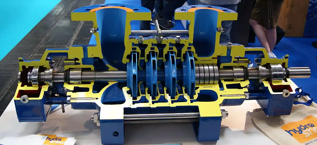
The high-pressure pump paired with the exchanger deserves its own sentence in the specification. It is a multistage pump of the ring-section or barrel architecture, the same family tree as the boiler feed pump on a steam plant, but selected for seawater duty: superduplex or duplex hydraulic sections, low NPSH first stage, and a mechanical seal suited to 60 bar-class salt water. It is not a general service machine with a marine coat of paint, and the specification for the package should state the pump duty explicitly because the exchanger changes what the pump must do. Where feed temperature swings seasonally and upsets membrane productivity, a plate heat exchanger on the seawater feed stabilizes the inlet condition, and the antiscalant injected by a small metering pump protects both membranes and exchanger ports from scale. A silica analyzer on the raw water line catches the scaling risk before it deposits, which matters because carbonate and sulfate scale in rotor ports is a removal event, not a cleaning event.
Boundaries should be stated plainly at the start. The pressure exchanger is not a pump: it multiplies no pressure, creates no head, and cannot lift the feed one bar; it only exchanges pressure between two liquid streams that already exist, so the high-pressure pump and the booster remain essential. It is also not the only energy recovery architecture on the market. Pelton wheel turbines and pressure turbochargers are the neighbor technologies, older and still built, and the honest differences between the three families belong in the selection chapter where the duty decides, not in the page title. This page covers the isobaric rotary family specifically, the PX device class used on the majority of new seawater trains, and it does not attempt to be an umbrella page for every energy recovery device on the market.
Duty windows frame the purchase. Seawater reverse osmosis trains run the family range from roughly 40 to 50 percent recovery, brackish and process water arrays run higher, and high-recovery wastewater RO designs push toward the very high nineties where nearly everything leaving the membranes is brine and the exchanger carries almost the whole feed. Working pressures span the 55 to 70 bar seawater band with family maximums of 80 to 120 bar by model, and brine specific gravity moves with salinity, which shifts both the hydraulic balance and the mixing consequence. The exchanger is bought against those three numbers together: recovery, pressure, and salinity, and any of them quoted alone makes the sizing arithmetic unverifiable.
Standards context is thinner here than for valves or pumps, and the honest specification says so. No single ISO product standard covers the isobaric rotary pressure exchanger; the defensible references are the pressure part codes applied to the porting and manifolds, ASME boiler and pressure vessel code practice where the site demands coded parts, the material specifications behind the wetted alloys, ASTM B625 for superduplex plate and ASTM B165 for nickel alloy tubing in the family's peripheral piping, ANSI/ASME flange dimensions at the ports, and the OEM performance guarantee with its stated test basis. The datasheet row that matters most is therefore contractual rather than normative: what efficiency, at what flows, at what salinity, proven how. A supplier who will not state the basis is quoting a percentage, not a machine.
Chapter 2 / 06
How the Isobaric Rotor Transfers Brine Energy
Follow one duct through a revolution. In the feed arc, the duct fills with low-pressure filtered seawater at a fraction of a bar. As rotation carries it under the high-pressure port, brine at full membrane pressure enters the same duct from the other end and drives the feed out ahead of it. Because the two liquids are in direct contact inside the duct, with a short mixing zone whose thickness is set by residence time and rotor speed, the feed leaves at essentially brine pressure, typically 2 to 3 bar below it after clearance and shear losses. Rotation continues, the duct sweeps to the low-pressure discharge arc, the spent brine exits toward the outfall at near-atmospheric pressure, the duct refills with feed, and the cycle repeats. Several ducts are always in each phase, so the flow at all four connections is continuous, and the pulsation at package level is mild, which is why the plumbing around an exchanger array is compact for the power it moves.
The efficiency mechanism is the whole point of the architecture. A Pelton wheel converts brine pressure to shaft power and back to pump pressure, paying twice for each conversion; a pressure turbocharger couples the streams through one rotating set and pays once; the isobaric rotor skips the conversion entirely and hands momentum from one liquid column to another through displacement. What is left as loss is a short ledger: viscous friction on the rotor and sleeve, leakage across the running clearances from the high to the low side, and the mixing that crosses the interface. That ledger lands at 92 to 96 percent hydraulic transfer efficiency for the established families, and the loss items are exactly the ones a commissioning test can verify in the field.
Mixing is the parameter buyers under-specify. As the feed-brine interface passes along each duct, a boundary layer exchange sends 1 to 3 percent of the brine salinity into the feed stream in the family norm. The consequences run two ways. First, membrane feed salinity rises slightly, which lowers permeate quality and raises osmotic pressure a fraction of a bar; on a seawater train the permeate conductivity meter reads the result, and plants with tight permeate targets ask for the vendor's mixing figure at their salinity and temperature, not the catalog value at standard seawater. Second, the mixing flow is a real volume that has to be accounted: it arrives with the recovered stream, so the booster pump flow must include it, and the lubrication bleed must be added beside it. A quotation whose booster flow equals the recovered stream exactly has forgotten 2 to 3 percent of the arithmetic.
The circuit arithmetic is worth writing out because it is the heart of the RFQ. Take a modest train delivering 100 m3/h of permeate at 45 percent recovery and 62 bar: feed is about 222 m3/h and brine about 122 m3/h. Without recovery, the high-pressure pump lifts all 222 m3/h from 2 to 62 bar, and the train pays for every cubic meter twice, once going in and once throttling out. With an exchanger array, the high-pressure multistage pump carries only about 103 m3/h, the permeate flow plus the mixing and lubrication allowance, to full pressure. The brine stream hands 119 m3/h of feed back at roughly 59 to 60 bar, and a small booster pump, often a two or three stage machine on a VFD, trims those 119 m3/h the final 2 to 3 bar into the membrane header. The specific energy of the train falls from the 3.5 to 4.5 kWh per m3 class of unrecovered designs toward the 2.0 to 3.0 class, with the exact figure set by intake conditions, recovery, and pump efficiency. Those two saved kilowatt-hours per cubic meter are the entire business case, and they pay for the array in one to three years at industrial power prices.
The rotor drive and the lubrication flow complete the mechanism. The drive motor is fractional against the energy flowing through the machine, sized to overcome bearing and fluid friction, typically a few kilowatts per module. The lubrication flow is deliberate: a small fraction of low-pressure feed, about 1 to 3 percent, is routed across the sleeve faces to keep the ceramic running surfaces separated and cool, set by a needle valve or fixed orifice in the skid and monitored so its loss trips an alarm before it scores the sleeve. Because the rotor and sleeve are precision ground ceramics, the filtration ahead of the exchanger is not optional: the family requirement is a cartridge stage in the 10 to 100 micron class, and the vendors' manuals are blunt that grit, weld bead, or construction debris through the ports is the fastest way to buy a new rotor.
Sound and controllability close the operating picture. An exchanger array is a quiet hum punctuated by piping noise, with family sound levels in the mid 70s to high 80s dB(A) at one meter depending on array size, pressure, and enclosure, modest next to the high-pressure pump beside it but not negligible in a containerized plant. Control is architectural rather than throttled: the exchanger has no setpoint, no stroke, and no trim of its own; capacity follows the flows imposed on it, and the plant controls the booster and the high-pressure pump, which is why the booster on a VFD is the standard actuator for holding membrane pressure against feed temperature and demand swings. That absence of an internal control loop is a purchasing advantage: there is no control valve, no positioner, and no characterization curve to maintain inside the recovery circuit.
Chapter 3 / 06
Types, Construction, and Duty Boundaries
The single-rotor module is the atom of the family. Its wetted core is the ceramic rotor and sleeve, alumina in the long-established builds and zirconia where higher toughness is wanted against thermal or impact shock, surrounded by a steel pressure housing with the port connections. The porting and manifold hardware is where seawater experience shows: superduplex 2507 or super austenitic 6Mo alloys are the family standard for chloride service, carbon steel appears only on brackish, low chloride duties, and the elastomers in the static seals are EPDM family compounds checked against the chemical dose in the feed. A module of the established classes passes roughly 17 to 60 m3/h of brine, with the large-duct, Q400-class modules at the top of that span, and carries nameplate pressures in the 80 to 120 bar family maximum.
Arrays are how trains are covered. Because one module cannot pass a utility train's brine flow, the family is installed as 2 to 12 and more identical modules manifolded in parallel on a common brine inlet, low-pressure feed inlet, high-pressure feed outlet, and brine reject. The array count is a pure flow calculation: brine flow divided by per-module capacity, rounded up, with a margin decision on top. Arrays also carry a partial redundancy argument, since a plant can usually tolerate one module valved out between cleaning campaigns rather than a full train stop, though the honest redundancy claim belongs to the vendor's hydraulic statement for the degraded array, not to optimism.
Package units bundle the moving parts into one skid. The pressure exchanger plus booster pump package is the common form for mid-size trains: the array, the booster, its VFD, the interconnection manifolds, and the instrumentation arrive fabricated and hydrotested, and the purchaser connects four or six pipes and a motor supply. The Q400-class large-duct packages reduce module count for a given flow, which trades a slightly coarser array granularity for fewer rotors, fewer drives, and a smaller skid footprint. At the small end, single-module packages with integral boosters serve containers and plants below about 40 m3/h permeate, where the recovery economics still clear because seawater pumping energy is expensive at any scale.
Duty boundaries keep the family honest. The isobaric rotary machine is a liquid-liquid device: it exchanges pressure between two clean aqueous streams of similar density, and it is not an energy recovery answer for gas, slurry, or heavily suspended-solids service. Maximum working pressure by model runs 80 to 120 bar, which covers the seawater band comfortably and the upper brackish ranges selectively; above that window the buyer is outside the family and into specialty designs. Brine specific gravity and salinity must sit inside the vendor's stated window because they shift the hydraulic balance and the mixing figure that was quoted. And the feed must be filtered: the cartridge stage in the 10 to 100 micron class is a condition of the warranty, and pretreatment upsets that let colloids or scale-formers through will register in the exchanger ports before almost anywhere else.
The type table compresses the family into the form a specification meeting argues from; values are common spans of the established families and must be confirmed against the model datasheet before order.
Type
Construction
Flow and pressure class
Duty it wins
Single-rotor module
Ceramic rotor and sleeve in steel housing, superduplex ports
About 17 to 50 m3/h brine, 80 to 120 bar family max
Small trains, containers, array building block
Large-duct module
Bigger duct bores, fewer modules per flow, Q400 class
To about 60 m3/h brine per module family
Mid and large trains wanting lower module count
PX plus booster package
Array, booster pump, VFD, manifolds, instruments on one skid
Packaged around the array flow class above
Plants buying recovery as a unit, not components
Parallel array set
2 to 12+ modules, common manifolds, single lubrication trim
Train brine flow up to several hundred m3/h
Utility SWRO trains and high-recovery RO
Brackish and wastewater variant
Lower pressure rating, material set by chloride level
Below the 80 bar family ceiling, high recovery
BWRO and wastewater RO pushed above 75 percent
Chapter 4 / 06
Key Specification Parameters
The datasheet rows below decide whether a quoted exchanger matches the train; values are stated as the common spans of the established families and must be confirmed against the model datasheet and its stated test basis before order.
Attribute
Typical range or options
What it decides
Brine capacity per module
About 17 to 60 m3/h family, large-duct models at the top
Array count for a given train brine flow
Maximum working pressure
80 to 120 bar family by model
Train pressure ceiling, test pressure, and margin
Isobaric transfer efficiency
92 to 96 percent hydraulic, basis stated
Recovered energy and the train specific energy figure
Mixing crossover
1 to 3 percent of feed, at stated salinity
Permeate quality and the salinity rise into the membranes
The efficiency row deserves its own paragraph because it is the row most often quoted loose. Isobaric efficiency is a hydraulic transfer number: energy delivered into the recovered feed divided by energy available in the brine, at stated flows, pressures, and salinity. It is not a wire-to-water figure for the train, and it is not comparable with a Pelton or turbocharger catalog percentage measured on a different basis. Demand three things in writing: the efficiency value, the conditions at which it applies, and the acceptance method, typically a witnessed performance test at rated flow or a factory curve referenced to measurable points. Then verify it in commissioning with plain instruments, because every term of the balance is readable: brine and feed pressures, flows, and the conductivity meter on the permeate for the mixing side of the story.
The package hardware around the array decides whether the skid survives its own transients, and the table below states the set that belongs in scope, whoever supplies it.
Controlled low-pressure flushing water for cleaning routes
What the datasheet must state, in plain terms: brine and feed flow window per module; maximum working and test pressures; efficiency with its basis and conditions; mixing percent at the buyer's salinity and temperature; lubrication flow and its alarm; rotor, sleeve, porting, and elastomer materials by grade; the inlet filtration rating that conditions the warranty; port sizes and flange class; sound level at a stated distance; and the array configuration with manifold drawings. A pressure transmitter and pressure gauge at each port connection, a flow meter on feed and brine, and a needle valve in the lubrication trim are cheap at order time and irreplaceable at commissioning, and a quotation that omits the mixing figure or the filtration requirement has skipped the two rows that decide service life.
Chapter 5 / 06
Selection Decision Factors and RFQ Language
The selection sequence runs as a checklist, and each line eliminates a class of quotations before price comparison begins.
Fix the service honestly: seawater, brackish, or wastewater RO, because recovery, salinity, and chloride level set the pressure class and the material set together.
Fix the flows: feed, permeate, and brine at the design recovery, with the train's turn-down range stated so the array and booster hold together at low flow.
Fix the pressures: membrane feed pressure at design temperature, the exchanger's maximum working pressure margin above it, and the booster trim range of 2 to 3 bar class.
Compute the array: brine flow divided by per-module capacity, rounded up, with the degraded-array behavior on one module valved out asked for in writing.
Size the booster: recovered stream plus mixing plus lubrication flow, at the trim differential, on a VFD for pressure control, with its materials matching the chloride service, and the high-pressure pump re-selected for its new partial-flow duty rather than left as a boiler feed pump sized for the whole feed.
Fix the filtration: cartridge rating in the 10 to 100 micron class stated as a warranty condition, with differential instrumentation on the bank.
Fix the materials: ceramic grade, superduplex 2507 or super austenitic porting, EPDM checked against the dose chemicals, and a Y strainer only as commissioning protection.
Fix the evidence: efficiency at stated conditions, mixing at stated salinity, sound at stated distance, and a witnessed performance test basis.
Against the neighboring recovery technologies, the isobaric rotary machine holds specific ground, and the comparison belongs here in the selection chapter rather than in a page title. The Pelton wheel, the oldest of the three, recovers brine energy as shaft power on an impulse turbine driving a pump; it is mechanically simple and tolerant, but its round trip through two conversions lands at roughly 30 to 40 percent recovery efficiency in the family, which on a modern seawater train is money left on the table. The pressure turbocharger couples a pump rotor and a turbine rotor on one shaft and reaches about 60 to 75 percent, a genuine step up, but it still pays for every energy conversion with a loss. The isobaric rotor, exchanging pressure directly between liquids at 92 to 96 percent, is the only one of the three whose loss ledger is short enough to push train specific energy toward the 2.0 to 2.5 kWh per m3 class. The Pelton retains a case at small scale, harsh service, or where a refurbished train keeps an installed base; the turbocharger retains a case where its single shaft and lower capital cost fit a modest energy value; on a new seawater train with industrial power prices, the isobaric array is the default purchase and has been for years.
The application map below compresses that practice into the form a project file carries.
Array count versus turn-down; witnessed efficiency test basis
Containerized desalination plant
Single or dual module package, integral booster, compact enclosure
Sound level in an occupied container; filtration access
Brackish water RO
Lower pressure variant, material set by chloride level
Recovery and salinity inside the vendor's mixing window
High-recovery wastewater RO
Array sized for near-total brine return, scaling-resistant program
Pretreatment quality; port scaling history and cleaning route
Plant retrofit with existing HP pump
Array matched to spare pump capability, booster added
Pump duty shift verified; NPSH at the new flow split
Feed with seasonal temperature swings
Plate heat exchanger on feed plus standard array
Temperature effect on mixing figure and membrane pressure
The RFQ block should be written once and reused: service and water analysis with salinity and specific gravity; feed, permeate, and brine flows at design recovery; membrane feed pressure and maximum working pressure; module capacity and array count with the degraded-array statement; isobaric efficiency with basis, conditions, and acceptance test; mixing percent at the quoted salinity and temperature; lubrication flow and alarm; rotor and sleeve ceramic grade, porting alloy, and elastomer compound; inlet filtration rating stated as a warranty condition with differential pressure transmitter on the bank; booster pump specification with VFD and materials; skid instrumentation list including pressure transmitter on the HP header, pressure gauge per port, electromagnetic flowmeter on feed, flow meter on brine reject, and needle valve in the lubrication trim; port flange size and class; sound level at stated distance; and the documentation expected, performance curves, manifold drawings, and material certificates. A quotation returned without the efficiency basis or the mixing figure is incomplete at any price.
Chapter 6 / 06
Installation, Standards, Failure Modes, and Maintenance
Installation quality decides whether the ceramic core reaches its design life. The piping into an exchanger array must be flushed and clean before first rotation: construction debris that reaches the ports scores the sleeve and rotor in the first hours, so the commissioning sequence flushes the lines, installs fresh cartridge elements, and fits the Y strainer at the booster suction as a belt behind the braces, remembering that the strainer is commissioning protection and not the working filter. Start-up discipline matters just as much: the array must be filled and vented, the rotor started against balanced pressures, and the high-pressure circuit raised gradually, because a slam of water hammer or a start with one side dry is the classic mechanism behind cracked rotors. A check valve at the high-pressure pump discharge stops reverse spinback from unloading the circuit into a tripped pump, a butterfly valve isolates the low-pressure feed header for element work, and a safety relief valve sized above maximum working pressure remains the mechanical limit if the controls fail. Support the manifolds so no pipe load reaches the port flange; the ceramic core carries pressure, not bending moments. Give the cleaning and flushing routes their own discipline as well: a pressure reducing valve on the flushing water supply holds the low-pressure circuit gentle during membrane and port cleaning, and ball valve isolations at every sample and drain point let that work proceed without breaking a manifold joint.
Commissioning earns the guarantees. Record the hydraulic balance with plain instruments: pressures at all four port connections read against the local pressure gauge set, flows from the electromagnetic flowmeter on the feed and the flow meter on the brine reject, and the permeate reading from the conductivity meter as the mixing verification. From those numbers compute the realized isobaric efficiency and file it as the reference trend; the differential pressure transmitter on the cartridge bank gives the fouling baseline, and the pressure transmitter on the high-pressure header proves the booster control holds membrane pressure through a demand swing. Confirm the lubrication flow set by the needle valve against the vendor figure and verify its low-flow alarm by a controlled test rather than a notation. A commissioning file with those lines turns the first annual review into arithmetic and keeps the efficiency guarantee enforceable.
The standards frame is contractual more than normative, and the specification should say so plainly. No single ISO product standard governs the isobaric rotary pressure exchanger. The pressure-retaining porting and manifolds are bought against ASME code practice where the site demands coded parts or the local pressure equipment regime requires it; the superduplex and nickel alloy components trace to ASTM B625 and ASTM B165 family specifications; port interfaces follow ANSI/ASME flange dimensions; and the performance guarantee stands on the OEM's stated test basis, which the purchase order should convert into a witnessed acceptance test at rated conditions. Beside those, the plant design references that actually govern train behavior are the membrane maker's design guidelines and the intake and pretreatment standards of the project, because the exchanger's health is a mirror of the pretreatment's health. Naming all of it in the RFQ moves the burden of proof to the supplier, which is where it belongs.
Failure modes follow a short and predictable list. Ceramic rotor cracking is the catastrophic one, almost always traceable to a start-up or transient: water hammer into an unbalanced array, a dry start, or piping strain through the housing. Sleeve scoring follows loss of the lubrication flow, which is why the flow alarm is a trip, not a suggestion. Elastomer swelling shows up as weeping static seals when the compound meets a dose chemical it was never checked against; the fix is material review, not tightening. Scaling in the ports arrives from pretreatment upsets, antiscalant failure, or a recovery push beyond the water's chemistry, and a rising trend on the silica analyzer or cartridge differential is the early notice; once scale is in the ducts, cleaning is uncertain and rotor replacement is the realistic outcome. Drive coupling wear and motor bearing wear round out the list at the mundane end, caught by vibration and visual checks. Every item on the list is preceded by a measurable signal, which is the argument for instrumenting the skid properly at purchase.
Maintenance is deliberately modest when the feed is clean. Daily: lubrication flow indication, port pressures against the baseline, and cartridge bank differential. Weekly: review the efficiency trend computed from the flow meter and pressure transmitter set, and confirm the Y strainer, once commissioned, is clean and bypassed per the manual rather than left as a hidden fouling point. Quarterly: cartridge element change on differential rather than calendar, elastomer inspection at any opened joint, and a noise walk of the array, since a new rasp from a module is a rotor or bearing speaking up early. Annual or at the vendor's stated interval: rotor and sleeve inspection on one module of the array, clearance measurement against the as-built record, coupling and drive service, and a review of the mixing figure from the conductivity meter history. Spares worth holding: one rotor and sleeve set, one elastomer kit per seal size, cartridge elements, and a spare needle valve for the lubrication trim. Held to that rhythm the array outlives two membrane sets, and the failure that stops a train becomes the trend that scheduled a shutdown instead.
FAQ
What efficiency does a pressure exchanger actually deliver?
The established isobaric families transfer 92 to 96 percent of the brine's hydraulic energy into the feed stream. That figure is a hydraulic transfer efficiency at stated flows, pressures, and salinity, not a wire-to-water plant number. Demand the basis and conditions in writing, then verify at commissioning by reading pressures and flows around the array; the loss items, clearance leakage, viscous shear, and mixing, are all measurable with the standard skid instrumentation.
How much mixing occurs, and does it hurt permeate quality?
The family norm is 1 to 3 percent crossover between brine and feed inside the rotor ducts. It raises membrane feed salinity slightly, which nudges osmotic pressure up and permeate quality down, and it adds real volume that the booster pump must carry. Ask for the mixing figure at your salinity and temperature, then verify with the conductivity meter on the permeate during commissioning and trend it afterward; a rising trend usually points at pretreatment, not the rotor.
Can a pressure exchanger replace the high-pressure pump?
No. The exchanger exchanges pressure between two existing liquid streams; it creates none. The train still needs the high-pressure centrifugal pump, shrunk to roughly the permeate plus mixing flow, and a small booster pump that trims the recovered stream the final 2 to 3 bar into the membrane header. The correct picture is a partnership: the pump carries the small fraction, the exchanger the large one, and the energy saving comes from that split.
What filtration does a pressure exchanger need upstream?
A cartridge stage in the 10 to 100 micron class, and it is a warranty condition, not advice. The rotor and sleeve are ground ceramic running at close clearance, so grit, weld bead, or construction debris through the ports scores the sealing surfaces within hours. Fit a differential pressure transmitter across the bank, change elements on differential rather than calendar, and remember that a Y strainer is commissioning protection only, never the working filter.
Which materials should I specify for seawater duty?
Alumina or zirconia ceramic for the rotor and sleeve, superduplex 2507 or super austenitic 6Mo alloy for the porting and manifolds, and EPDM family elastomers checked against your antiscalant and chemical dose. Carbon steel porting belongs only on low chloride brackish duty. Ask for material certificates with the quotation, because chloride service is where material shortcuts surface, usually as crevice corrosion at a manifold joint years later.
How many modules does my train need?
Divide the brine flow at design recovery by the per-module capacity, which spans about 17 to 60 m3/h family with the large-duct models at the top, and round up. Most utility trains land at 2 to 12 or more modules manifolded in parallel, often bought as a packaged array with an integral booster. Ask for the degraded-array statement too: what recovery and pressure the train holds with one module valved out between cleanings.
What kills pressure exchangers in service?
The catastrophic mode is ceramic rotor cracking, almost always from a transient: water hammer, a dry or unbalanced start, or piping strain through the housing. The service modes are sleeve scoring after lubrication flow loss, elastomer swelling from an unchecked dose chemical, and scale deposits in the ports following pretreatment upsets. Every one announces itself first through an instrument, lubrication flow, port pressures, cartridge differential, or the efficiency trend, which is the argument for a properly instrumented skid.