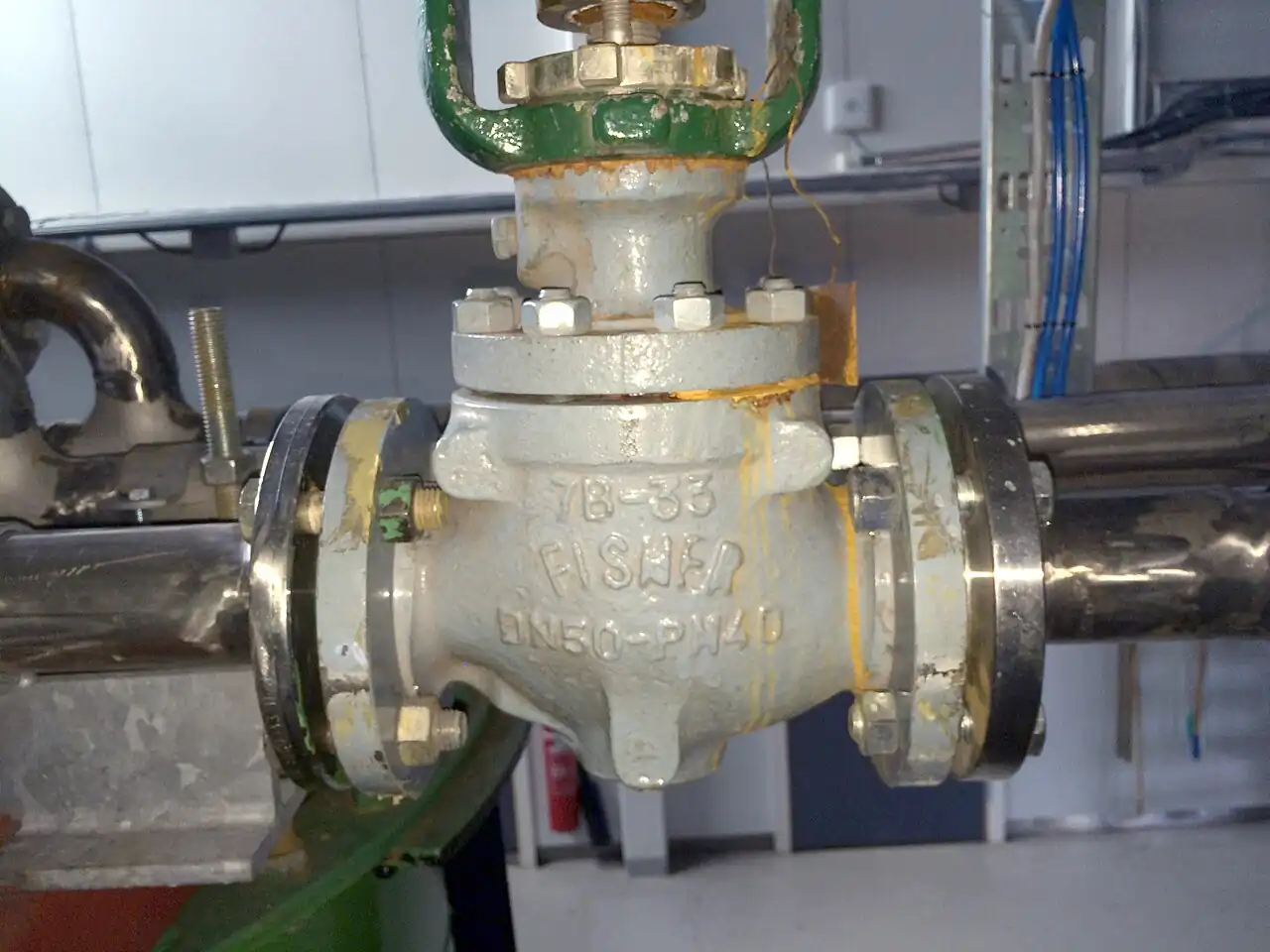
A pressure independent control valve, almost always shortened to PICV on drawings and sometimes written PIBCV to make the balancing function explicit, is a two-way hydronic valve that puts two machines in one body: an automatic differential pressure regulator ahead of a motorized throttling section, both in series on the coil branch. The regulator absorbs whatever pressure the system swings at the branch and holds the drop across the throttling section near constant, typically 15 to 25 kPa, while a calibrated setting scale on the stem limits maximum flow to the value the coil was designed for. Stem position then maps onto flow in a way the controls can trust at every load, which is the entire point of the product: terminal flow control that stays honest while pumps stage up and down.
Procurement engineers meet these valves at every hydronic terminal that matters: air handling unit coils, fan coil banks, radiators on variable flow loops, energy transfer stations built around a plate heat exchanger, and the coolant distribution unit and rack manifolds of data center liquid cooling. The decision this page settles is narrow and practical: whether the terminal deserves a true pressure independent valve, which size and setting range match the design flow, which minimum and maximum differential pressure window the branch will actually see, and which actuator closes against the available pump head. The answer lands as an RFQ line set, and every chapter below feeds that line set so the terminal is bought, not hoped for.
This page treats the pressure independent control valve as a purchasing object: what the internal delta P regulator changes in real numbers, how sizing and setting interact, which datasheet rows decide the purchase, and how the valve is commissioned and kept honest with test plugs. It is written for engineers who issue purchase specifications for hydronic systems, not for readers who want a brochure summary.
Chapter 1 / 06
What a Pressure Independent Control Valve Is and What Is Being Decided
Start with what the valve contains. Inside one body, in series on the branch, sit a differential pressure regulator and a motorized control plug. The regulator is a spring loaded diaphragm or piston assembly with its own seat: it opens only as far as needed to pass the demanded flow while dumping the excess branch pressure across itself, and in doing so it holds the pressure drop across the downstream control section at a near constant value, the 15 to 25 kPa band that most families use. The control section is a conventional plug and seat, actuated through a stem that carries a calibrated setting scale; the scale mechanically limits the maximum stroke, and therefore the maximum kv, to the flow the coil was designed for. One sentence captures the product: the regulator fixes the pressure side of the flow equation, the setting scale fixes the maximum, and the actuator positions the plug between zero and that maximum.
A caution belongs here because it misleads a specification meeting every year: the internal regulator is not a pressure reducing valve in the water supply sense. A pressure reducing valve holds a fixed downstream pressure against whatever flow arrives; the PICV regulator holds a fixed pressure difference across its own control section while flow changes by an order of magnitude. The two words sound adjacent and the two machines do different jobs, and the RFQ that confuses them buys the wrong product family twice.
What is actually being decided in this purchase is a set of commitments usually spread across three separate line items: the design flow the coil needs, expressed in m3/h and matched to a setting range; the differential pressure window the branch will see, minimum available at start-up and maximum at full pump staging; the close-off pressure the actuator must overcome to reach shutoff; and the actuation package, signal type and force class and fail behavior. A conventional purchase order covers a control valve and a balancing valve and a commissioning survey that reconciles them. The PICV purchase order covers one body that does both jobs, and the datasheet rows that replace the reconciliation are the rows in chapter 4.
The problem being solved is control authority, and it deserves numbers. Valve authority is the ratio of the pressure drop across the fully open valve to the pressure drop across the whole branch it serves. A conventional two-way control valve in a large system typically ends up with an installed authority of 0.25 to 0.5, because the design leaves most of the branch drop across pipes, coils, and fittings so the pump is not wasted at full load. At those authorities the installed flow characteristic of even a well made equal percentage plug distorts badly toward quick opening, and the loop gain the PID controller was tuned for at 50 percent load no longer exists at 20 percent. Worse, the distortion moves whenever anything else in the system changes: as other valves close, the branch drop rises, the authority falls further, and every terminal's calibration drifts together. The PICV attacks the cause rather than the symptom: because the regulator pins the control section drop at its 15 to 25 kPa regardless of branch pressure, the effective authority is 1.0 at all times, the installed characteristic equals the inherent one, and the calibration holds when the system around it changes.
Against its neighbors the boundaries are clean, and the full comparison lives in the selection chapter. A manual balancing valve sets a flow and has no internal regulator and no actuator: it is a fixed orifice with a handwheel, and it holds nothing when system pressures move. A conventional two-way control valve, in globe or characterized-ball executions, throttles with authority below 1 and historically needs the separate balancing valve plus a differential pressure controller across submains to approach what the PICV does in one body. A three-way valve belongs to constant flow legacy systems: it passes flow through the coil or around it, so the pump sees full flow at every load and part load pumping energy stays at design, which is exactly what variable flow plants pay to eliminate. A solenoid valve is two-position equipment, on or off within seconds, and cannot modulate a coil. A ball valve and a butterfly valve, in plain executions, are isolation hardware, and their characterized control versions still lack any pressure independence. Each of those products is the right purchase for its own duty; none of them is a pressure independent control valve.
The valve earns its keep at the system level as much as the terminal. In a plant served by a chiller and a cooling tower on the condenser side, the chilled water distribution is where PICVs concentrate, and the plant story is simple: total flow equals the sum of the terminal set flows, so pump speed can follow load down to the minimum stable flow of the plant. The controls chain is standard: a room or supply temperature transmitter feeds the loop, a PID controller or the building management system computes the demand, and the actuator positions the plug; at the plant, a differential pressure transmitter across the most remote branch trims the variable speed drive so the hardest terminal always has its minimum DP. A flow meter in the main confirms distribution for commissioning and energy accounting. In data centers the same valve appears in the coolant distribution unit and at rack manifolds, where a missed flow setting is a thermal event rather than a comfort complaint, and the argument for pressure independence is at its strongest.
Chapter 2 / 06
How the Internal Delta P Regulator Delivers Full Authority
Follow a unit of water through the valve. It enters the regulator section first, where a spring loaded diaphragm or piston holds a seat toward open or closed against the pressures on either side of the control section. When branch pressure rises, the imbalance pushes the regulator toward its seat and takes more of the drop across the regulator itself; when branch pressure falls toward the control section's set band, the spring opens the regulator further and takes less. The regulated quantity is the difference between regulator inlet and control section outlet, and the geometry is arranged so the control section always sees the same few tens of kilopascals. Above the control plug, the actuator positions the stem, and the setting sleeve under it stops the stem short of full stroke at the calibrated maximum. Nothing in this mechanism consumes power or needs wiring beyond the actuator: the regulator is a purely hydraulic device, and that is why the product survives three decades of pump staging without recalibration of its physics.
The flow equation explains why the arrangement matters. In words: flow through the control section equals its kv at the current stem position multiplied by the square root of the pressure drop across it. In a conventional control valve the drop is a moving target, changing with every other valve in the system, so stem position alone predicts nothing. In the PICV the drop is pinned at its 15 to 25 kPa band, so flow follows kv alone, and kv follows the stem. The square root of roughly 0.2 bar is a constant the maker has already absorbed into the scale graduations: the setting scale reads m3/h, and the actuator travels between zero and the set maximum on a curve that the manufacturer publishes as flow versus signal. When a commissioning engineer dials the sleeve to 0.45 m3/h on a DN 15 valve, that number means what it says as long as the branch supplies the minimum DP.
The minimum differential pressure is the number that makes or breaks an installation, and it deserves its own paragraph. Every family needs a start-up pressure to reach pressure independence: typically 30 to 35 kPa on the small sizes, where springs and seats are light, falling to 20 to 25 kPa on DN 100 and larger. Below that pressure the regulator sits wide open, the valve degenerates into a conventional throttling valve, and flows run below set values; the symptom is every terminal on the remotest index branch reading low on the same afternoon the plant runs one pump instead of two. The maximum differential pressure matters from the other side: the regulator must absorb the difference between branch pressure and the 15 to 25 kPa control band, and the body plus the actuator must hold shutoff against the highest branch pressure the plant can stage, which is why close-off is quoted up to the PN class of the body, 16 bar at PN16 and 25 or 40 bar on the heavier flanged versions. An actuator chosen without checking close-off against the pump's shutoff head produces the classic service call: the signal says closed, the indicator says closed, and the coil still heats, because the plug is parked a fraction off its seat by force it cannot overcome.
The characteristic follows from the same physics. The control plugs used in these valves are equal percentage family trims, chosen because that inherent shape combined with the coil's own flow to heat transfer curve yields a usefully linear installed response; with the drop held constant, the linearization the equal percentage law assumes actually holds. The result the loop sees is a gain that stays put: 10 percent signal change at 30 percent load produces about the same percentage flow change it produces at 70 percent, and the PID controller tuned in autumn does not need retuning in spring. Contrast that with the conventional control valve at authority 0.3, whose installed gain near closed can be several times its mid travel gain, and the commissioning hours saved stop being a marketing claim and become arithmetic.
Actuation is the second half of the mechanism and the half the RFQ must spell out. Three families cover the market. Thermal and electrothermal actuators use a heated wax or PTC element driving the stem over tens of seconds to a few minutes: they are quiet, inexpensive, and fine for slow temperature loops on fan coils and radiators, and the two-position versions share hardware with on-off zoning duty, though true modulation duty belongs to the modulating versions and not to a solenoid valve pressed into service. Electronic actuators use a gear driven motor with position feedback, accept 0 to 10 V, 4 to 20 mA, or digital MP bus signals, stroke in tens of seconds, and hold position on signal failure or spring to a fail position on power failure, depending on the ordered variant. The electric actuator force class must be matched to size and close-off: force demands rise from the small threaded bodies to DN 250, and the actuator catalog line states the maximum close-off pressure at which each force class still seats the plug. On flanged DN 150 to 250 duty, ordering the actuator and body as a factory matched set is standard practice, because the alternative is discovering the mismatch at first shutoff.
Two fluid effects close the mechanism chapter. Glycol: mixtures raise viscosity and lower density relative to water, and at 30 to 50 percent glycol the set flow reads several percent high unless the correction table in the datasheet is applied; most makers publish correction factors by glycol fraction and temperature, and the commissioning sheet should record which was used. Cavitation: when a branch carries a very high differential pressure across a small valve, the regulator seat can approach local flashing conditions exactly as any control valve would, and the datasheet cavitation or maximum DP per size line is the guard; the usual remedy is distributing the drop across two valves in series or choosing the larger body at a lower setting.
Chapter 3 / 06
Types, Construction, and Duty Boundaries
The compact threaded family is the volume product. DN 15 to DN 50 bodies in dezincification resistant brass or stainless steel, PN16 class, with female thread, press, or sweat ends, carry the regulator and plug in a single casting short enough to hang on a fan coil branch; a setting cap or hex adjusts the maximum flow, two pressure test plugs sit either side of the control section for a manometer, and the actuator mounts on a standard interface so thermal, electrothermal, and electronic heads interchange across the range. The Danfoss AB-QM 4.0 family in DN 15 to 50 is the reference execution of this architecture, and its datasheet layout, flow setting range per DN, minimum DP per size, close-off by actuator, is the format competing quotations should be made to answer. On fan coil and small air handling coils this is the honest purchase, and nothing larger is justified.
The flanged family carries the same architecture up the size range. DN 65 to DN 250 bodies in cast iron or cast steel, PN16, PN25, or PN40 by version, serve the big air handling coils, primary interfaces of major plant rooms, and the distribution headers where design flows climb from a few m3/h into the 240 m3/h class at the top of the range. On these sizes the setting mechanism is usually a threaded spindle with a graduated dial and a locking screw, the test plugs are supplemented by a drain or vent, and the actuators are the high force electronic types with spring return options. Face to face follows the maker's dimensional sheets rather than a single international standard, so the RFQ should demand the dimension drawing when the valve replaces hardware in an existing spool.
Electronic and instrumented versions extend the same body with data. The premium families add internal measurement, either a computed flow from position and differential pressure sensors or a true flow sensor, and report set flow, actual flow, and energy on the bus; the MP bus protocol lets one controller daisy chain dozens of valves; and detent or absolute positioning actuators make the stem position repeatable enough for the flow computation to stay in calibration. These versions earn their premium in monitored estates, district energy transfer stations, and data center halls, where the value is the telemetry itself: a terminal that reports its own flow closes the loop between design intent and operating fact without a commissioning visit.
Duty boundaries keep the family honest. The PICV is a water and water glycol machine: clean closed hydronic loops, up to about 50 percent glycol, 2 to 150 deg C by version, and not steam, not compressed air, not slurry bearing process liquor. It is not a safety device and never substitutes for a safety relief valve anywhere. It does not remove the need for isolation hardware: a butterfly valve or gate valve at branch entry and a ball valve at strainer bypass remain ordinary good practice, and a Y strainer upstream of small sizes on new systems catches the welding beads and sealant that otherwise engrave a soft seat in its first season. And when a terminal genuinely runs two-position, switching full flow on occupancy and off again, a zone valve at a third of the price is the honest purchase; the PICV premium pays for modulation under pressure independence, and a duty that never modulates never collects the dividend.
The table below compresses the families into the form a specification meeting argues from; values are the common spans of the established families and must be confirmed against the model datasheet before order.
Family
Construction and sizes
Flow setting class
Duty it wins
Compact threaded PN16
DN 15 to 50, brass or stainless, thread, press, or sweat ends, setting cap, test plugs
0.03 to 6 m3/h class
Fan coils, small AHU coils, radiator branches
Flanged PN16/25/40
DN 65 to 250, cast iron or steel, flanged, graduated dial setting
Zone valve or characterized ball valve, not a PICV
Full flow or zero
Occupancy switching duty that never modulates
Chapter 4 / 06
Key Specification Parameters
The datasheet rows below decide whether a quoted valve matches the branch; values are stated as the common spans of the established families and must be confirmed against the model datasheet before order.
Attribute
Typical range or options
What it decides
Nominal size
DN 15 to DN 250
Branch pipe matching and the flow setting range available
Pressure class
PN16 threaded; PN16, PN25, PN40 flanged
Body rating and the close-off ceiling the actuator works against
Flow setting range
About 0.03 to 240 m3/h family across sizes
Whether the coil design flow sits inside the dial with margin
Minimum operating DP
20 to 35 kPa by size
Pump head the branch must always supply for pressure independence
Maximum DP and close-off
Quoted per size and actuator, up to the PN level
Regulator absorption and shutoff under worst pump staging
Leakage class
EN 12266 rate A soft seat family; metal seat versions lower
Shutoff credibility and the test basis on the certificate
Medium and glycol
Water or water/glycol to about 50 percent
Freeze strategy and the flow correction factor in use
Temperature range
2 to 150 deg C family by version
Chilled, condenser, and low temperature hot water duty
Actuator signals
Thermal on-off, 0 to 10 V, 4 to 20 mA, MP bus
Loop integration, stroke speed, and fail behavior
Verification provisions
Two test plugs across the control section, position scale
Commissioning proof of set flow without extra hardware
The differential pressure window deserves the first paragraph because it is the row most often left unchecked. Two numbers frame it: the minimum DP the valve needs, 20 to 35 kPa by size, and the maximum branch DP the plant can generate at full staging, which the body must absorb and the actuator must close against. Between them sits the operating reality: the index branch at maximum simultaneous load with the smallest pump combination running must still see the minimum, and the branch nearest the pump at single pump shutoff must not exceed the maximum. A pump curve sketch with these two cases marked takes twenty minutes at design stage and settles what four commissioning weeks otherwise discover. When the window cannot be met, the remedies are structural: stage the pumps differently, add a differential pressure controller across the submain, or accept that the index branches need the next actuator force class.
The size table below gives the representative setting pattern across the range; treat it as the family shape and confirm the exact setting range, minimum DP, and close-off against the model datasheet, because families differ at the edges.
Setting range selection is a discipline, not a maximum chase. The design flow should sit in the upper half of the chosen range, ideally 60 to 90 percent of the dial maximum, so the plug works in its best characterized band and the spare setting is real rather than theoretical; a coil flow at the very bottom of a large range repeats the oversizing mistake the PICV exists to cure. The kv that corresponds to the set flow follows from the square root relation with the fixed drop, and makers publish it per graduation. Glycol correction applies to the setting, not the mechanism: at 40 percent glycol the same graduation passes less water equivalent flow than the dial says, and the correction factor, typically a few percent to around 10 percent by fraction and temperature, belongs on the commissioning sheet. Cavitation and sound close the check on high drop branches: where the branch DP runs toward several hundred kilopascals on small sizes, insist on the maker's cavitation limit per size and choose the larger body at lower setting rather than the tight small one working at its edge.
Chapter 5 / 06
Selection Decision Factors and RFQ Language
The selection sequence runs as a checklist, and each line eliminates a class of quotations before price comparison begins.
Fix the coil design flow in m3/h from the coil sheet, not from the pipe size: the flow chooses the valve, and the pipe only chooses the ends.
Pick the size whose setting range puts that flow at 60 to 90 percent of the dial maximum, using the size table pattern in chapter 4 as the first cut.
Compute the branch differential pressure window: minimum available at the index branch under smallest pump staging, maximum at the pump-near branch at shutoff, and check both against the datasheet minimum and close-off.
Confirm medium and temperature: water or water/glycol fraction to 50 percent, loop temperature inside the 2 to 150 deg C family band for the ordered version.
Choose actuation against the loop: signal standard, stroke speed, fail action on power failure, and force class proven against close-off at the maximum branch pressure.
State the verification provisions: two test plugs, graduated and lockable setting, position feedback where the estate audits terminal performance.
Keep the branch hardware honest: isolation valves, a Y strainer upstream on new systems, and unions so the valve can be serviced without cutting pipe.
Record the corrections in use: glycol fraction and factor, so the commissioning dial reading and the design flow reconcile on paper.
Against the neighboring hardware the PICV holds specific ground, and the comparison belongs here in the selection chapter rather than in a page title. The manual balancing valve remains the cheapest way to fix a flow and the wrong way to control one: it has no actuator, no signal, and no defense against system pressure changes, and where a terminal genuinely never modulates it is still the honest purchase. The conventional two-way control valve plus balancing valve plus submain differential pressure controller was the standard variable flow recipe for decades, and it still wins where a large process duty demands a heavy globe control valve trim with anti cavitation cages that PICV families do not offer; the globe control valve in its process executions absorbs pressure drops and fluid aggression that building services valves never see. The three-way valve survives in constant flow plants, benchwork, and coils that must always circulate to prevent freezing or stagnation, and its pumping energy penalty is the price of those requirements. The pressure independent control valve wins the ordinary building terminal: one body, one purchase order, one setting, full authority at every load, and immunity to the commissioning drift that the conventional recipe spends its life chasing. Choose the arrangement the loop and the plant actually need, and let the quotation prove which one it is selling. The plant context decides nothing about the terminal valve and everything about the pump: whether chilled water comes from a chiller bank or from the secondary side of a plate heat exchanger in a district transfer station, and whether condenser heat leaves through a cooling tower or a dry coil, the branch physics the PICV sees are identical, and that indifference to plant topology is half of what the product sells.
The application map below compresses the practice into the form a project file carries.
Application
Construction to specify
Check before order
Fan coil units, DN 15 to 25 branches
Compact threaded PN16, thermal or electronic actuator, setting cap
Minimum DP at index FCU with one pump running
AHU chilled and heating coils
Threaded to DN 50, flanged above; electronic actuator, 0 to 10 V or bus
Close-off against pump shutoff head; glycol factor if protected loop
Radiator zones on variable flow
Small PICV with zone control head, low minimum DP class
Setting range against per-radiator design flow
District energy transfer station
Flanged PN25/40, instrumented electronic version, MP bus
Maximum DP and close-off at full station differential
Data center CDU and rack manifolds
Instrumented versions with flow reporting, redundant actuation option
Setting evidence and telemetry for the thermal compliance file
Two-position occupancy switching
Zone valve instead; not a PICV duty
Do not spend the PICV premium where nothing modulates
The RFQ block should be written once and reused: quantity; size DN and end detail; PN class; design flow in m3/h with the chosen setting range stated; medium with glycol fraction and loop temperature; minimum available DP and maximum branch DP at the point of installation; required close-off; leakage class and test basis per EN 12266; actuator family, signal standard, fail action, and force class with its close-off proof; verification provisions, test plugs and graduated lockable setting; materials of body, plug, seat, and seals; corrections declared, glycol factor and basis; and the documentation set, datasheet, dimension drawing, setting table per size, and the commissioning method statement. A quotation returned without the minimum DP per size or the close-off by actuator is incomplete at any price, because those two numbers are the difference between a pressure independent control valve and an expensive conventional one with a dial on it.
Chapter 6 / 06
Installation, Standards, Failure Modes, and Maintenance
Installation is mostly about serviceability. Mount the valve with the actuator accessible and the setting scale readable, which on compact sizes usually means the stem axis horizontal or upright; most families tolerate any orientation up to DN 50 and restrict vertical pipe installations above that, and the maker's orientation line settles it. Give the branch its ordinary hardware: an isolation ball valve or butterfly valve at entry, a Y strainer upstream on new or dirty systems, unions where the pipe must come apart, and space to clip a manometer onto the test plugs. Five diameters of straight pipe are not hydraulically critical the way they are for a flow meter, but the test plugs read the control section differential, and a reading taken through disturbed flow or a half closed isolation valve proves nothing, so keep the immediate neighborhood clean and fully open when verifying.
Commissioning with a PICV is short when it is honest. Set the dial or cap to the coil design flow, correct for glycol if the loop carries it, and verify: a manometer across the test plugs should show the control section differential inside its 15 to 25 kPa band with flow present, and an ultrasonic or magnetic flow meter on the branch, or the valve's own reported flow on instrumented versions, should agree with the dial within the maker's tolerance. Record three numbers per terminal: set flow, measured flow, and available DP at the time. Then let the plant do its worst case: drop to the smallest pump combination and confirm the index branch still sees its minimum DP; a check valve or staging logic error at the plant shows up here as the whole remote wing reading low together. Trend the differential pressure transmitter at the plant and the supply temperature transmitter on the index coil through the same test: the DP trace proves the plant held its end, and the temperature trace proves the coil used the flow it was given. The controls desk tunes the loop with the actuator in service: the PID controller gains that worked on the old conventional valve at authority 0.3 are usually too timid on a full authority valve, and a retune collects the stability the hardware just paid for.
The standards frame is short and worth citing by name in the RFQ. EN 12266 covers industrial valve testing and defines the leakage rates and pressure test acceptance the seat certificate quotes, with rate A the bubble tight soft seat class the building services families claim. VDI 3805 structures the product data exchange for building services valves, which sounds administrative until a BIM deliverable is required and the maker who never published VDI 3805 data cannot be modeled. PED applies to the pressure retaining parts in the European market at the relevant category, and the actuator electrical families carry their low voltage and, on older thermal types, appliance standards.
Failure modes in service follow a short and predictable list. Seat fouling: debris past a damaged strainer lodges in the soft seat, leakage at closed signal appears first at high DP, and the fix is a seat service plus a strainer repair, not a valve replacement. Actuator under-sizing on close-off: the valve parks off seat at full pump staging and the overflows heat or cool an uncommanded space; the fix is the correct force class, discovered at design stage if the close-off line was checked. Setting scale drift: a dial nudged by a passing broom or a service technician changes terminal flow silently, which is why lockable settings and recorded commissioning values matter; the symptom is one space complaining while its neighbors behave. Regulator diaphragm fatigue: after years of pressure cycling the regulator loses its tight control band, flow starts rising with pump staging again, and the terminal slowly reverts to conventional behavior; a periodic check of the test plug differential at two pump stagings catches it in minutes. Glycol concentration drift: loops leak, get topped with water, and lose freeze margin while the flow correction silently changes; a refractometer check on the annual round keeps both honest. And the two-position misuse failure: a PICV ordered for an on-off duty strokes twice a day for twenty years without complaint, which is a purchase error rather than a valve failure.
Maintenance scales with duty. Clean water comfort duty earns an annual round: stroke test through the actuator, manometer reading at normal and staged down pumping, strainer inspection, dial lock verification, and a fluid check where glycol is involved. Data center and district energy duty adds quarterly telemetry review, comparing reported flows against commissioning values, and keeping one spare electric actuator per valve family on site, because the actuator is the wear item and the body is not. Every five years, a sample internal inspection on the hardest worked valves pays for itself in confidence. None of these checks costs a tenth of one recommissioning exercise, and each produces a number the next RFQ can use, which is how a purchasing file gets smarter instead of just older.
FAQ
What does pressure independence change in day to day operation?
The internal regulator holds the pressure drop across the control section at a near constant 15 to 25 kPa whatever the system does, so stem position maps directly onto flow at every load. When pumps stage up or down, other terminals open or close, or filters load, the branch pressure changes but the terminal flow does not. The practical results are stable loop gain for the controller, no flow redistribution between terminals as load moves, and commissioning values that stay valid for years.
What minimum differential pressure must the branch provide?
Every family needs a start-up differential pressure to reach pressure independence, typically 30 to 35 kPa on the small threaded sizes and 20 to 25 kPa from DN 100 upward. Below it the regulator sits wide open and the valve behaves like a conventional throttling valve, with flows below set values. The index branch under the smallest pump combination is the case to check at design stage, and the symptom of getting it wrong is a whole remote wing reading low together.
Can the flow setting be changed after commissioning?
Yes, that is what the setting scale is for. The dial or cap limits the maximum stem stroke, and therefore the maximum kv and flow, without changing the actuator or the signal range. If a coil is rebalanced or replaced, the setting moves to the new design flow provided it stays inside the size's setting range; a flow beyond the range means the size was wrong, not the setting. Verify any change with the test plugs and a manometer or flow meter, and record the new value.
Which control signals do PICV actuators accept?
Three families cover the market. Thermal and electrothermal heads are quiet, slow, and inexpensive, suited to fan coils and radiators. Electronic actuators accept 0 to 10 V, 4 to 20 mA, or digital MP bus signals, stroke in tens of seconds, and offer spring return fail positions. The choice follows the loop: fast or audited loops take electronic actuation, and the force class must be proven against the close-off pressure the branch can generate at full pump staging.
Does a PICV work with glycol and higher loop temperatures?
The building services families are rated for water and water/glycol mixtures to about 50 percent glycol and loop temperatures in the 2 to 150 deg C band by version. Two corrections apply: the flow setting needs the maker's glycol correction factor, typically a few percent at moderate fractions, and the freeze protection should be verified with a refractometer rather than assumed from the specification. Confirm the ordered version's exact temperature and glycol limits on the datasheet before committing.
Do I still need balancing valves and a commissioning survey?
Not at the terminal. The PICV replaces the terminal balancing valve and the proportional balancing pass, because the flow is set on the dial and held by the regulator. What remains is system work: the plant minimum flow, the differential pressure control across the distribution, and the index branch verification. An honest commissioning still records set flow, measured flow, and available DP per terminal; it just takes minutes per valve instead of the afternoon a balancing survey needs.
Why will my PICV not close against the pump?
The usual cause is close-off exceeded: the actuator's force class seats the plug only up to a stated differential pressure, and at full pump staging the branch exceeds it, leaving the plug parked a fraction open with heat or cooling leaking through. Check the pump shutoff head at the branch, not the nominal running head, against the actuator's close-off line, and order the next force class or a factory matched body and actuator set. A damaged seat seating on debris produces the same symptom and a different fix.