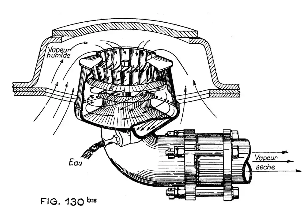
A reboiler is the heat exchanger that vaporizes part of the bottoms stream of a distillation column, an evaporator, or a stripper, and returns that vapor to the tower to supply the vapor traffic every separation stage needs. Heating comes from steam, hot oil, a hot process stream, or electric elements, and the working designs divide into kettle reboilers built on a TEMA K shell with an internal vapor disengagement space, vertical and horizontal thermosyphon reboilers that circulate liquid by natural convection through a shell and tube heat exchanger, and forced circulation reboilers that pump the liquid through with a circulation rate the designer sets directly. Duties run from a few hundred kilowatts on solvent recovery columns to over one hundred megawatts on crude towers, and the type choice fixes the column control scheme, the plot height, and the fouling story for the life of the unit.
Procurement engineers meet these units on chemical and petrochemical columns, gas plant stills, solvent recovery and ethanol trains, air separation reboilers, and refinery towers from naphtha splitters to vacuum columns. The decision this page settles is narrow and practical: which reboiler type matches the bottoms chemistry and fouling tendency, which heating medium and pressure the duty deserves, what circulation ratio and vapor fraction the process engineer assumed, and how TEMA shell choice and tube specification turn into a purchase order. The answer lands as an RFQ line set, duty and area and circulation and materials and TEMA type, and every chapter below feeds that line set so the exchanger is bought against the column it must serve rather than against a generic heat exchanger catalog page.
This page treats the reboiler as a purchasing object: how boiling regimes and critical heat flux cap what any type can do, how kettle, thermosyphon, and forced circulation designs divide the duty between them, which specification rows decide area and life, and how the whole decision folds into a defensible RFQ with a TEMA and ASME design basis. It is written for engineers who issue purchase specifications for column service, not for readers who want a brochure summary.
Chapter 1 / 06
What a Reboiler Is and What Is Being Decided
The defining act of the machine is vaporization at the bottom of a column. Everything upstream of a distillation tower prepares streams; the tower separates them on vapor liquid contact; and the reboiler is the engine that keeps vapor flowing up the trays or packing. Because the vapor rate it generates sets the internal reflux and the separation itself, the reboiler is a process element, not a utility exchanger, and its thermal design and its hydraulic coupling to the column are bought together. A shell and tube heat exchanger in feed service that fouls can be bypassed and cleaned while the plant degrades gracefully; a reboiler that fouls takes the column down with it, which is why type selection and fouling dominate every paragraph that follows.
What is being decided in this purchase is four commitments at once. First a type: kettle, thermosyphon, or forced circulation, because that choice sets the circulation ratio, the residence time of the boiling liquid, and the plot arrangement around the column skirt. Second a duty and an area with a stated overall heat transfer coefficient, in the practical band of roughly 500 to 2,500 watts per square meter kelvin depending on type and service. Third a heating medium and its conditions, since steam pressure, hot oil temperature, or process stream temperature fixes the driving force and the tube wall metallurgy. Fourth a mechanical basis, TEMA shell and tube arrangement, ASME Section VIII design pressure and temperature, tube material and pitch, and fouling allowance. A buyer who lets any of those four be filled in later by the vendor has bought a drawing, not a machine.
Against its neighbors the reboiler occupies deliberate ground, and the full comparison belongs in the selection chapter. The general shell and tube heat exchanger page covers the TEMA family as a class; this page covers the column reboiler duty specifically, where boiling on one side and level control on the other change the design rules. A falling film evaporator spreads liquid as a film to make concentration, not column vapor traffic, its own authority leaf. A flash tank is a vessel where pressure drop makes vapor with no heat input at all. A plate heat exchanger or spiral heat exchanger can serve as compact thermosyphon surfaces in clean low pressure duties, and gasketed plate units in particular appear as reboilers on small solvent columns, but pressure and temperature limits on elastomer gaskets cap that territory. Stating which neighbor the project is NOT buying is as useful in the RFQ as stating what it is.
Standards organize the datasheet. TEMA, the Tubular Exchanger Manufacturers Association standard, names the shell types and construction classes that every quotation will speak in: the K shell for kettle service, E and J and X shells for thermosyphon and kettle variants, and the tube side and rear head nomenclature that fixes how the bundle is maintained. ASME Section VIII Division 1 governs the pressure design, and API 660 adds purchasing rigor for petroleum service with its datasheet and inspection expectations. Heat transfer practice follows the classic boiling curve and its modern refinements, and vibration screening follows TEMA and HTRI style flow induced vibration checks, because a reboiler is one of the most vibration exposed exchangers in a plant. A datasheet that quotes none of these is a price tag, not a specification.
The station around the reboiler deserves naming in the RFQ too. Steam heated units need a steam trap or a condensate pot and a condensate return pump to keep the shell drained, a desuperheater where steam arrives superheated enough to matter, and a control valve on the steam or condensate side as the column heat input handle. Vacuum columns add a steam ejector or vacuum pump system and lower the boiling temperatures but tighten the thermosyphon hydraulics. Instrumentation reads the process: a level transmitter on the column boot or kettle, temperature transmitters on heating medium and vapor lines, pressure transmitters across the exchanger, and a safety relief valve protecting the closed sides. A sight glass on a kettle vapor space or level connection is cheap evidence at commissioning. Buying the exchanger without its station is how commissioning arguments start.
Chapter 2 / 06
How Boiling Behavior Sizes the Surface
Boiling regime is the physics that caps the duty. At low wall superheat, convective boiling transfers heat quietly into subcooled or saturated liquid and coefficients are modest. As the driving force rises, nucleate boiling takes over: bubbles nucleate at tube surface sites, agitation climbs, and heat transfer coefficients jump into the range that makes reboilers compact, often 1,000 to 3,500 watts per square meter kelvin for water like services in the nucleate band. Push the wall temperature higher still and the critical heat flux is reached, where vapor blankets the surface faster than liquid rewets it, coefficients collapse, and the tube wall temperature runs away. Design practice holds nucleate boiling comfortably below that ceiling, commonly at 70 to 80 percent of critical heat flux, because a reboiler operated past its boiling ceiling does not just lose capacity, it cokes, films, and fails.
Critical heat flux numbers give the buyer a sanity check on any quoted area. Classic correlations bracket the ceiling near 300 to 400 kilowatts per square meter for pool boiling of water like fluids at atmospheric pressure, falling with reduced pressure, viscosity, and surface tension, and falling further in vacuum service. If a quotation shows an implied average heat flux far above those bands for the stated conditions, either the vendor knows something exotic about the surface or the design leans on an enhanced tube whose performance claims the RFQ should demand test data for. If the implied flux is far below, the exchanger is oversized and the buyer is paying for metal, which is the cheaper error but still an error worth catching at paper stage.
Circulation ratio is the second sizing number the buyer controls. In a thermosyphon, the density difference between the liquid in the column draw and the two phase mixture returning through the exchanger drives flow, and the circulation ratio, kilograms of liquid circulated per kilogram of vapor generated, typically lands between 3 and 15 depending on service. The vapor fraction at the exchanger outlet, the inverse of that ratio, is commonly held below about 20 to 30 percent for clean hydrocarbons and much lower for fouling or vacuum service, because high vapor fractions dry the tube wall and move the surface toward the boiling ceiling. Forced circulation designs push the ratio higher still, 20 and up, specifically to keep wall wetting and velocity where fouling or viscosity would otherwise win. The RFQ should state the design circulation ratio and vapor fraction, because they fix piping size, elevation, and pump duty, not just thermal area.
Mean temperature difference behaves differently by type. A kettle boils at essentially one pressure and one composition, so its temperature profile is close to isothermal on the process side and the driving force is straightforward. A thermosyphon boils across a small temperature and composition range as the circulating liquid flashes partway to vapor, so the effective MTD sits slightly below the terminal value. Vacuum service compresses driving force dramatically: with boiling spreads of a few kelvin under a steam ejector held vacuum, area grows quickly, and the design leans toward low pressure drop tube arrangements and sometimes falling film or once through layouts instead of recirculating ones. The heating medium side matters just as much: condensing steam holds nearly constant temperature, hot oil cools across a real range that steals driving force, and a superheated steam header can be brought down by a desuperheater or accepted with a small correction.
Hydraulics and elevation finish the physics. A vertical thermosyphon hangs below the column with its tubesheet at a design elevation that sets the static head feeding the tubes, typically with the liquid level at or near the upper tubesheet, and the return line sized for two phase flow at low pressure drop; every elbow and every meter of line steals the driving force that circulates the liquid. A kettle sits at grade beside the column with a gravity feed line and a vapor return with disengaging space. Forced circulation moves the geometry problem into a pump: the pump must handle the liquid at temperature with adequate NPSH, which is why the draw is flooded and the pump often a vertical can or low NPSH design, and the control engineer gets a positive handle on circulation that thermosyphons only give through level and differential manipulation. Those hydraulic facts are specification content, because they decide steel and plot, not just thermal paper.
Chapter 3 / 06
Reboiler Types, Construction, and Duty Boundaries
The kettle reboiler is a TEMA K shell: a large diameter shell with a tube bundle covering only part of the cross section, an overflow weir holding a liquid level over the bundle, and a vapor disengagement space above where droplets settle before vapor returns to the column. Liquid feeds from the column boot, circulates over the bundle by natural convection, and the concentrated bottoms pump out from behind the weir. Kettles are forgiving: residence time is long, circulation is gentle, the bundle can be pulled for cleaning with the shell staying full, and the vapor space does its own demisting with a simple baffle or mesh where needed. The costs of that comfort are a large shell diameter, high residence time that fouling and heat sensitive fluids punish, and a liquid inventory that reacts slowly to control moves, so kettles favor clean to moderate services, vacuum duties where a big disengaging space helps, and columns where the bottoms product tolerates heat.
The vertical thermosyphon is the workhorse of the chemical industry: a TEMA E or similar shell and tube heat exchanger mounted with tubes vertical, process boiling in the tubes, and condensing steam or hot medium on the shell side. Liquid draws from the column bottom, rises through the tubes as it boils, and the two phase mixture returns to the column boot or directly above the bottom tray. Circulation is driven purely by density difference, there is no pump and no large vapor shell, residence time is seconds instead of minutes, and heat transfer coefficients are high because the two phase flow scrubs the wall. The trade is sensitivity: the design depends on getting elevation, line sizing, and vapor fraction right, it does not tolerate wide composition swings gracefully, and very viscous or severely fouling fluids defeat the gentle driving force. Horizontal thermosyphons put the bundle horizontal with boiling on the shell side, which suits large areas, low pressure drop, and bundles that must be pulled without disturbing column piping; they trade the vertical form factor for a wider footprint and more complex shell side two phase prediction.
The forced circulation reboiler adds a pump and takes the flow rate out of the hands of gravity. Liquid circulates through the exchanger at a set velocity, often suppressed to subcooled or low vapor fraction boiling with the actual flashing taken in a downstream separator or the column itself, and the designer buys exactly the wall shear and wetting the fluid needs. This is the answer for fouling services where velocity is the cleaning mechanism, for viscous bottoms where thermosyphon head cannot push the liquid, for salt bearing and polymerizing streams, and for vacuum systems that need predictable hydraulics. The costs are a pump with its maintenance and NPSH problem, a hotter wall film if suppression is imperfect, and higher piping complexity. Between the pure types sit stab in kettle bundles that mount directly in the column boot for small duties, and once through reboilers that vaporize the entire draw in a single pass where composition control wants no recirculation at all.
Construction details carry the warranty. Tube materials run 304 and 316 stainless for clean chemical service, carbon steel for hydrocarbon and steam side duty with corrosion allowance, duplex and higher alloys for chloride or sour exposure, and titanium where sea water cooling analogies apply; enhanced boiling surfaces, sintered porous or finned tube coatings, cut the temperature driving force needed for nucleate boiling and earn their premium on vacuum and close approach duties, with the RFQ demanding the test basis behind their claims. Baffle and tube pitch choices trade pressure drop against vibration risk, and a flow induced vibration check at the design and maximum flows is a TEMA requirement the buyer should see in the design report, because reboilers see high shell side crossflow velocities and two phase densities that shake tubes. Tubesheets, channel heads, and gasketed versus welded construction follow TEMA classes, R for severe petroleum service, C for moderate, B for chemical process, and the class letter belongs in the RFQ.
Boundaries are worth stating bluntly. A reboiler is not a fired heater, and duties that need flue gas temperatures or protection from a process runaway go to the fired heater page instead. It is not a waste heat recovery steam generator, which raises steam from turbine exhaust rather than boiling column bottoms. It is not an electric immersion package for small duties unless the RFQ explicitly entertains electric heating elements as the hot side, which clean low duty solvent columns sometimes do. The type map below compresses the boundaries into one table a specifier can scan before writing the RFQ.
Type
Typical circulation ratio
Best duty
Avoid when
Kettle, TEMA K
Natural convection pool boiling, effectively high
Clean to moderate fouling, vacuum and close approach duties, columns tolerant of residence time
Heat sensitive or polymerizing bottoms punished by long hot residence
Vertical thermosyphon
3 to 15
Chemical and hydrocarbon columns with clean to light fouling, compact plot under the skirt
Severe fouling, high viscosity, or unstable wide composition swings
Horizontal thermosyphon
4 to 12
Large duties, low pressure drop, pull bundles without disturbing column piping
Tight plots where the wide footprint does not fit
Forced circulation
20 and above
Fouling, salty, viscous, and vacuum services needing set velocity
Clean cheap duties where a pump is pure added cost and risk
Once through
Full vaporization in one pass
Composition critical towers where no recirculation is tolerated
Column boot level control cannot be arranged to protect the pass
Stab in bundle
Pool boiling in column boot
Small columns, pilot and specialty service
Duties above a few hundred kilowatts or where bundle pull is hard
Chapter 4 / 06
Key Specification Parameters
The table below decodes the datasheet lines that decide whether a quoted reboiler matches the column. Each row is a purchase defining parameter; the paragraphs after the table explain what to demand and what a weak answer looks like.
Attribute
Typical range or options
What it decides
Thermal duty
0.2 to over 100 MW
Vapor traffic, area, and the whole cost envelope with the heating medium
Overall coefficient U
500 to 3,500 W/m2K by type and service
Implied area; sanity check against boiling regime and fouling
Design heat flux
Held under critical, commonly 70 to 80 percent
Margin to vapor blanketing, coking, and runaway wall temperature
Circulation ratio and outlet vapor fraction
3 to 15 thermosyphon; 20 plus forced; vapor fraction under about 30 percent
Wall wetting, piping size, elevation, pump duty where applicable
TEMA shell and class
K kettle; E, J, X thermosyphon; class R, C, or B
Construction rigor, maintenance access, and quotation comparability
Tube specification
OD, pitch, length, material, plain or enhanced surface
Area per bundle, cleanability, boiling enhancement claims and their test basis
Design pressure and temperature
Per ASME VIII with corrosion allowance
Code envelope, relief setting, and winter or upset margin
Heating medium
Steam pressure, hot oil range, process stream, electric
Driving force, control scheme, metallurgy, and utility economics
Fouling resistance
Stated per side with basis
Excess area bought, velocity chosen, and cleaning interval implied
Materials
CS, 304, 316, duplex, higher alloys by chemistry
Corrosion envelope and gasket philosophy
The coefficient and flux rows deserve a paragraph of their own because they are where quotations blur. Ask for the design report basis: nucleate and convective boiling contributions, the critical heat flux calculation, and the velocity on the boiling side at design circulation. An implied average flux above roughly 60 kilowatts per square meter on a plain surface hydrocarbon service, or an area that assumes enhanced tubing without test data, are both flags worth a written answer. The fouling row is the second flag: excess area bought as fouling resistance lowers velocity in a thermosyphon and can make the fouling it was meant to absorb, a classic self defeating specification, so the honest RFQ states expected fouling mechanism and asks the vendor to optimize velocity and area together rather than stacking arbitrary fouling factors on a quiet design.
The heating medium row is an economics decision as much as a thermal one, and the table below lays the common choices against each other so the RFQ can name one instead of inheriting whatever the plant header happens to be.
Heating medium
Typical conditions
Why chosen
Watch out for
Saturated steam
3 to 40 bar g common
High coefficient condensing, easy control, constant temperature
Pressure limits on high temperature duties; condensate system and steam trap scope
Superheated steam
Header with superheat
Available header, no extra system
Desuperheater or correction needed; dry wall desuperheating zone robs coefficient
Hot oil or thermal fluid
To about 350 deg C
High temperature without pressure, simple pump around
Fireside or heater capacity, fluid film temperature limits, oil degradation
Hot process stream
Recovery duty
Heat integration and energy cost avoidance
Coupled upsets, fouling on both sides, control interaction with the donor loop
Electric elements
Small duties
Clean, compact, no utility header needed
Element sheath temperature limits, only sensible for small columns
The mechanical rows close the specification. Design pressure should reflect the credible upset, a blocked steam valve on a cold column, a vacuum break, or a pump deadhead, not just operating pressure, and the safety relief valve scope on both sides belongs in the purchase. Tube length and count trade against plot and pressure drop; channel and shell nozzles should be sized for the two phase return with the velocity limits that keep the line quiet. Where the service is sour or chloride bearing, material selection moves to the front of the conversation, and a spiral heat exchanger or plate and block alternatives enter only where their pressure envelope fits. The quotation that quotes an area without the design report behind it is asking the buyer to underwrite a calculation the vendor has not shown.
Chapter 5 / 06
Selection Decision Factors and RFQ Language
The decision sequence is short enough to run as a checklist in a specification meeting, and each step eliminates a class of quotations before price comparisons begin.
Characterize the bottoms honestly: composition range, viscosity at temperature, fouling and polymerization tendency, salt or solids content, and foaming behavior, because those four properties decide type more than duty does.
Fix the process envelope: operating pressure including vacuum where a steam ejector system holds it, boiling range, duty at design and turndown, and the control pairing, steam valve, condensate drum, or hot medium bypass, that will manipulate heat input.
Choose the type row from the chapter 3 table, then challenge it once against plot and capital: elevation under a skirt for a vertical thermosyphon, footprint for a kettle or horizontal, pump and NPSH scope for forced circulation.
Set the thermal basis: design report with boiling regime and critical heat flux margin, circulation ratio and vapor fraction, velocity on the fouling side, fouling mechanism stated rather than a stacked factor.
Fix the mechanical basis: TEMA type and class, tube specification with enhancement claims and test data, materials by chemistry, ASME design conditions with upset margin, and vibration screening at maximum flow.
Define the station: condensate handling with steam trap or condensate pot and return pump, desuperheater if the header demands, level and temperature and pressure instrumentation, safety relief valve scope, and winterization.
Fix the verification evidence: performance test tolerance, surface area and coefficient guarantee basis, vibration and hydraulic calculations delivered with the drawings, and material certificates.
Against neighboring equipment, the comparison a specifier needs runs as follows, and it belongs here in the selection chapter rather than in the page title. The general shell and tube heat exchanger covers the TEMA family as a class and this page takes the column duty where boiling and level control rewrite the rules. The falling film evaporator is a concentration machine with its own film distribution hardware, not a column vapor engine. The flash tank makes vapor from pressure drop with no heat input and pairs with, rather than substitutes for, a reboiler. A plate heat exchanger or spiral heat exchanger can be the thermosyphon surface on clean, low pressure, temperature limited duties where gaskets and pressure envelopes fit. Where the duty needs flue gas or a fired source, the purchase is a fired heater, and where steam is the product rather than the input, it is a heat recovery steam generator. Name the neighbors in the RFQ so the vendor quotes the right machine against the right duty.
The application map below turns that comparison into a table the project file can carry, pairing common services with the construction that survives them and the check that belongs before order.
Application
Construction to specify
Check before order
Clean solvent recovery column, 1 to 5 MW
Vertical thermosyphon, 316L tubes, steam at 10 bar g
Elevation and return line two phase pressure drop; vapor fraction under 25 percent
Vacuum column, close approach
Kettle with enhanced surface or falling film layout
Critical heat flux margin at vacuum; disengaging space; ejector system coupling
Fouling hydrocarbon bottoms
Forced circulation with set velocity, pull out bundle
Velocity on process side; pump NPSH at run down temperature; cleaning interval
Wall temperature margin to salt fusion or polymer onset; materials
Large refinery tower above 30 MW
Horizontal thermosyphon or kettle, class R
Vibration screening at maximum flow; two phase nozzle sizing; spare strategy
Small specialty column
Stab in bundle or electric element kettle
Duty ceiling; bundle access; control resolution at turndown
The RFQ block should be written once and reused. A complete block reads: bottoms flow and composition range with the fouling mechanism stated; operating pressure and vacuum basis, design and normal; duty at design and turndown with the control pairing; heating medium with pressure or temperature and its upset range; type named with TEMA shell and class; design circulation ratio and outlet vapor fraction where thermosyphon, pump conditions where forced; tube specification including OD, pitch, length, material, plain or enhanced with test basis; overall coefficient and area with the design report delivered; fouling resistance per side with basis; ASME design pressure and temperature with the upset case named; materials of construction for shell, tubes, and wetted internals; nozzles sized for two phase service; instrumentation list including level transmitter, temperature transmitters, and pressure transmitters with the control valve scope; condensate handling with steam trap or pot and return pump; safety relief valve basis on both sides; winterization; and the test, calculation, and certificate deliverables. A quotation returned without the design report or the circulation basis is incomplete at any price.
Chapter 6 / 06
Installation, Standards, Failure Modes, and Maintenance
Installation quality decides whether the hydraulics the designer assumed exist in steel. A vertical thermosyphon must be set at the drawing elevation with the liquid level at the column boot arranged where the thermal design put it, because a boot level even a few hundred millimeters off changes the circulation the unit was sized on. Return lines go in with the bends the two phase design allowed and no improvised additions, slope and drainage respected, and supports that let the exchanger grow without loading nozzles. Kettles sit level so the weir actually holds a level, and the vapor line rises to the column without pockets that trap condensate. Steam side piping drains before startup through the steam trap or condensate pot arrangement, with a warmup bypass around control valves so the first heat does not hammer a closed trim into its seat.
Commissioning proves circulation and control, not just temperature. On a thermosyphon, watch the column boot level, the exchanger differential, and the return temperature together: circulation established shows as a stable two phase return and a responsive column, while a failed circulation shows as a hot wall and a quiet column, and the fix is level, valve position, or venting, never more steam. On a kettle, verify weir overflow and vapor space behavior at design boil, check the demister or baffle carryover with the sight glass or a temporary inspection where one exists, and confirm the bottoms pump under the hot low level case. Prove the safety side: the safety relief valve set and installed per code on both closed sides, the control valve failure action checked against the column upset philosophy, and interlocks on low boot level or high differential tested as built, not as drawn.
Failure modes in service follow a short and predictable list. Fouling and coke lay down on the boiling surface raise the wall temperature and cut duty, seen first as slow loss of vapor generation at constant steam valve opening; the remedy is velocity, whether by design circulation or by cleaning, and the cleaning interval bought at specification should be a number, not a hope. Flow induced vibration appears as noise and tube wall thinning at baffle holes, and a design screened at maximum flow should have predicted it, which is why the vibration check belongs in the deliverables. Thermosyphon instability shows as cycling circulation and column temperature swings, usually traceable to boot level tuning, excess vapor fraction after a composition change, or a return line restriction that grew during maintenance. Kettle level failure, a weir or level control fault that uncovers the bundle, moves the surface toward the boiling ceiling and can coke a bundle in hours. Steam side problems are the familiar condensate story: a failed steam trap or an undrained condensate pot floods the shell, cuts area, and hammers; a desuperheater out of adjustment leaves superheat robbing coefficient; and the condensate return pump cavities when the pot runs hot and low.
Maintenance intervals scale with the fouling mechanism more than with running hours. Clean services run multi year campaigns with the exchanger opened only at plant turnaround, and the inspection reads wall thickness, baffle hole wear, and tube condition against the baseline recorded at commissioning. Fouling services plan the cleaning into the schedule the RFQ sized for, keep spare gaskets and a tube plug kit on site, and treat the difference between design and delivered coefficient as a record worth keeping, because it is the calibration for the next purchase. Instrument calibration follows the control importance of the loop: the level transmitter that feeds the column base control, the temperature transmitters on heat input, and the pressure transmitters on the exchanger differential are process evidence, not decoration. Winterization on the condensate side and heat tracing where the bottoms can freeze or wax completes the list, and every shutdown produces numbers the next RFQ uses, which is how a purchasing file gets smarter instead of just older.
FAQ
When should I choose a kettle over a thermosyphon?
Choose a kettle for vacuum and close approach duties where a large disengaging space helps, for moderate fouling that a gentle long residence boil tolerates, and for plots where the exchanger belongs at grade. Choose a thermosyphon when the bottoms are clean to lightly fouling, residence time must be short for heat sensitive material, and the plot under the column skirt fits a vertical unit. Kettles buy forgiveness with shell diameter and inventory; thermosyphons buy compactness with hydraulic discipline.
What circulation ratio should a thermosyphon reboiler have?
Typical design lands between 3 and 15 kilograms of liquid circulated per kilogram of vapor, with outlet vapor fraction held under roughly 20 to 30 percent for clean hydrocarbon service and lower for fouling or vacuum duties. The number is a design choice with consequences for piping, elevation, and wall wetting, so state it in the RFQ and require the vendor design report to show it.
How do I keep a reboiler off its critical heat flux?
Hold design heat flux comfortably below the critical value, commonly at 70 to 80 percent of ceiling, by sizing area for it rather than by throttling later. In practice that means checking the quoted implied flux against the 300 to 400 kilowatts per square meter pool boiling band adjusted for pressure and fluid properties, keeping the boiling side velocity and wetting up, and staying alert after any composition change that raises the boiling ceiling risk.
Is hot oil ever better than steam as the heating medium?
Hot oil earns its place above roughly 200 to 250 deg C, where steam pressures become heavy and expensive, and on sites without adequate steam headers. Steam remains the default below that band because condensing coefficients are high, temperature is constant, and control is easy. The trade is the oil heater capacity and fluid film limits against the steam system pressure class, and the RFQ should price both with the utility numbers.
What fouling resistance should I specify?
State the fouling mechanism and let the vendor optimize velocity and area together, rather than stacking an arbitrary fouling factor on a quiet design. Excess area bought as fouling resistance lowers thermosyphon velocity and can create the fouling it was meant to absorb, a self defeating specification. For fouling services the honest answer is usually forced circulation with a set velocity and a planned cleaning interval, with the fouling factor as a secondary margin.
Why does my vertical thermosyphon cycle and surge?
Three usual causes. First, boot level tuning: circulation depends on the static head between column level and upper tubesheet, and a poorly tuned level loop starves or floods the tubes. Second, excess vapor fraction after a composition or vacuum change dries the tube wall and destabilizes the two phase return. Third, return line restrictions added during maintenance steal the driving force. Fix the level, the vapor fraction, or the line, in that order of likelihood.
What deliverables should the purchase contract require?
The thermal design report with boiling regime and critical heat flux margin and the circulation calculation, the mechanical calculation to ASME Section VIII with TEMA type and class stated, the flow induced vibration screening at maximum flow, tube material certificates, the performance test method and tolerance, and the instrumentation and safety relief valve scope for the station around the exchanger. A quotation without the design report is asking the buyer to underwrite a calculation the vendor has not shown.