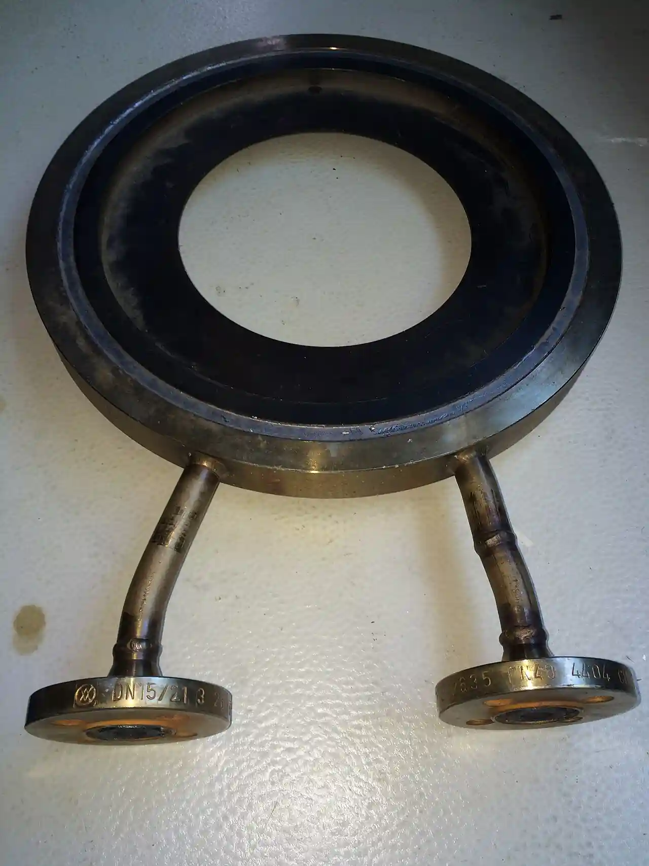
A restriction orifice, RO in process engineering shorthand, is a fixed bore or staged set of bores installed in a line to take a deliberate pressure drop or to cap a flow: a drilled plate in a holder, a bored spool, a multi-hole cage, or a stack of plates in series, chosen so that the passing flow is limited by geometry rather than by an operator or an actuator. Unlike a valve it has no moving parts and no trim to drift; unlike a metering run it is not built to measure anything. The device appears wherever a permanent, repeatable restriction is wanted: pump minimum-flow protection, blowdown and drain lines, letdown from high pressure headers, vent and flare lines, injection flow limiting, and deluge water control. Sizes span DN 15 to DN 600 bores from a fraction of a millimeter upward, with single-stage plates for moderate duty and multi-stage assemblies where one step would cavitate, flash, or deafen the plant.
Procurement engineers meet this device at the detail engineering stage, usually as a line on a piping specification with a calculated bore behind it. The decision this page settles is narrow and practical: whether the duty is honestly a fixed restriction, how much pressure drop must be taken and in how many stages, what the fluid does at the vena contracta, cavitation, flashing, or clean gas noise, and how the hardware, plate, holder, spool, or staged assembly, is specified so the delivered bore matches the process calculation. The answer lands as an RFQ line set: fluid and phase, pressures and temperatures, required flow cap, stage count, materials, and end connections. Every chapter below feeds that line set so the restriction is bought on hydraulics, not on a hole saw.
This page treats the restriction orifice as a purchasing object: what fixed-restriction duty is and is not, how single-stage, multi-hole, and multi-stage constructions divide the work, how cavitation, flashing, and noise set the staging, and how the calculation basis and hardware combine into a defensible RFQ. It is written for engineers who issue purchase specifications, not for readers who want a brochure summary.
Chapter 1 / 06
What a Restriction Orifice Is and What Is Being Decided
The restriction orifice earns its place by being deliberately crude. A valve throttles under command; a control loop moves a trim to hold a variable. The RO does neither: its bore is fixed at manufacture, its characteristic is a curve the hydraulicist computed once, and its adjustment is a shutdown and a swap. That permanence is the product. Wherever a line must never pass more than a defined flow no matter what an operator does, wherever a continuous small bleed must run unattended for years, wherever a steady letdown protects downstream low pressure equipment, the fixed bore is simpler, cheaper, and more tamper resistant than any active device, and it fails safe in the sense that its failure mode is erosion of a known geometry, not a stuck actuator.
What is actually being decided in this purchase is the credibility of a calculated hole. The buyer commits to a duty number, flow or pressure drop, a stage count, and a construction, and every one of those decisions follows from the fluid's behavior at the restriction. A single plate taking 40 bar of liquid drop does not produce a quiet 40 bar drop: it produces cavitation that eats the plate and the pipe within weeks. A gas letdown through a single small bore can produce a jet noise that violates the site's hearing program. The engineering decision is how to split and shape the drop so the energy dissipates without destroying hardware, and the purchase decision is to demand the calculation behind the delivered bore, because a hole drilled without the hydraulic basis is a guess in metal.
The family context matters because the piping world already owns several bored and throttling devices, and the RO must not be confused with any of them. An orifice-plate-flowmeter is a measurement instrument: a plate with defined geometry and pressure taps, installed in a meter run with straight lengths, calibrated by the ISO 5167 family so the measured differential yields flow; its purpose is to measure, and its pressure drop is a regrettable cost. The orifice-flange is the hardware that holds a metering plate and carries its taps, again a measurement article. A needle-valve meters small flows under command with a variable needle; a globe valve offers occasional hand throttling where the process tolerates it; a globe-control-valve modulates continuously on a signal; a pressure-reducing-valve holds a downstream set point automatically. The restriction orifice shares the bore geometry with the first two and shares a throttling intent with the last three, but it neither measures nor modulates: it is a fixed hydraulic element, closer in spirit to a choke-valve in its fixed trim configuration than to any instrument, and the RFQ should keep the categories straight because the certifications, tolerances, and prices all differ.
Standards and calculation practice organize the datasheet. The hydraulic arithmetic leans on the same orifice flow mathematics that the ISO 5167 and ASME MFC families formalize for metering, applied at restriction conditions with the appropriate discharge coefficients, and manufacturers of dedicated RO hardware publish their own sizing practice built on that base. Hardware standards follow the piping: flanges per ASME B16.5 or EN 1092, with the orifice flange style used where taps are wanted, wall thickness per the piping code, and materials per the line class. Noise assessment for gas letdowns leans on the process industry noise practice embedded in piping design codes. A datasheet that quotes no calculation basis is a price tag, not a specification.
The RFQ should also name the neighbors the RO serves, because the device is usually part of a station. A deluge-valve trim often includes a small restriction orifice in its control loop to pace opening; a pump protection line pairs the RO with a check-valve and an isolating ball-valve so the minimum flow path cannot backflow; a flare header's purge runs through a bored spool sized to hold velocity above the flame-speed threshold, in company with a flame-arrester where the hazard analysis calls for one. Instrument connections around the RO, a pressure-gauge or pressure-transmitter tap upstream and downstream, and a differential pressure gauge where the drop itself is the process signal, complete the station, and the instrument manifold that serves the DP measurement belongs in the same purchase package when it exists.
Chapter 2 / 06
How the Bore Takes the Drop
The physics is the orifice equation wearing work clothes. Flow through a restriction scales with the bore area and the square root of the pressure drop, with a discharge coefficient correcting for the vena contracta, the jet contraction just downstream of the bore where the flow area is smallest and the static pressure lowest. For liquids, the calculation checks the pressure at that contraction against the vapor pressure: if it falls below, vapor forms and then collapses downstream as pressure recovers, which is cavitation, and if the downstream pressure itself sits below vapor pressure, the fluid stays vapor, which is flashing. Both conditions are process facts, not defects; the design question is whether they are accommodated by staging or accepted with hardened materials and short pipe runs to a receiver.
Choked flow is the gas side of the same coin. When the ratio of upstream to downstream pressure exceeds the critical ratio, roughly two to one for air and similar diatomic gases, the jet through the bore reaches sonic velocity and the mass flow stops responding to downstream pressure: the RO caps the flow at a value fixed by upstream conditions and bore area. Most gas restriction duties live deliberately in this regime, because the cap is what the safety case wants, vent lines, relief headers, and purge flows that must hold a defined maximum no matter what the back pressure does. The calculation then uses the compressible flow mathematics with the correct critical conditions, and the delivered bore tolerance matters directly: a bore a few percent oversize passes a few percent more flow, and in a relief-adjacent duty that margin belongs to the study, not to the machine shop.
Permanent pressure loss is the honest cost figure. A metering orifice recovers some of the contraction loss in the downstream cone, and the ISO data quantifies exactly how much; a sharp-edged restriction plate recovers little, so nearly the full drop is permanent, which is precisely what a letdown duty buys. The specifier should demand the permanent loss statement per stage, because multi-stage assemblies divide the total drop into steps that each sit below the damage threshold, and the step allocation is the engineering content of the product: pressure recovery through spacing between stages, eddies dissipating in the cavity between plates, and a velocity profile that re-forms before the next bore.
Two verification numbers decide whether the delivered hardware performs. The first is the bore itself: the calculation names a diameter, and the manufacturing tolerance on that diameter, with the edge condition sharp or quadrant as specified, is the difference between the studied flow cap and a shop floor approximation. The second is the acoustic and erosion statement: for gas, the predicted noise at the operator position with the silencing arrangement if needed; for cavitating liquid service, the accepted cavitation intensity and the material behind it. Both numbers appear in a competent offer, and both can be checked after installation with a differential pressure gauge across the device and a sound level meter at the pipe, which is an hour well spent at commissioning.
The flow-meter question closes the loop on identity. Engineers sometimes propose measuring across an RO with a DP transmitter and reading flow from the calibration curve, and the practice works where the geometry is documented and the coefficients are known; several plants run exactly this arrangement with a differential pressure transmitter on the taps. But that converts the RO into a crude metering run, with none of the ISO 5167 straight-length guarantees, and the honest engineering statement is that a venturi-tube or flow-nozzle exists when accuracy matters at high pressure recovery, while the RO exists when a fixed cap matters and the measurement, if any, is a byproduct. Keeping the purposes separate keeps both purchases honest.
Chapter 3 / 06
Single-Stage, Multi-Hole, and Multi-Stage Construction
Three construction families cover the catalog landscape. The single-stage plate is one drilled bore in a plate, held in a holder or clamped between flanges: cheapest, standard for moderate drops, clean liquids, and gas duties whose noise stays within limits. The multi-hole plate replaces one large bore with an array of smaller bores sharing the total area: the jets break up coherence, the acoustic signature drops, and the plate resists plugging better than one small hole of equal area, which is why purge and vent duties favor it. The multi-stage assembly stacks plates or bored spools in series, each stage taking a fraction of the drop: the standard answer for high pressure liquid letdown where cavitation must be suppressed, for flashing service, and for gas drops whose single-stage noise would be intolerable. Within each family the buyer still chooses holder style, materials, and end connections, and those choices carry more service weight than the family name.
Holder and body styles follow the piping. A plate can clamp between existing flanges, seated on the flange gasket face, which suits low pressure utility duty and makes the bore swap a flange drop; a dedicated holder, in the style of an orifice flange union, carries the plate with its own bolts and sometimes taps, and suits repeated changeouts; a bored spool welds or flanges into the line as a pipe piece, integral and erosion resistant, standard for severe service; and the multi-stage assembly ships as a welded cartridge or flanged body with internal stage plates and intermediate chambers. Material selection follows the fluid and the failure mode: stainless plates for clean hydrocarbon and utility service, hardened or coated trims for erosive and cavitating duty, and carbon steel bodies where the line class permits. The edge condition of each bore, sharp for classic coefficient behavior or rounded for erosion resistance, is a drawing line item that too many orders leave to the shop.
Sizing discipline differs by family. A single-stage plate lives within the drop that one vena contracta can survive: process practice keeps the stage pressure ratio and the cavitation index inside proven envelopes, and beyond them the answer is staging, not optimism. Multi-hole plates balance jet interaction and total area: holes spaced so the jets do not merge within the plate thickness, an area sum that reproduces the single-bore coefficient within tolerance, and a hole count that keeps each bore above the plugging size for the fluid's solids. Multi-stage assemblies allocate the total drop across stages, usually evenly or slightly front-loaded, with chamber lengths that let the jet dissipate before the next bore; the manufacturer's stage hydraulic design is the product, and the RFQ should demand the stage-by-stage pressure profile as a deliverable.
The duty map below consolidates the family choice into one table a specifier can scan before writing the RFQ; it pairs common services with the construction that survives them.
Service
Suitable construction
Construction to avoid
Gas vent or purge, flow cap, moderate drop
Single or multi-hole plate, stainless
Single small bore at high ratio without noise check
Pump minimum continuous flow protection
Bored spool or plate with check and isolation
Undersized bore welded without isolation for swap
High pressure liquid letdown, cavitation risk
Multi-stage assembly with hardened trims
Single plate taking the full drop in liquid
Flashing letdown to a receiver
Multi-stage with erosion-resistant body and short run
Long downstream piping in flashing vapor path
Blowdown or drain to atmosphere
Multi-hole plate sized for choked cap
Plate material unhardened where erosion is expected
Deluge or water spray flow pacing
Small plate or union-type holder in trim line
Bore without documented calculation basis
Boundaries are worth stating bluntly. This device is not a flowmeter, and buying it to measure is buying the wrong instrument at the wrong accuracy. It is not a regulator: a pressure reducing valve holds a set point under varying flows, while the RO holds nothing, it only resists. It is not a safety relief valve or a choke-valve trim replacement in multiphase oilfield wells service, though it borrows choke mathematics in gas caps. And it is not a substitute for a control loop where the process genuinely varies: if the flow cap must move with operating cases, the correct instrument is a globe-control-valve or a needle-valve, and the RO belongs only where the cap is constant by design. The selection chapter returns to these lines; the point here is that the fixed bore is a one-setting device in a multi-setting world.
Chapter 4 / 06
Key Specification Parameters
The table below decodes the datasheet lines that decide whether a quoted device matches the duty. Each row is a purchase defining parameter; the paragraphs after the table explain what to demand and what a weak answer looks like.
Attribute
Typical range or options
What it decides
Fluid and phase
Gas, clean or dirty liquid, flashing or cavitating service
Calculation regime and construction family
Inlet pressure and temperature
Full line conditions, design and operating
Choked flow cap, materials, stage count
Required drop or flow cap
Stated as permanent loss or maximum passing flow
The single hydraulic duty the bore is drilled to
Stage count
Single, multi-hole, or 2 to 10+ stage assemblies
Cavitation, flashing, and noise management
Bore and tolerance
Calculated diameter with manufacturing tolerance
Delivered flow cap versus studied value
Edge condition
Sharp or quadrant entry per specification
Discharge coefficient stability and erosion life
Materials
Stainless standard; hardened or coated trims for erosion
Service life in cavitating and dirty duty
Body and ends
Plate between flanges, holder, welded spool, flanged body
Installation, swap-out, pressure boundary
Noise statement
Predicted sound level and attenuation arrangement
Compliance with site hearing limits
Cavitation and flashing index
Stage ratio and cavitation number per stage
Whether staging is honest or cosmetic
Taps and instruments
Optional upstream and downstream taps for DP reading
Byproduct flow indication and monitoring
Calculation deliverable
Stage-by-stage profile and hydraulic basis
Auditability of the delivered bore
The bore tolerance row deserves its own paragraph because it is the row that silently changes the plant. The hydraulicist computes a diameter to two decimal places; the shop drills to a tolerance; the flow cap moves with the area, and area moves with diameter squared. An RO ordered without a stated tolerance and edge condition can arrive with a punched, burred bore whose effective area differs from the calculation by several percent, and in a purge or relief-adjacent duty that margin was never the buyer's to give away. The fix costs one line: order the bore with the tolerance and the edge geometry on the drawing, and ask for the as-drilled measurement as a delivered document.
The stage profile table is the second argument in every severe service meeting, and the compressed form below is the one a specification file can carry. It shows how the total drop divides and what each family is honestly for.
Construction
Drop per element
Where it earns its cost
Single-stage plate
One step, moderate ratio
Clean liquids and gas caps within noise limits
Multi-hole plate
One step, area shared by jets
Purges and vents needing quieter, plugging resistant bores
Multi-stage assembly
Total drop split across 2 to 10+ stages
High drop liquid letdown, cavitation and noise control
Bored spool
One integral machined restriction
Welded severe service and minimum flow lines
The instrument rows close the specification. Taps on either side, read by a differential pressure gauge or a differential pressure transmitter where the control system wants the signal, turn the fixed bore into a monitored element: the DP trend is the direct health indicator, rising DP at constant conditions means the bore is eroding open or plugging, and the alarm thresholds come straight from the hydraulic basis. A pressure transmitter upstream keeps the operating state visible where the cap depends on inlet conditions. The quotation that prices the plate and leaves the calculation and the taps as an exercise is not a complete quotation.
Chapter 5 / 06
Selection Decision Factors and RFQ Language
The decision sequence is short enough to run as a checklist in a specification meeting, and each step eliminates a class of quotations before price comparisons begin.
Confirm the duty is genuinely fixed: constant cap or continuous letdown, no operator adjustment in the operating envelope, or the duty belongs to a valve.
State the fluid honestly: phase, vapor pressure or gas ratio, solids loading, and the erosional velocity limits the line class carries.
Fix the hydraulic duty: required permanent drop or maximum passing flow, with inlet conditions and the downstream pressure basis.
Check the single-stage envelope: cavitation index for liquids, critical ratio for gases, and the noise prediction against site limits.
Stage where the envelope fails: allocate the drop across stages or hole arrays, and demand the stage-by-stage profile as a deliverable.
Choose hardware to the line: plate, holder, spool, or flanged multi-stage body, with end connections and pressure class matching the piping.
Fix materials and edge geometry: stainless standard, hardened or coated trims for cavitation and erosion, and the bore tolerance on the drawing.
Plan the station: isolation valve, check valve where backflow is credible, taps and DP reading, and the swap-out procedure at shutdown.
Fix the evidence package: hydraulic calculation sheet, as-drilled bore record, material certificates, and the noise statement for gas duty.
Against neighboring devices the comparison a specifier actually needs runs as follows, and it belongs in this selection chapter rather than in the page title. The orifice-plate-flowmeter with its orifice-flange hardware exists to measure flow within ISO tolerances and spends pressure drop to do it; the restriction orifice exists to spend pressure drop and measures nothing unless taps are added as a byproduct. A pressure reducing valve holds a downstream set point continuously; the RO holds no point, it caps a flow or splits a drop, and where the set point varies the valve is the honest answer. A needle-valve gives manual metering adjustability at small flows; a globe-control-valve modulates on a signal; the RO is the choice when the word fixed is literally the specification. Choose the device the process means, and let the hydraulic arithmetic, not the supplier's stock list, decide the bore.
The application map below turns that logic into a table the project file can carry.
Application
Construction to specify
Check before order
Pump minimum flow protection line
Bored spool or plate with check and ball isolation
Choked cap at relief case inlet conditions
High pressure water or condensate letdown
Multi-stage assembly, hardened stages
Stage cavitation indices and downstream velocity
Gas purge to flare or vent header
Multi-hole plate, choked regime
Noise at operator position and purge velocity
Blowdown to atmosphere
Multi-hole or staged plate, erosion allowance
Two-phase behavior and receiver design
Injection flow limiting
Single plate with DP taps and transmitter
Bore tolerance and as-drilled record
Deluge trim pacing
Small union-type restriction holder
Calculation basis filed with the system documents
The RFQ block should be written once and reused. A complete block reads: quantity; fluid with phase, vapor pressure or gas composition, and solids; design and operating pressures and temperatures at inlet and outlet; required maximum passing flow or required permanent pressure drop with the calculation case named; single-stage or staged preference with the stage allocation basis; bore diameter calculation basis with the standard or method cited; bore tolerance and edge geometry; materials of plate, holder or body, and any hardfacing; end connections, flange class or weld prep, and face-to-face; taps with size and location where monitoring is wanted; cavitation, flashing, and noise statements for the offered geometry; special requirements, erosional velocity check, drain or inspection connections, and code calculations to be submitted; and the documentation set, hydraulic sheet, as-drilled record, material certificates, and where applicable the stage profile. A quotation returned without the calculation sheet or the bore tolerance is incomplete at any price.
Chapter 6 / 06
Installation, Standards, Failure Modes, and Maintenance
Installation quality decides whether the studied hydraulics survive contact with the field. Install the plate or spool with the flow direction the calculation assumed, marked on the hardware by the manufacturer, because a backwards restriction still restricts but with a different, uncalculated coefficient. Give a single-stage gas jet the straight downstream run the noise statement assumed, and where the statement includes an expander or silencer, install it; the decibels live in that hardware. Flanged plates seat on their gasket faces square, and the flange bolts come up in pattern, because a cocked plate changes the jet and a leaking holder erodes the seat in months. Multi-stage bodies hang or mount to the piping stress design like any valve body, with supports that keep nozzle loads inside the line class.
Commissioning practice protects the basis. Record the as-installed DP at a known flow with a differential pressure gauge, and file it against the calculation: that single number is the baseline for every future health judgment. Walk the station, isolation, restriction, check where fitted, and confirm the swap-out procedure that a fixed bore eventually asks for. On gas duty, take the sound level meter to the operator position and compare against the statement in the offer. On liquid letdown, listen for the gravel sound of cavitation that staging was supposed to remove, and treat it as a warranty conversation, not an acoustic curiosity.
The standards set the verification frame. The orifice flow mathematics is formalized in the ISO 5167 and ASME MFC measurement standards, which the restriction calculation borrows with the appropriate coefficients; flange hardware follows ASME B16.5 or EN 1092 with the orifice flange style where taps are specified; piping codes govern wall thickness, erosional velocity, and supports; and site or national noise practice governs the acoustic acceptance. Material certificates follow EN 10204 as in the rest of the line class. A specification that cites these by name transfers the burden of proof to the supplier, which is where it belongs.
Failure modes in service follow a short and predictable list. Erosion of the bore: solids and cavitation open the diameter, the cap rises, and the DP at constant flow falls; the trend catches it a shutdown early, and the fix is a hardened plate or better staging. Plugging: a small single bore in dirty service silts, the cap falls, and the multi-hole answer belongs in the next order. Noise and vibration: a gas jet at high ratio excites the downstream piping, fatigue cracks follow the loudest octave, and the answers are staging, insulation and lagging per the acoustic design, or a proper silencer element. Gasket and seat erosion in flanged holders: a weeping holder is a jet cutting the flange face, and the repair is the gasket plus a look at the jet impingement. Corrosion: the plate thins, the coefficient drifts, and the material upgrade is cheaper than the unplanned shutdown.
Maintenance intervals scale with duty severity. A clean gas purge plate earns a DP reading at the operator round and an inspection at major shutdown; a cavitating letdown assembly earns scheduled DP trending, annual bore measurement where the calculation is safety-adjacent, and stage inspection at every turnaround; a blowdown device earns a post-every-use check because each blowdown is an erosion event. Every check produces a number, bore diameter, DP at known flow, sound level, and those numbers are the real condition monitor for the device. None of these checks costs a tenth of one eroded-open cap that let a pump run off its curve, and every one of them feeds the next RFQ with plant-specific evidence, which is how a purchasing file gets smarter instead of just older.
FAQ
How is a restriction orifice different from a metering orifice plate?
Purpose and hardware. A metering plate is part of a flowmeter: defined geometry, pressure taps, calibrated straight lengths, and ISO or ASME coefficient tables so the differential yields an accurate flow, with pressure drop as a cost. A restriction orifice is a hydraulic device: its bore is calculated to cap a flow or take a drop, it has no measurement obligation, and it is not built with the metering tolerances or straight-run guarantees. You can add taps and read approximate flow across an RO, but that is a byproduct, not a meter.
When do I need a multi-stage restriction orifice?
When a single stage cannot take the whole drop without damage: liquid service where the vena contracta would fall below vapor pressure and cavitate, flashing service, and gas letdowns whose single-jet noise would exceed site limits. Staging divides the total drop so each stage stays inside proven cavitation and acoustic envelopes, with chambers between stages letting the jet dissipate. The rule of thumb is not a pressure number but a stage index: run the cavitation check per stage and stage until every stage passes.
Why choose a multi-hole plate instead of one bore?
For acoustics and plugging resistance. Several small jets sharing the total area break up the coherent jet that makes single-bore noise, and each bore stays above the plugging size for the fluid's solids where one equivalent hole would be smaller. The area sum reproduces the restriction coefficient within tolerance. Multi-hole plates are standard on purge, vent, and blowdown duties for exactly those two reasons.
What is choked flow and why does it matter here?
When upstream to downstream pressure ratio exceeds the critical ratio, roughly two to one for air, the jet through the bore reaches sonic velocity and mass flow stops responding to downstream pressure. The cap then depends only on upstream conditions and bore area, which is exactly what a vent or purge safety case wants: a defined maximum regardless of back pressure. The calculation must use compressible choked flow mathematics, and the bore tolerance flows straight into the cap, which is why the as-drilled diameter belongs in the delivered documents.
Can I measure flow across the restriction orifice?
Approximately, if the geometry is documented. Install taps and read the differential with a differential pressure gauge or transmitter, then apply the coefficients from the calculation sheet to get a byproduct flow indication. Without the metering straight lengths and calibrated tolerances of a true flow run, treat the accuracy as indicative. Where the measurement matters to custody or control, buy the right instrument: an orifice meter run, a venturi-tube where recovery matters, or a flow-nozzle in high velocity steam service.
How tight should the bore tolerance be?
Flow scales with area and area with diameter squared, so a diameter tolerance of one percent moves the cap about two percent. State the tolerance on the drawing, require the edge geometry, sharp or quadrant, that the calculation assumed, and ask for the as-drilled measurement as a delivered record. In relief-adjacent or purge safety service the tolerance is part of the study margin, not a machine shop courtesy, and orders that leave it unstated have already given the margin away.
Why did my restriction orifice get louder over time?
Usually erosion. A bore that has opened or a plate edge that has rounded changes the jet, and often the cap has risen with it; the DP at constant flow is the check, and it will read lower than baseline if the bore has grown. Noise can also rise if a downstream silencer or expander element has corroded away internally. Take the sound level reading at the operator position, compare with the commissioning file, and inspect the bore at the next shutdown; the fix is a hardened or staged replacement, not thicker lagging on an eroding jet.