A servo valve is an electrically commanded hydraulic flow control valve built to close high bandwidth motion loops. A torque motor or a direct drive linear motor converts a small electrical command into a force, the force positions a precision ground spool inside a close tolerance sleeve, and the spool meters pressurized oil to a hydraulic actuator in proportion to that command. A feedback element closes the position loop inside the valve itself: a thin spring wire between spool and pilot stage in flapper designs, or an LVDT measured by the valve driver in direct drive designs. Rated flows run 4 to 100 L/min at 70 bar per metering land in the common frame sizes, with supply pressures from 70 to 315 bar, resolution better than 0.1 percent, and pilot stage natural frequencies in the 150 to 400 Hz class for flapper hardware.
Procurement engineers meet these valves on materials test rigs running fatigue programs, on flight simulator motion platforms, on steel mill automatic gauge control and runout table stands, on injection molding and die casting machines, on steam turbine governors, and on marine steering gear. The decision this page settles is narrow: whether the loop genuinely needs servo class bandwidth, which pilot architecture fits the fluid and the maintenance regime, what rated flow, command signal, feedback, and null leakage to specify, and above all what cleanliness class and filtration the purchase commits the plant to for the life of the valve. The answer lands as an RFQ line set: architecture, flow at 70 bar, supply pressure range, command and feedback, ISO 4406 cleanliness class with filtration, dither policy, connector, and the test evidence behind each number.
This page treats the servo valve as a purchasing object: how torque motor pilots, spool metering, and internal feedback actually work, what separates nozzle flapper from direct drive architectures in numbers, why fluid cleanliness is the lifecycle specification, and how flow rating, bandwidth, leakage, filtration, and test evidence combine into a defensible RFQ. It is written for engineers who issue purchase specifications, not for readers who want a brochure summary.
Chapter 1 / 06
What a Servo Valve Is and What Is Being Decided
A servo valve is a closed loop flow metering instrument for hydraulics. The defining feature is not the spool, which most directional valves share, but the feedback: the valve continuously measures its own spool position and corrects it against the electrical command, so spool position tracks the command with resolution better than 0.1 percent of rated travel and hysteresis under 2 percent. A proportional valve, the nearest industrial relative, meters with a solenoid driven spool and lower precision feedback, delivers 30 to 60 Hz class bandwidth, and sells at roughly one third the price; the servo valve spends its premium on the pilot stage, the lapped sleeve, and the feedback element that together buy 150 to 400 Hz class response in flapper types. The boundary is best stated plainly: a proportional valve is an industrial motion component, a servo valve is a precision instrument for loops that cannot be closed any other way.
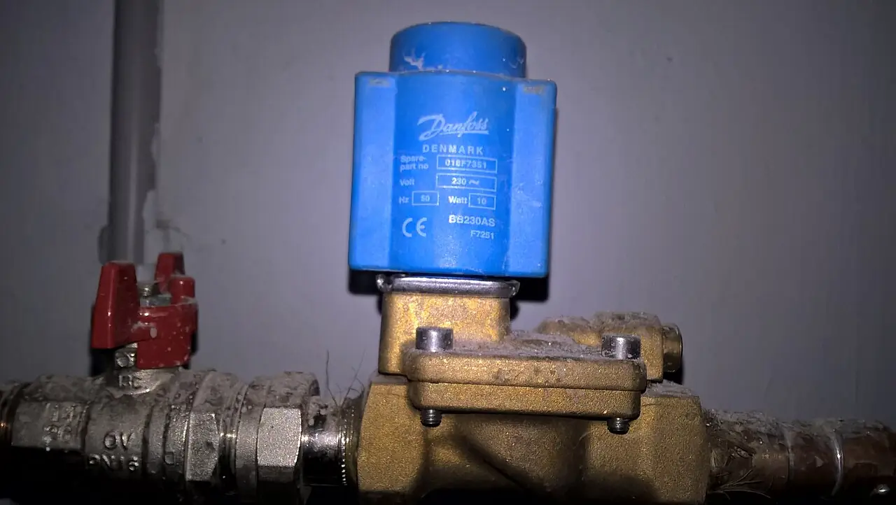
The family tree starts lower. A solenoid valve, like the brass two position valve in the photograph above, is fully open or fully closed and latches between those two states; it meters nothing in between. The servo valve is the fully proportional descendant: instead of a coil pulling an armature against a spring to two end positions, a torque motor holds any intermediate position on command, and the second stage spool follows continuously. Buyers migrating from switching valves sometimes underestimate what proportionality costs in cleanliness and setup discipline, and the rest of this page is largely about those two subjects, because they decide the cost of ownership more than the purchase price ever does.
In the machine, the servo valve sits between a hydraulic power unit and a hydraulic actuator. The controller computes a motion command, a servo amplifier converts it to coil current, the valve meters oil, and the actuator converts flow into velocity and force; a sensor on the actuator returns position, velocity, or force to the controller, closing the outer loop. The valve is the highest bandwidth element in that chain, which is why loop designers size the rest of the system around it. The power unit behind the valve matters just as much: a fixed displacement pump over a relief valve, or a variable displacement pressure compensated pump, sized for the sum of valve flow and quiescent pilot leakage, with a cooler that carries standby heat as well as peak duty.
What is actually being decided in this purchase is a set of commitments. First, necessity: whether the loop truly needs servo class bandwidth and resolution, because a well applied proportional valve closes most industrial motion loops at a third of the cost. Second, architecture: nozzle flapper, jet pipe, or direct drive, each with different contamination sensitivity and null leakage. Third, the numbers: rated flow at 70 bar per metering land, supply pressure range, bandwidth, resolution, hysteresis, and the internal leakage the machine can live with. Fourth, the lifecycle commitment: ISO 4406 cleanliness class, filtration rating, and the sampling program that keeps the fluid there for years. Fifth, integration: command signal, feedback outputs, connector, mounting subplate, and the amplifier or driver electronics that feed the coils. A quotation that answers only the numbers has priced a component, not a servo system.
Four documents organize the datasheet. ISO 4406 defines the cleanliness codes, the three number ratings such as 15/13/10, that hydraulic suppliers quote as a condition of warranty; a flapper type servo valve typically demands 15/13/10 or cleaner, and aerospace practice tightens toward 14/11/8. ISO 10770-1 and ISO 10770-2 define the test methods for four way and three way electrohydraulic control valves, the basis behind any published flow gain, pressure gain, and hysteresis figure. SAE ARP475 collects servo valve qualification testing practice, and MIL-V-27161 is the legacy military specification that some older programs still cite by contract. A datasheet quoting none of these is a price tag with numbers no test backed.
The RFQ should also state where this valve is not the answer, because servo hydraulics is one actuation world among several. On process lines, a conventional control valve throttling steam or water, positioned by a valve positioner fed from an I/P converter, serves loops whose time constants are seconds rather than milliseconds; that pneumatic world has its own standards and its own economics. On machine loops needing small forces at modest speed, a pneumatic actuator or an electric actuator removes the hydraulic infrastructure entirely. Within hydraulics, plain directional valves with solenoid operators cover switching duty at a fraction of the price. The servo valve is bought when bandwidth, force density, and stiffness together rule out every cheaper path, and chapter 5 draws those lines quantitatively.
Chapter 2 / 06
How the Torque Motor, Pilot Stage, and Feedback Loop Work
The first stage of a flapper type servo valve is a torque motor: a permanent magnet circuit, a wound armature suspended on a thin flexure tube between pole pieces, and two coils. Coil current, typically plus or minus 10 mA at the coil or plus or minus 10 V at the amplifier input, torques the armature a fraction of a degree. The armature carries a flapper that sits between two opposed nozzles; when the flapper moves closer to one nozzle, the flow restriction raises pressure behind that nozzle and drops it behind the other, creating a differential pressure across the ends of the second stage spool. The flexure tube seals the torque motor from the hydraulic fluid, which is why the electrical side survives a life immersed in oil on the other side of a thin metal tube.
The second stage is a four way spool in a precision sleeve, with lap widths of a few microns controlling null behavior. With the spool displaced, one metering land opens supply to one actuator port while another land opens the opposite port to tank, and flow follows the orifice law: proportional to spool displacement and to the square root of the pressure drop. The rating convention the whole industry uses quotes rated flow at 70 bar drop per metering land, so a 40 L/min valve delivers 40 L/min with 70 bar taken across each metering edge at full command; common frames run 4, 10, 20, 40, 60, and 100 L/min, and the 761 series class extends beyond 250 L/min at larger sizes. Supply pressures span 70 to 315 bar in standard hardware, and the maker's cavitation curves derate usable drop at the top of that range.
Feedback is what makes the device a servo. In the flapper architecture, a thin spring wire connects the spool to the flapper: as the spool moves, the wire deflects the flapper back toward center, restoring nozzle balance when spool position corresponds to command current. The result is force balance: spool position holds itself proportional to coil current with resolution better than 0.1 percent of rated travel, hysteresis under 2 percent, and symmetrical flow gain in both directions. In direct drive valves the same job is done electrically: an LVDT measures spool position, and valve driver electronics close the position loop at kilohertz rates, which permits null adjustment and characteristic shaping in software instead of by lapping sleeves in the factory.
Null behavior deserves its own paragraph because it drives both the power unit and the purchase decision. A flapper pilot passes continuous nozzle flow whenever supply pressure is on, and at null, meaning zero command and zero load flow, that flow returns through the tank gallery as internal leakage of typically 0.5 to 3 L/min depending on frame size and supply pressure. The quiescent leak is why servo hydraulic power units run warm at standby and why their coolers are sized for standby as well as peak duty. A direct drive valve, needing no pilot flow, sits near zero internal leakage at null, which is one reason it has displaced flapper types on machines that dwell at standby for long periods between moves.
Dynamic response separates the architectures in numbers. A flapper type servo valve behaves as a second order element whose dynamics the manufacturer publishes as amplitude ratio and phase lag versus frequency; families run 150 to 400 Hz for nozzle flapper hardware in the common frames, and the catalog number falls as frame size rises. Direct drive valves, limited by force motor and spool mass, deliver 50 to 150 Hz class response. The loop designer matches valve bandwidth to load dynamics with the working rule that the valve should be at least three to five times faster than the natural frequency of what it commands; stating a bandwidth requirement in the RFQ keeps suppliers honest about which architecture they are actually offering.
Dither is the last mechanism and the most misunderstood. A small amplitude, high frequency current, commonly in the 200 to 500 Hz range at a few percent of rated command, is superimposed on the command signal by the amplifier. The intent is to keep the spool microscopically in motion so that silt cannot bridge the sleeve clearance and stiction never develops at null. Dither amplitude is tuned at commissioning: too little and null performance degrades between services, too much and the actuator hums while metering edges wear. The RFQ should state whether dither is factory set or field adjustable, and commissioning records should capture the final values, because those settings belong to the loop identity as much as any gain in the controller.
Chapter 3 / 06
Pilot Architectures, Construction, and Duty Boundaries
The nozzle flapper two stage valve is the classical servo valve and remains the precision benchmark. Its pilot clearances are small: nozzle to flapper gaps sit in the tens of microns, and sleeve to spool radial clearances in the 1 to 4 micron class. That geometry buys resolution and repeatability, and it prices the valve in fluid cleanliness: the pilot stage demands servo grade filtration, typically 3 micron absolute in the pressure line feeding the valve, with 10 micron return line filtration as the system floor. Machines that cannot maintain that discipline should buy a different architecture, not a finer valve that dies faster.
The jet pipe variant replaces the opposed nozzles with a single pressure jet deflected by a pipe nozzle into two receiver holes. The pilot flow is higher and the internal passages are larger, so a jet pipe stage tolerates coarser fluid than a flapper stage, at slightly higher quiescent consumption and with comparable achievable bandwidth. Jet pipe designs also fail more gracefully: a flapper valve can drive hard over if a nozzle plugs, while a jet pipe upset tends to be recoverable once the blockage clears. Steel mills and marine steering gear, where maintenance windows are short and fluids are real world, remain jet pipe strongholds for exactly these reasons.
The direct drive valve, DDV in supplier shorthand, eliminates the pilot entirely. A linear force motor, a voice coil class device with high force density, pushes the spool through its travel, and an LVDT reports position to driver electronics that complete the loop. With no pilot flow, null leakage is near zero; with no micron scale nozzle, contamination tolerance approaches general industrial hydraulics; and the valve accepts industrial command standards, plus or minus 10 V and 4 to 20 mA, without a separate servo amplifier. The bandwidth tax, 50 to 150 Hz class, is the trade, and most machines except high rate test and vibration duty run comfortably inside it. The D633 and D634 hardware class is the market reference for this architecture, and the E024 class scales the same principle down to micro flows.
Construction details are shared across the family. Bodies are machined steel with internal drillings, subplate mounted so the valve unbolts without breaking lines, with mounting patterns per ISO 4401 sizes 03 through 10 as the industrial norm and maker specific subplates on aerospace frames. Spools and sleeves are hardened and lapped in matched sets; torque motor coils come in single, dual, and differential configurations; and electrical entry runs through threaded circular connectors, with the connector standard a line item because adapters change both maintenance access and certification status. Around the valve, bench and gauge plumbing stays manual: a needle valve in gauge and bleed circuits handles slow release and venting where metering by hand is wanted.
Boundaries are worth stating bluntly. The servo valve is not a switching device: two position duty belongs to a solenoid valve at a tenth of the price and none of the cleanliness discipline. It is not a process control element: throttling steam, water, or chemicals belongs to a control valve working with its valve positioner, commanded through an I/P converter in the pneumatic world, with a globe control valve trim when the pressure drop is severe; hydraulics earns its keep on force density and speed, not on metering process fluids. And it is not forgiving of dirty oil: no filtration program means no servo valve, regardless of which architecture the RFQ names.
Architecture
Pilot principle
Feedback
Bandwidth class
Null leakage
Contamination posture
Nozzle flapper two stage
Torque motor, flapper between opposed nozzles
Mechanical feedback wire
150 to 400 Hz
0.5 to 3 L/min
Demands 15/13/10 or cleaner, 3 micron absolute pressure filtration
Jet pipe two stage
Torque motor, deflected jet into two receivers
Feedback wire or spring
Comparable class, typically slightly below flapper
0.5 to 2 L/min class
Larger passages, tolerates coarser fluid
Direct drive single stage (DDV)
Linear force motor on spool, no pilot
LVDT electrical in driver
50 to 150 Hz
Near zero
Industrial grade, no pilot clearances to silt
Chapter 4 / 06
Key Specification Parameters
The table below decodes the datasheet lines that decide whether a quoted valve matches the loop. Each row is purchase defining; the paragraphs after the table explain what to demand and what a weak answer looks like.
Attribute
Typical range or options
What it decides
Rated flow at 70 bar per land
4, 10, 20, 40, 60, 100 L/min common; 250+ large frames; micro frames to about 5 L/min
Actuator velocity and the pump and cooler sizing behind it
Supply pressure range
70 to 315 bar standard hardware
Force capability and the cavitation derate at high drop
Command signal
Plus or minus 10 mA coils; plus or minus 10 V; 4 to 20 mA industrial
Amplifier or driver selection and the controller interface
Feedback type
Mechanical wire; LVDT with driver electronics
Linearity, null stability, and in service adjustability
Bandwidth
Flapper 150 to 400 Hz; DDV 50 to 150 Hz
Achievable loop gain without instability
Resolution and hysteresis
Under 0.1 percent resolution; under 2 percent hysteresis
Smallest repeatable move and positioning accuracy
Internal leakage at null
Flapper 0.5 to 3 L/min; DDV near zero
Standby heat, cooler duty, and energy draw
Cleanliness class
ISO 4406 15/13/10 typical demand; 14/11/8 aerospace practice
ISO 4401 subplate sizes 03 to 10; threaded ports on small frames
Subplate or manifold pattern and interchangeability
Electrical entry
Threaded circular connectors per maker standard
Adapter inventory, maintenance access, hazardous area fit
The flow rating row carries the most misuse. A supplier quoting rated flow at 70 bar total valve drop instead of per metering land flatters the valve by about 40 percent, and two quotations that look identical then are not. State the convention in the RFQ and hold every quotation to it, then demand the flow gain curve, flow versus command at fixed drop, because the curve exposes symmetry and linearity that a single number hides. Size against actuator velocity at the worst credible supply pressure, not the nominal header pressure, because pump droop under simultaneous axis motion is where machines actually run.
Command signal rows decide the electrical package. Flapper coils in the plus or minus 10 mA world need a servo amplifier with tuned current feedback; direct drive valves carry their own driver and accept plus or minus 10 V or 4 to 20 mA directly. On hazardous area installations the command loop goes through a safety barrier certified for the zone, and the barrier's series resistance must be inside the coil circuit budget; a barrier chosen after the amplifier is a redesign. Coil configuration, single, dual for redundancy, or differential, belongs in the same paragraph of the specification because it changes both the amplifier and the failure monitoring.
The instrumentation around the valve decides whether any of these numbers are ever seen. A pressure transmitter on the supply line close to the valve captures droop and transients that otherwise appear only as unexplained loop faults; a differential pressure transmitter across the pressure filter announces element loading before the bypass cracks and quietly feeds the valve dirt; a temperature transmitter on the reservoir tracks the viscosity window, because fluid thinned beyond its grade shifts null and damping; and on test stands a flow meter in the return line verifies rated flow during acceptance. Where the power unit runs a sealed, slightly pressurized reservoir, an absolute pressure transmitter on the reservoir verifies the blanket setting instead of guessing at it. Budget these instruments in the same purchase order as the valve, because retrofit wiring never happens on time.
Standby energy is a specification item, not an afterthought. A flapper valve's quiescent leak pushed across a relief valve converts directly into heat, so power units increasingly drive the pump motor through a VFD to unload at standby, or at minimum through a soft starter to limit inrush on machines that stop and start the motor between cycles. Either device belongs in the hydraulic package RFQ, not in a later electrical change order. The comparison table below compresses the architecture decision into the rows a specification meeting can argue from.
Parameter
Nozzle flapper
Jet pipe
Direct drive DDV
First stage
Opposed nozzles and flapper
Deflected jet into receivers
None, force motor direct on spool
Feedback
Mechanical wire to flapper
Wire or spring to pilot
LVDT closed in driver electronics
Bandwidth class
150 to 400 Hz
Comparable, slightly lower typical
50 to 150 Hz
Null leakage
0.5 to 3 L/min
0.5 to 2 L/min class
Near zero
Contamination sensitivity
Highest, micron clearances
Moderate, larger passages
Lowest, no pilot stage
Best duty
Test rigs, vibration, flight control class
Steel mills, marine, plants with real world fluids
Injection molding, general motion, standby heavy machines
Chapter 5 / 06
Selection Decision Factors and RFQ Language
The decision sequence is short enough to run as a checklist in a specification meeting, and each step eliminates a class of quotations before price comparisons begin.
Verify the loop needs it: state required bandwidth, resolution, and force density. If a proportional valve closes the loop at a third of the cost, it is the correct purchase.
Choose architecture against the fluid reality: flapper for precision and clean laboratories, jet pipe for plants with real world maintenance windows, direct drive for general motion and standby heavy machines.
Fix rated flow at 70 bar per metering land against actuator velocity, with supply droop margin under simultaneous axis motion.
Fix command and driver: coil current or voltage command, 4 to 20 mA where the control system speaks it, amplifier or integrated driver, and the dither policy.
Set the cleanliness contract: ISO 4406 class at commissioning and in service, 3 micron absolute pressure filtration with stated beta ratio, and the sampling interval.
Set the null leakage allowance and its consequences: standby heat, cooler duty, and the energy picture of the power unit.
Define integration: subplate standard, connector, feedback and monitor outputs, and hazardous area barriers where the area classification demands them.
Demand test evidence: flow gain, pressure gain, hysteresis, and frequency response per ISO 10770 methods, with the acceptance run logged against a flow meter on the test stand.
Against neighboring actuation hardware, the honest comparison runs as follows, and it belongs here in the selection chapter rather than in the page title. A proportional valve closes most industrial motion loops at 30 to 60 Hz for about a third of the cost, with coarser resolution and far better contamination tolerance; the servo premium is bought for bandwidth and precision, not prestige. A globe control valve with a valve positioner, fed by an I/P converter, is the process world's instrument for throttling steam and liquids on loops counted in seconds. A pneumatic actuator serves low force, clean utility motion, and an electric actuator serves slow, low force axes where hydraulics cannot justify a power unit; a hydraulic actuator remains the only answer when compact force in the 10 to 100 kN class and fast response must coexist, and the servo valve is the instrument that aims it. For two position switching, a solenoid valve does the job without cleanliness overhead. On the power unit, the pump motor's VFD or soft starter decision is an energy line item, and on hazardous area skids the safety barrier between controller and coils is a certification line item.
The application map below turns those boundaries into a table the project file can carry.
Application
Construction to specify
Check before order
Fatigue and materials test rig
Nozzle flapper two stage, 150 to 400 Hz class, laboratory filtration skid
Direct drive DDV, 4 to 20 mA command, near zero null leakage
Standby heat budget; driver integration to the machine control
Steam turbine governor
Flapper or jet pipe per OEM schedule, redundant coils
Governor test evidence; environment protection class
Flight simulator motion base
Flapper class bandwidth on a dedicated filtration skid
Axis resonances versus valve bandwidth; failure monitoring
Marine steering gear
Jet pipe or DDV with coarse fluid tolerance
Classification society approval; shock and vibration qualification
The RFQ block should be written once and reused. A complete block reads: quantity and tag list; architecture named; rated flow at 70 bar per metering land; supply pressure range; command signal and connector standard; feedback type and monitor outputs; bandwidth requirement with test basis; resolution and hysteresis guarantees; null leakage allowance; ISO 4406 cleanliness class commitment with filtration ratings and beta values; null characteristic; subplate standard; dither provision; certificates and test data per ISO 10770 methods; and spares policy covering coils and filter elements. A quotation returned without the flow gain curve, the hysteresis figure, and a stated cleanliness condition is incomplete at any price.
Chapter 6 / 06
Installation, Standards, Failure Modes, and Maintenance
Installation quality decides whether the valve ever sees its rated life. The hydraulic system is flushed to the target cleanliness class before the servo valve is bolted on: loops are bridged, a temporary flush filter runs, and particle counts are taken at the valve subplate port, because fitting debris, hose swarf, and welding scale kill pilot stages in the first hundred hours more reliably than any other cause. Never flush through the valve and never deadhead the pump against a closed servo circuit: bypass the valve, or stroke it only under the maker's written procedure. Subplate faces are cleaned with lint free wipes, O rings lubricated with system fluid, and mounting bolts torqued to the maker's table, because a distorted subplate is a distorted sleeve.
Commissioning sets three numbers and records them. The null is adjusted so zero command yields zero load flow, using the maker's procedure with gauges across the actuator ports. Dither amplitude and frequency are set and written down as part of the loop identity. Quiescent leakage is measured at supply pressure and logged as the health baseline, and the acceptance run logs command against a flow meter so rated flow is proven, not promised; a pressure transmitter trend on the supply line during first full stroke captures droop and ringing that later faults will be judged against. The hydraulic fluid is certified by particle count before the first commanded cycle, and the certificate goes into the valve's file with the commissioning sheet.
The standards frame is short and worth quoting in the RFQ. ISO 4406 defines the cleanliness codes and their counting basis. ISO 10770-1 and ISO 10770-2 define the test methods for four way and three way electrohydraulic control valves, the basis of published performance. SAE ARP475 collects servo valve test practice. MIL-V-27161 remains the legacy military reference some programs inherit by contract. Filter elements are rated by beta ratio under ISO 16889, and the purchase should state the beta value behind the micron rating so that a 3 micron claim means the same thing from two suppliers.
Failure modes follow a short, contamination led list. Silting lock at null: silt bridges the sleeve clearance and the valve loses resolution or sticks at center; dither and clean fluid are the preventives. Spool scoring and seizure: hard particles engrave the spool, leakage rises, and the valve comes out on a scheduled exchange rather than an in place rebuild. Torque motor burnout: overcurrent from a miswired amplifier or a faulted driver cooks the coils; the fix is electrical discipline, not a better valve. Feedback wire fatigue: sustained oscillation, from an unstable loop or structural vibration transmitted through the piping, work hardens the wire until it snaps, and the symptom is a valve that drifts or drives hard over. Erosion, the wire drawing of metering edges: high pressure drop with dirty fluid cuts sharp lands into washouts, read as rising null leakage. Cavitation at high drop: derate per the maker's curves when taking large drops at high supply pressure.
Maintenance is a fluid program with a valve attached. The differential pressure transmitter on the pressure filter is the standing alarm: elements change at the maker's terminal delta, never riding the bypass. Fluid is sampled quarterly to semiannually and trended against the ISO 4406 commitment, because a trend, not a snapshot, is what the warranty argument will use. A temperature transmitter reading that creeps upward at standby indicates cooler fouling or rising internal leakage. On power units with pressurized reservoirs, an absolute pressure transmitter verifies the low positive blanket that keeps air and moisture out of the oil. On machines with cycling motors, the soft starter or VFD contactor state belongs in the same health log, and case drain lines are vented through a needle valve at service so trapped air leaves the circuit under control. Around gauge and sample points, small hardware, a ball valve and a check valve at each tap, lets instruments be changed without draining the line, and a pressure gauge on the pump outlet remains the first diagnostic anyone reaches for. At the valve itself the annual check is null drift, quiescent leakage against the commissioning baseline, and coil resistance and insulation; a rising leak number on a clean fluid trend is the machine saying which spare to order.
Close the lifecycle with records the next purchase can use. Keep the cleanliness certificates, commissioning baseline, dither settings, filter trends, and annual checks in one file per tag, and when the next axis is specified, that file converts supplier claims into line items: measured standby heat sets the power unit design, leakage history sets the architecture choice, and the fluid trend sets the filtration budget. A servo hydraulic plant without those numbers is paying servo prices for fortune telling.
FAQ
What service actually requires a servo valve?
Specify a servo valve when the motion loop needs bandwidth above roughly 60 Hz, resolution finer than about 0.1 percent of travel, or the force density that only hydraulic actuation delivers: materials and fatigue test rigs, flight simulator motion platforms, steel mill gauge control, high rate injection molding, turbine governing, and precision marine steering. Below those demands a proportional valve closes most industrial loops at about a third of the cost, with better contamination tolerance and no servo grade filtration commitment.
How is rated flow specified and why does the convention matter?
Rated flow is quoted at a 70 bar drop per metering land at full command. A 40 L/min valve delivers 40 L/min only under that convention; a supplier quoting total valve drop instead of per land flatters the valve by about 40 percent, and two quotations that look identical then are not. State the convention in the RFQ, demand the flow gain curve, and size against actuator velocity at the worst credible supply pressure, not the nominal header pressure.
Why does the datasheet obsess over ISO 4406 cleanliness?
Cleanliness is the lifecycle specification because the failure modes that end servo valve life are contamination driven. Codes such as 15/13/10 describe particle counts above 4, 6, and 14 micron; flapper stages need that class or cleaner, and aerospace practice tightens toward 14/11/8. The commitment buys 3 micron absolute pressure filtration, return line filtration, and a sampling program. Without it the warranty is void in letter and the valve is consumed early in fact.
What is dither and who sets it?
Dither is a small amplitude, high frequency current, commonly 200 to 500 Hz at a few percent of rated command, superimposed by the amplifier to keep the spool microscopically moving so silt cannot bridge the sleeve clearance. Amplitude is tuned at commissioning: too little invites null silting, too much hums the actuator and wears metering edges. The RFQ should state whether dither is factory set or field adjustable, and commissioning should record the final values.
How much internal leakage is normal at null?
A flapper or jet pipe pilot consumes continuous nozzle or jet flow, which at null, zero command and zero load, returns to tank as internal leakage of 0.5 to 3 L/min depending on frame size and supply pressure. That quiescent flow sets standby heat and cooler sizing. A direct drive valve needs no pilot flow and sits near zero at null. Measure leakage at commissioning as the baseline, because a rising trend on clean fluid predicts erosion or wear before the loop complains.
What failures dominate servo valve life?
Contamination leads every list: silting lock at null, spool scoring, and wire drawing erosion of the metering edges. Electrical faults follow: torque motor burnout from overcurrent and driver failures. Mechanical fatigue closes the set: feedback wire snap from sustained oscillation or transmitted vibration. Cavitation damage appears where large drops are taken at high supply. A quarterly fluid sample, a filter differential alarm, and an annual null and leakage check catch nearly all of these before they become unplanned stops.
What belongs in the servo valve RFQ block?
Architecture, nozzle flapper, jet pipe, or direct drive; rated flow at 70 bar per metering land; supply pressure range; command signal and connector; feedback type and monitor outputs; bandwidth, resolution, and hysteresis guarantees with test basis per ISO 10770 methods; null leakage allowance; ISO 4406 cleanliness commitment with filtration ratings and beta values; subplate standard; dither policy; and certificates. A quotation without the flow gain curve and a stated cleanliness condition is incomplete at any price.