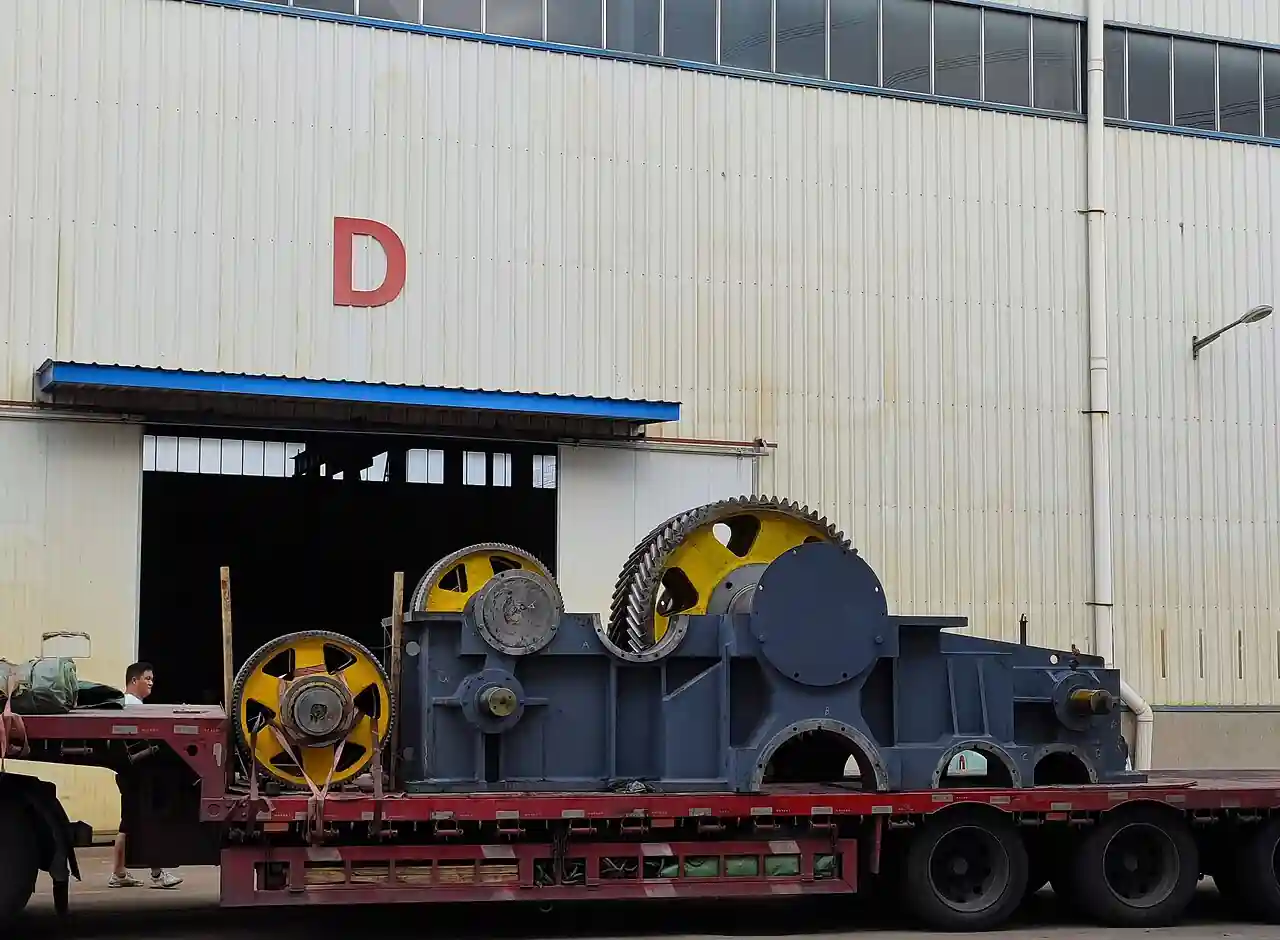
A turboexpander is a turbine that extracts work from a high pressure process gas by expanding it, dropping both the gas pressure and its temperature as the rotor spins, and putting the recovered power to use on the same shaft, most often driving a centrifugal compressor stage in gas processing service. Where a control valve wastes letdown pressure as noise and heat, an expander turns most of it into refrigeration and shaft work, which is why it sits at the heart of natural gas liquids recovery, dew point control, and cryogenic gas plants. Atlas Copco Gas and Process and Chart Industries are the reference vendors of the class, and this page treats the expander and its loaded train as the purchasing object.
This page is written for the engineer specifying an expander for gas processing, dew point control, or energy recovery duty. It works through how the expansion actually produces cold and power, which loading and bearing configurations fit which plants, the parameters on vendor data sheets, and the selection factors and RFQ language that decide whether the installed machine meets its efficiency and recovery guarantees.
The decision concentrates in five places: the gas composition and its inlet pressure and temperature, the expansion ratio and outlet condition the process needs, the shaft loading, compressor, generator, or brake, the bearing and seal class the speed and gas demand, and the condensation behavior at the rotor exit. Get those right and the frame size, speed, and skid follow.
Chapter 1 / 06
What a Turboexpander Is and What Is Being Decided
The industrial machine this page describes is a radial inflow turbine: gas enters the casing, is accelerated through a ring of stationary nozzles, often adjustable inlet guide vanes, and directed onto the blades of a single high speed rotor wheel, whose spinning extracts energy as the gas spirals inward and decelerates into the discharge collector. Radial inflow geometry dominates because it tolerates high expansion ratios per stage with compact rotors; the wheel runs on shaft speeds of tens of thousands of revolutions per minute on process machines. The power leaving the rotor shaft must go somewhere, and the machine is defined as much by its load as by its turbine: an expander compressor bolts a centrifugal compressor wheel to the opposite shaft end, an expander generator couples the shaft to an electrical machine through a gearbox or a high speed generator, and older small units simply burn the power in an oil brake.
What is being decided when a turboexpander is purchased is a recovery guarantee in two currencies at once: refrigeration, the cold produced by the expansion, and shaft power, the work delivered to the load. The buyer is purchasing a stated isentropic efficiency on a stated gas and a stated operating envelope, delivered continuously, with the process benefit that follows, higher liquids recovery, a met hydrocarbon dew point, or exported electricity, depending on the plant. Everything on the vendor data sheet, flow range, pressure ratio, speed, power, efficiency, bearing and seal class, exists to support that guarantee, and the five decisions this page works through determine whether the installed machine holds it across the plant's operating year.
The turboexpander occupies a precise place in the rotating machinery landscape and its boundaries matter. It is not a centrifugal compressor: that is the driven machine that raises gas pressure, and it appears in this story as the load on the expander's other shaft end rather than as a competitor. It is not a steam turbine: a steam turbine expands water vapor on a Rankine cycle with its own boiler and condensing plant, and the steam turbine page on this site states plainly that it is not a gas turbine or a gas expander. It is not a turbo blower, which is a low pressure air machine on a completely different duty. And it is not the Joule Thomson valve it replaces: the valve expands the same gas to the same outlet pressure with no work extraction and therefore less refrigeration, and the expander's whole economic case is the difference between those two outlet temperatures.
Different buyers buy the same machine for different reasons. A gas processing plant buys an expander compressor to deepen ethane and propane recovery, dropping the gas across the machine into a distillation column cold section that a valve alone could not reach. A pipeline or storage operator buys expander duty for hydrocarbon dew point control, meeting a gas quality specification while recovering power instead of wasting it. An air separation or LNG plant buys cryogenic expanders as refrigeration machines at the heart of the cold box. A compressed air or chemical plant with a large steady letdown buys generator loaded machines that export electricity from pressure it already owns. The specification language differs, but the rotor physics is shared.
A short tour of named duties makes the machine concrete. In a deep NGL recovery plant, residue gas from a molecular sieve dehydrator expands through the machine into the demethanizer column, the expander's compressor end recompresses the column overhead, and a dew point transmitter confirms the treated gas meets its water and hydrocarbon spec downstream of the glycol or molecular sieve cleanup. In a dew point control skid at a pipeline station, a knockout drum and a coalescing filter clean the feed, the expander drops the gas across the specification point, and a heater or the discharge line thaws it back to pipeline temperature. In an LNG peakshaver, a nitrogen or methane expander closes the refrigeration balance of the cold box. In each duty the same five knobs appear: inlet conditions, ratio, load, bearings, and condensation.
The purchase is always a process integration, not an isolated machine, and the RFQ that treats it as a box misses its value. The expander's feed must be clean and dry, because the very cold it creates condenses every contaminant the gas carries: upstream solids removal by filtration, liquid removal by a knockout drum and a mist eliminator, and dehydration by a glycol dehydrator or a molecular sieve dehydrator decide whether the nozzles and rotor run for years or foul in months. The process control around the machine, the guide vane and recycle logic that keeps it on its envelope as the plant swings, is as much a part of the product as the rotor.
Chapter 2 / 06
How Expansion Does the Work
The physics is isentropic expansion with real machine losses. Gas at high pressure enters the nozzle ring, where roughly half the enthalpy drop converts to velocity; the rotor then extracts that kinetic energy plus a further pressure drop as it turns the flow inward, and the gas leaves the wheel cold, slow, and at the discharge pressure. An ideal expansion would follow the constant entropy line, and the ratio of actual enthalpy drop to ideal drop is the isentropic efficiency that vendors quote, typically in the low to mid eighties in percent for well designed process expanders. Every point of that efficiency is refrigeration or shaft power, which is why it is the guarantee number.
The temperature drop is the process payoff. Expanding a typical natural gas from 60 bar to 20 bar at an inlet near ambient can drop the outlet tens of degrees below zero, and the expander outlet is deliberately colder than a valve outlet for the same boundary conditions, because the work extracted leaves the gas. That cold condenses the heavier components the plant wants as liquids: in NGL service the two phase stream leaves the expander and feeds the cold section of a fractionation column, and the recovery of ethane and heavier components is set directly by how cold the expander can take the gas within the methane rejection or recovery spec the market sets. Plants that let a valve take the same letdown recover less, and the difference is the expander's entire business case.
Shaft power is the second currency, and it must balance at every operating point. The rotor absorbs the turbine power, the load consumes it, and the machine's control keeps the two equal: an expander compressor absorbs power by raising gas pressure at its wheel, and its surge and choke limits define the combined operating envelope; an expander generator exports to the grid through power electronics or a synchronous machine with speed control; a brake simply burns the power in oil. Compressor loading dominates gas processing because the recompression is needed anyway, making the expander compressor pair one thermodynamic machine with two wheels, and the vendor's guarantee covers both ends.
Speed, bearings, and seals set the mechanical class. Rotors on process expanders run anywhere from roughly ten to more than fifty thousand revolutions per minute depending on size, speeds at which bearing and rotor dynamics are the design core. Oil film bearings are the long standing solution, with a lube oil skid, seals that isolate the oil from the process gas, and fire and contamination considerations that follow; active magnetic bearings eliminate the oil entirely, levitating the shaft on controlled electromagnets, and have become the preferred class on many cryogenic and export power machines because they remove the lube system from the cold box and the gas from the oil. Dry gas seals or labyrinth seals isolate the process, with seal gas supply conditioning of its own.
Condensation inside the rotor is a designed condition, not an accident. Many expander duties intentionally run the expansion into the two phase region, with several percent mass of liquid present at the wheel exit, and the rotor geometry, blade counts, and exit dimensions are designed for dense wet flow without blade erosion at those liquid fractions. What the machine does not forgive is liquid or solids ahead of the nozzles: droplets that flash in the nozzle throat and dust that plate out on the vane surfaces change the flow angles and eat the efficiency, which is why the upstream cleaning train and a fine filter immediately ahead of the machine are part of the specification, and why a differential pressure indication across that filter is part of the instrument list.
Guide vanes and antisurge logic let the machine live in a real plant. Adjustable inlet guide vanes shift the nozzle flow angle and the machine's flow capacity, holding efficiency across a range of process rates that a fixed nozzle would meet only at one point. On compressor loaded machines, the compressor end's surge line is protected by a recycle or hot gas bypass that keeps the compressor flow above its limit while the expander side follows the process, and the combined control, vane position, recycle valve, and speed where applicable, is commissioned as one system. A vibration sensor set on the shaft and casing, temperature measurements on bearings and discharge, and pressure and temperature at inlet and outlet land in the control system, and a plc or the plant DCS runs the protective trips that shut the machine down faster than an operator could.
Chapter 3 / 06
Loading Types, Bearings, and Duty Boundaries
The expander compressor is the canonical form: one shaft, expander wheel on the cold end, centrifugal compressor wheel on the warm end, power flowing continuously from one to the other with no lossy conversion step. The compressor end is usually the process's own recompression stage, as in NGL recovery where it pumps the demethanizer overhead back toward pipeline pressure, and its wheel can be one or two stages. The machine's guarantee is a combined statement, expander efficiency and compressor performance, and the buyer should insist on the envelope map that shows where the pair runs across the plant's turndown.
The expander generator converts the recovered power to electricity, either through a gearbox to a conventional generator or through a direct coupled high speed generator with power electronics. It suits letdowns where the process has no use for recompression: pipeline pressure letdown, storage withdrawal, and export duty at chemical plants. The electrical scope, synchronization or inverter, grid interface, and protection, is a project in itself and often the schedule driver, and the machine's value is set by the power price and the plant's running hours. The oil brake, historical and now rare, burns the power into a lube oil loop for small machines where neither load is worth the hardware; it survives where capital must be minimum and power recovery does not pay.
Configuration
Load on the shaft
Typical duty
Where it wins
Expander compressor
centrifugal stage, same shaft
NGL recovery, dew point control
Recompression needed anyway, no conversion loss
Expander generator, geared
generator via gearbox
pipeline and storage letdown
Power export from pressure the plant owns
Expander generator, high speed direct
direct generator and inverter
cryogenic and export machines
No gearbox, magnetic bearing friendly
Oil brake expander
oil loop heat
small, low capital duties
Minimum hardware where power does not pay
Bearing class is the other type decision. Conventional oil bearing machines carry a lube skid with pumps, cooler, and accumulator, seal gas systems separating oil from gas, and the fire and contamination management that oil near cold gas implies. Magnetic bearing machines carry a control cabinet instead, levitate the shaft with no oil anywhere near the process, tolerate the cold box environment naturally, and often integrate the high speed generator on the same levitated shaft. The trade is capital and electronic complexity against the elimination of an entire utility; on cryogenic skids and offshore modules the magnetic choice has become the default, while many plant machines still run happily on oil.
Duty boundaries against the neighbors deserve plain language. When the requirement is to raise gas pressure, the machine is a centrifugal compressor, driven here by the expander end but existing as its own product class. When the working fluid is steam on a condensing or backpressure cycle, the machine is a steam turbine, which this site's steam turbine page already covers as its own authority. When the duty is low pressure air delivery, the machine is a turbo blower. When the requirement is only to waste pressure safely, a control valve does the job, and the expander's business case is built precisely on refusing to do that: the cold and the power are the product. Around the expander, the plant neighbors are its life support, the knockout drum and coalescing filter that keep the feed dry of droplets, the molecular sieve dehydrator upstream that keeps it dry of vapor, and the mist eliminator that protects the cold column it feeds.
Chapter 4 / 06
Key Specification Parameters
Vendor quotations revolve around a compact parameter set that a buyer can compare across manufacturers on engineering terms. The table below collects the parameters that decide performance for mainstream process expander duty, with the ranges a reviewing engineer should expect across the class from small skid machines to large plant trains.
Parameter
Typical specification range
What it decides
Gas flow range
roughly 5,000 to 500,000 Nm3/h
Frame size and nozzle area
Inlet pressure
10 to 100 bar class
Available expansion work per unit flow
Inlet temperature
ambient to about 100 C common
Outlet temperature reach and materials
Expansion ratio
about 2 to 8 per machine
Temperature drop and power produced
Rotordynamic speed
10,000 to 60,000 rpm class
Bearing class, rotor stress, gearbox need
Shaft power
100 kW to beyond 15 MW
Load sizing, electrical or compressor scope
Isentropic efficiency
low to mid 80s percent
The guarantee: cold and power delivered
Outlet two phase fraction
several percent liquid by design
Recovery depth, rotor wet flow design
Bearings
oil film or active magnetic
Lube system scope, cold box suitability
Inlet guide vanes
adjustable, typical 60 to 100% flow range
Turndown efficiency and control
Seals
dry gas or labyrinth with seal gas
Emissions, oil or gas separation duty
Two of those numbers do the selection work. Expansion ratio with inlet conditions fixes the outlet temperature and the power per unit flow, and the process requirement, a recovery depth or a dew point, translates directly into them; a ratio the gas cannot deliver is a process conversation, not a vendor one. Isentropic efficiency is the value number: each efficiency point on a large machine is real money annually in recovered liquids or exported power, so the guarantee basis, the gas analysis, the inlet state, and the test tolerance, must be written with the same precision as the machine's steel.
The remainder of the parameter set carries the mechanical risk. Speed and power set the bearing and rotor class; the two phase design fraction states how wet the machine may run by design; guide vane range sets the efficiency at turndown; and the seal class sets the emissions and contamination scope. The instrumentation and control package belongs on the specification as equipment: inlet and outlet pressure and temperature, a vibration sensor set, bearing or shaft temperature, guide vane position, and the protective trip logic that acts on all of them, because the machine's protection system is what lets it run unattended through the night.
Chapter 5 / 06
Selection Decision Factors and RFQ Language
Gas definition comes first because everything inherits it. The specification should state the full gas composition including water and heavy ends, the inlet pressure and temperature across the operating year, the flow range with its normal and peak points, and the required outlet condition, a dew point, a recovery depth, or a discharge pressure for the loaded compressor end. Where the feed comes from, a pipeline, a separation train, or a storage withdrawal, sets its variability, and the contaminant inventory, dust, liquids, and hydrate formers, sets the cleaning train the expander needs upstream.
Load and utility context come second. State whether the plant wants recompression, in which case the expander compressor pair is the natural machine, or power export, in which case the generator and its electrical interface lead the project. State the site utilities: lube oil systems need cooling water or air and a fire management posture; magnetic machines need clean instrument and drive power; generator machines need a grid or island load that will take the power. Cryogenic installations add their own line, the machine's integration with the cold box and the insulation scope, which vendors package differently and the RFQ must boundary explicitly.
Selection factor
What to specify
Common mistake
Gas and envelope
composition, P and T, flow range, outlet target
Quoting a single design point with no turndown map
Loading
compressor end duty or electrical export basis
Generator project scoped without the grid interface
Upstream cleanliness
filtration, KO drum, dehydration provision
Wet or dusty feed reaching the nozzles
Bearing class
oil or magnetic with utilities to suit
Lube system scoped without cooling or fire provisions
Control integration
vane and recycle logic with the plant DCS
Antisurge and vane control split between vendors
Guarantee basis
gas basis, inlet state, test tolerance
Efficiency guarantee on an undefined gas
Scope boundary
skid, lube or MCS cabinet, electrical, cold box
Lube or seal gas systems assumed in both or neither scope
RFQ language that produces comparable offers follows from those factors and should read like a process data sheet. State the gas analysis and envelope, the required outlet condition or recovery, the loading preference with the compressor end's process duty or the electrical export basis, the upstream cleaning provided, and the bearing preference if the site has one. Ask every vendor to state the frame and wheel arrangement, the operating envelope map across the stated turndown, guaranteed isentropic efficiency on the stated basis, bearing and seal class with their utilities, the guide vane and antisurge control scope, the trip system design, and the reference machines on comparable gas and ratio.
Guarantees and acceptance close the procurement. A defensible offer guarantees efficiency and power on the stated gas and inlet state, with a defined test method and tolerance, and states the operating envelope the guarantees cover rather than a single point. Hold every bidder to the same gas basis, weight offers on annual recovered value against total installed cost including utilities and electrical scope, and include a performance test at commissioning that measures the same quantities the guarantee names, temperature drop, produced power or compressor performance, on the same instruments. The expander that misses its efficiency by two points has quietly returned the plant to valve economics.
The balance of plant the RFQ must not forget: the fine filter immediately upstream with differential indication, the seal gas supply and its conditioning, the lube oil skid or the magnetic bearing cabinet with their power quality needs, the acoustic enclosure where noise demands it, and the control integration that runs vane, recycle, and trips from the plant system. A dew point transmitter downstream closes the loop on what the machine is for, and the vibration and temperature instrumentation set lands in the historian where the condition monitoring program lives.
Chapter 6 / 06
Installation, Standards, Failure Modes, and Maintenance
Installation is a high speed machinery and piping project. The process piping on both ends must be designed for the machine's nozzle loads without transmitting strain to the casing; the lube or magnetic systems, seal gas, and electrical scope arrive as packaged skids to be set and interconnected; and cryogenic machines add the cold box, insulation, and the controlled cool down procedure that keeps thermal gradients within the rotor's allowance. Commissioning runs the machine first on its turning and protection logic, then through a staged loading that maps the actual envelope against the vendor's predicted one before the plant relies on it.
Standards shape the machine through the rotating machinery regime it lives in. Turbomachinery procurement standards govern test guarantees and the mechanical running test expectations that serious buyers witness at the vendor shop; pressure vessel and piping codes govern the casings and connections; machinery safety and area classification govern the electrical and guarding scope; and the noise enclosure often falls under plant environmental permitting. A buyer does not need to cite clause numbers to specify outcomes: name the witness test, the code stamps, and the area classification, and require the vendor's compliance map in the offer.
Failure mode
Signature
Response
Nozzle and rotor fouling
efficiency and flow drift down
Upstream filtration audit, gas cleanliness, wash or overhaul
Bearing distress
vibration and bearing temperature rise
Lube or MCS diagnostics, scheduled replacement
Seal gas failure
gas loss or oil contamination signs
Seal gas conditioning review, filter change, seal service
Verify design liquid fraction, upstream KO drum performance
Icing or hydrate blockage
sudden flow restriction in cold sections
Dehydration performance audit, warm up procedure
Routine operation is envelope led. The operators watch the machine's position on its map, inlet conditions, guide vane opening, compressor margin to surge, and the efficiency computed continuously from the instrument set, because drift in that computed efficiency is the earliest signal of fouling or wear. Condition monitoring on the vibration sensor set and bearing temperatures schedules the overhauls that high speed machines eventually need, typically measured in years of continuous running on clean gas. Seal and lube systems, filters, and the control valves of the antisurge and trip logic make up the monthly maintenance rhythm.
Overhaul and spares planning close the ownership picture on a machine whose heart is a precision rotor. Major intervals on clean, well controlled duty are measured in years of continuous running, and the overhaul scope, rotor inspection and balancing, nozzle ring renewal, seal and bearing renewal, is defined by the condition data the plant collected rather than the calendar alone. A prudent store holds the seal and bearing kits, the spare nozzle ring or the arrangements to recondition one, and the control hardware spares whose absence turns an electronic protection system into a single point of failure. On machines carrying a magnetic bearing system, the vendor's diagnostic link is part of the maintenance plan, because the same electronics that levitate the shaft watch its health every second it runs.
The measurement spine deserves its own line because an expander's value is only as good as its instruments. The gas's inlet and outlet states carry a temperature transmitter and pressure transmitter pair at each station, the flow through the machine totals on its flow meter, and from those five numbers the control system computes the efficiency that is the machine's health trend; the calibration calendar for that instrument set is, in a real sense, the guarantee's maintenance schedule. Plants that meter the machine well catch fouling and seal drift in weeks; plants that meter it poorly discover them at the overhaul.
The end state of a well specified turboexpander is a plant that gets paid twice for the same pressure drop. The gas arrives at specification, cold enough to recover the liquids or meet the dew point, the shaft delivers its power to the process or the grid, and the machine runs its years between overhauls because the feed was cleaned and the controls were commissioned as one system. The neighbors mark the boundaries: compressors raise pressure, steam turbines expand steam, valves waste it, and this machine is what buys back the energy a letdown was about to throw away.
FAQ
What does a turboexpander actually do in a gas plant?
It takes a high pressure gas stream and expands it through a turbine wheel, extracting shaft power while dropping the gas temperature tens of degrees below what a control valve would reach at the same outlet pressure. The cold condenses heavier components for liquids recovery or dew point control, and the shaft power drives a compressor on the same shaft or a generator for export. It replaces pressure letdown waste with recovered value.
Why is an expander colder than a control valve at the same outlet pressure?
Because the expander extracts work from the gas as it expands, and the energy that leaves the shaft is energy the gas no longer carries as temperature. A valve throttles the same gas to the same pressure with no work extraction, so its outlet sits on the warmer, constant enthalpy line. The temperature difference between the two outcomes is the expander's refrigeration advantage and the basis of its business case.
Should the expander be loaded with a compressor or a generator?
Compressor loading wins when the process needs the recompression anyway, as in NGL recovery where the expander's shaft drives the demethanizer overhead compressor, because power flows wheel to wheel with no conversion loss. Generator loading wins on pure letdowns, pipelines, storage withdrawal, where the recovered power is exported to the grid. The plant's process need, not the machine, makes the choice.
What gas conditions does a turboexpander need upstream?
Clean and dry to a fine standard. Solids and droplets foul and erode the nozzle ring and rotor, and the cold the machine creates condenses any vapor the gas still carries, so plants install a knockout drum and coalescing filtration immediately ahead, with dehydration by a molecular sieve or glycol system upstream of that. A fine filter with differential pressure indication right before the machine is standard practice.
How fast do these machines run, and on what bearings?
Process expanders commonly run from roughly ten to more than fifty thousand revolutions per minute depending on frame size, which makes bearing selection a core design decision. Oil film bearings with a lube skid and seal gas systems are the long standing solution; active magnetic bearings levitate the shaft electronically, eliminate oil from the process envelope, and dominate cryogenic and generator loaded machines. Both are proven classes with different utility footprints.
Can liquid be present in the machine while it expands?
Yes, by design on many duties. Expander wheels are engineered to tolerate several percent liquid mass at the exit, because the expansion intentionally runs into the two phase region to maximize recovery. What they do not tolerate is liquid arriving with the feed, droplets that flash in the nozzles and change the flow angles, or solids that deposit on the vanes; that is the upstream cleaning train's job to prevent.
What efficiency can I expect, and how is it guaranteed?
Isentropic efficiency on well designed process expanders sits typically in the low to mid eighties in percent, and it is the machine's guarantee number because every point is recovered cold or power. The guarantee must be written on a stated gas analysis, inlet pressure and temperature, and test tolerance, and verified at commissioning by measuring the same quantities, the actual temperature drop and shaft power, on calibrated instruments. An efficiency guarantee without its basis is a brochure number.