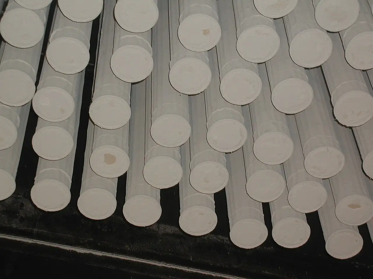
A molecular sieve dehydrator dries natural gas or similar process gas by passing it through a bed of zeolite crystals that adsorb water molecules into their precise pore structure, holding the gas to water contents far below what any liquid desiccant can reach. Two or more vertical towers alternate: one dries the gas while the others regenerate, being heated with a slipstream of dry gas to drive the water back off the zeolite, then cooled and returned to service. The cycle is temperature swing adsorption, and its product is gas at a water dew point of minus 70 to minus 100 deg C or better, the dryness that liquefied natural gas plants, deep hydrocarbon dew pointing, and cryogenic nitrogen rejection demand.
This page treats the molecular sieve dehydrator as a purchasing object: how inlet water loading and outlet specification size the beds, how regeneration gas rate and temperature set the cycle time and fuel bill, how sieve grade and inlet conditioning protect the zeolite, and how switching valves and control logic keep a batch process behaving like a continuous one. It stands beside the glycol dehydrator, which carries the pipeline-dryness duty at lower spec, and it conditions gas ahead of cryogenic plants rather than separating air like the nitrogen generator and oxygen generator that use the same zeolite family for a different job.
The decision concentrates in five places: the gas flow and its water loading, the outlet dew point the downstream process actually requires, the sieve grade and bed geometry, the regeneration gas source and its heat, and the switching valve and control architecture that cycles the towers without shocking the adsorbent. Get those right and the bed mass, cycle time, and utility duties follow.
Chapter 1 / 06
What a Molecular Sieve Dehydrator Is and What Is Being Decided
The machine is a set of pressure vessels filled with synthetic zeolite, an aluminosilicate crystal lattice with pores of molecular exactness. Type 3A zeolite has pores of roughly 3 angstroms, wide enough for a water molecule and too narrow for methane, ethane, or carbon dioxide; type 4A admits slightly larger guests; 13X, at roughly 10 angstroms, takes water and a range of larger molecules including sulfur species and carbon dioxide. Gas flowing over the bed gives up its water to those pores at the front of the bed, and a mass transfer zone, a moving band where the zeolite loads from dry to saturated, travels down the bed until it approaches the outlet. Before it breaks through, the tower switches: the loaded bed regenerates while a fresh one dries the gas.
What separates this machine from the liquid-desiccant glycol dehydrator is equilibrium depth. Triethylene glycol absorbing water reaches pipeline dryness, around 65 to 110 milligrams per standard cubic meter or 4 to 7 pounds per million standard cubic feet, comfortably; it cannot economically reach the 1 milligram class that liquefaction demands because glycol equilibrium and still-column economics fight it. Zeolite adsorption equilibrium at operating temperature sits orders of magnitude lower, which is why every lng plant, every deep dew pointing unit, and most ethylene recovery trains put molecular sieve dehydration immediately ahead of the cold box. The trade is batch mechanics and heat: beds cycle, valves switch, regeneration burns gas or steam, and the zeolite is a consumable with a life of three to seven years.
The machine is a system whose quiet parts decide its success. Upstream, a knockout drum and a coalescing filter strip free liquids and aerosols, because liquid water or glycol carryover entering a bed dumps its load on the first meters of zeolite and crushes the effective capacity; a filter doing that job badly is the single most common root cause of early bed loss. Downstream of the adsorbers, dust from attrition is caught before valves and meters. The regeneration loop is a small gas train in its own right: a slipstream of dry product gas, a heater, fired or electric, the regenerating tower, a cooler, and a condenser or separator that knocks the water out before the gas recycles or returns to fuel. Switching logic ties it together on a timer or on a computed loading model, with a dew point transmitter at the outlet as the evidence.
Buyers arrive from gas processing plants feeding lng trains, from deep dew pointing and ngl recovery, from refinery hydrogen and fuel gas systems that must protect catalyst, and from ethylene crackers drying cracked gas ahead of the cold section. All buy the same product, water so low the gas behaves like a dry gas at cryogenic temperature, and all face the same purchasing decisions: bed sizing against water loading, sieve selection against the contaminants, regeneration design against the utilities, and valve quality against a cycle that actuates thousands of times a year. The paragraphs that follow work those decisions in the order a project meets them.
Chapter 2 / 06
How Zeolite Pores, Water Loading, and Temperature Swing Do the Work
Adsorption is equilibrium physics. At a given partial pressure of water and bed temperature, zeolite holds a defined amount of water; lower temperature and higher water partial pressure push loading up, and the dynamic capacity actually usable in service is the difference between equilibrium loading at feed conditions and the residual loading left after regeneration. Typical working capacities run 8 to 14 kilograms of water per 100 kilograms of sieve depending on grade, regeneration quality, and cycle. The design calculation is bookkeeping: water in, kilograms per hour from flow times inlet content, times the adsorption hours in the cycle, plus margin for the mass transfer zone, equals the water the bed must hold, divided by working capacity gives bed mass, and bed mass with face velocity gives vessel dimensions.
The mass transfer zone is the subtlety that separates vendors. Water loads the bed through a front whose depth, a fraction of a meter to over a meter, is set by gas velocity, sieve particle size, and how far the bed is into its life, and the bed must switch before that front reaches the bottom support. Short beds with high velocity give shallow margins and early breakthrough; conservative design keeps bed depth-to-diameter ratios in the working range, face velocities around 15 to 30 centimeters per second in the settled bed, and a switch point set by calculated loading with an outlet analyzer as the tripwire. Old zeolite, its capacity half spent by heavy contaminants, shows exactly the symptom the physics predicts: the mass transfer zone lengthens and the outlet dew point creeps before the model says switch.
Regeneration is the mirror process. Hot dry gas, typically 260 to 320 deg C at the bed inlet for water service, drives the equilibrium the other way: heat the zeolite and water leaves the crystals, the carrier gas sweeps it out, and the bed returns to a low residual loading that sets the next cycle's capacity. The regeneration train heats, sweeps, cools, and dumps the water: the heater raises the slipstream, the tower takes the heat and the water, a cooler drops the gas temperature, and a separator with a level transmitter drains the condensed water while the gas recycles to fuel or feed. Heating hours, cooling hours, and switching time sum with adsorption time into the cycle, and that cycle, not the vessel, is the machine's true product: continuous dryness from a set of batch towers.
Cycle architecture is a genuine design fork. Two towers split the duty half and half, adsorption time equals regeneration time, which forces large beds when regeneration is long. Three towers decouple them: one adsorbs while two regenerate in staggered stages, letting a long hot and cool sequence coexist with steady feed. Short cycles, four to twelve hours, keep beds small but spend valves and zeolite on switching; long cycles, twenty-four hours or more, do the reverse. The choice interacts with regeneration gas economics, and the plant that has cheap hot gas and good valves runs shorter cycles and smaller vessels.
Contaminants ride the same physics and decide sieve grade. Methanol and glycol from upstream treatment adsorb strongly and displace water capacity; amines plate onto the zeolite and blind it; heavy hydrocarbons coke the crystals during hot regeneration; carbon dioxide loads on 4A and 13X enough to matter in some duties and not at all on 3A; sulfur species load on 13X, which is precisely why 13X beds dry and sweeten simultaneously in some plants. Inlet conditioning, the knockout drum, the coalescing filter, and a well-run amine or glycol unit upstream, protects the bed from all of them, and the sieve vendor's contaminant review against a honest feed analysis is the cheapest insurance in the project.
Flow distribution hardware decides whether the modeled front exists in the metal. Gas entering a tower meets a distributor that must present a flat velocity profile to the bed top; internal risers, baffles, and the inert ballast layer do that work, and a tower with poor distribution channels its flow and uses two thirds of the zeolite it carries. The evidence lives in the instrumentation: a temperature transmitter at each of three or more bed elevations draws the loading front on the control room trend every cycle, and a fuel line to the regeneration heater regulated by a control valve on outlet temperature, not on firebox guesswork, is what makes regeneration repeatable. Plants that instrument their beds this way can see a contaminated bed coming a season early; plants that run one top and one bottom probe learn about problems from the dew point alarm.
Chapter 3 / 06
Bed Numbers, Sieve Grades, and Duty Boundaries
Configuration follows from cycle economics. The two-tower design is the workhorse of pipeline-grade and lng-feed service: simple piping, one tower on adsorption while one regenerates, cycle times set so that regeneration fits inside the adsorption window. The three-tower design suits large plants and difficult regenerations, buying schedule freedom at the price of one more vessel, valve set, and control sequence. Within either frame, vessels run as vertical towers with internal support screens, inert ballast layers at top and bottom to distribute flow and catch contaminants, and careful internals design so the gas sees a flat front, because channeling wastes bed capacity exactly the way maldistribution wastes catalyst.
Sieve grade selection is chemistry bookkeeping. 3A, with pores just above water, excludes ethane and heavier and even methane largely, which maximizes water selectivity and minimizes coadsorption losses and regeneration burden, the default for pure dehydration including lng feed where hydrocarbon loss to the bed is money. 4A takes more water per unit mass and is standard where a little coadsorption is harmless. 13X in layered beds adds carbon dioxide and sulfur removal for streams that need simultaneous drying and trace sweetening. Layered beds, coarse attrition-resistant product on top for contaminant sacrifice over finer high-capacity sieve below, are the modern practice for contaminated feeds because they spend cheap zeolite to protect expensive capacity.
Duty boundaries against the neighbors deserve plain language. This machine is not a glycol dehydrator: glycol carries pipeline dryness continuously with cheap heat and no valves, and the zeolite unit takes over where the specification goes below what glycol reaches. It is not an air dryer, which dries instrument air on the same adsorption physics at tiny scale and ambient regeneration; that page covers the compressed-air version of the duty. It is not a nitrogen generator or an oxygen generator: those swing zeolite between pressure states to separate air into its components, producing nitrogen or oxygen rather than drying a hydrocarbon gas, and though the crystal family is shared, the machines share almost nothing else. And it is not a packed tower: absorption towers carry liquid down over packing, while these towers pass gas through a fixed solid bed, and the two duty words, absorption and adsorption, describe genuinely different machines.
Placement in the train also sets boundaries. Upstream, a three phase separator or production separator and the glycol unit, when present, knock out the bulk water and the aerosols; a mist eliminator in the feed scrubber catches the last droplets. Downstream, the dry gas goes to aluminum plate fin exchangers or cold boxes in lng and ngl service, to catalyst beds in refinery hydrogen service, or to the pipeline in dew-pointing service, and each of those customers defines the outlet specification the beds are sized to. The dehydrator exists to protect something colder or more sensitive than itself, and the specification should quote that customer's number, not a generic dryness.
Configuration
Cycle shape
Where it wins
Watch-outs
Two towers
Adsorption equals regeneration window
Pipeline and lng feed duty, simple plants
Long regenerations force big beds
Three towers
Staggered regen, steady adsorption
Large trains, slow or hot regenerations
Extra vessel, valves, and control complexity
Layered beds (3A over 4A or sacrificial top)
Contaminant guard plus capacity
Contaminated feeds, lng with methanol carryover
Layer design needs honest feed assay
13X or composite
Drying plus co2 or sulfur pickup
Simultaneous dry and sweeten duties
Higher regeneration burden; coadsorption losses
The customer downstream deserves a paragraph because it defines the risk the beds carry. In an lng train or ngl recovery unit, dry gas enters brazed aluminum plate fin exchangers where any water freezes at cryogenic temperature; a hydration excursion plugs passages in hours and the repair is a campaign, not a shift. Refinery hydrogen service protects catalyst with similar severity. This is why the outlet specification is written against the customer's limit with margin, why the analyzer trips to alarm and to switch rather than merely to record, and why regeneration cooling, often a shell and tube heat exchanger or a plate heat exchanger on the regen stream, is engineered with the same discipline as the hot side: a cool-down that finishes early sends warm gas to a bed about to adsorb and costs capacity every cycle.
Chapter 4 / 06
Key Specification Parameters
The specification is built from the dryness requirement outward. The process set states gas flow at reference conditions with minima and maxima, pressure and temperature at the adsorber inlet, inlet water content with its basis, and the contaminants, methanol, glycol, amines, heavy hydrocarbons, sulfur, carbon dioxide, with concentrations. The performance set states outlet water content or dew point at a stated pressure, the basis of measurement, and the guarantee point at end of sieve life. The design set states sieve grade or layered design, bed dimensions and mass, cycle times, and regeneration gas rate and temperature. The mechanical set states design pressure and temperature, vessel code, switching valve class and leakage requirement. The utility set states heater duty and fuel, or electric supply, and cooling medium.
Parameter
Typical range
Why it matters
Outlet water content
0.1 to 1 ppmv for lng feed
The customer's number; sizes everything downstream of it
Two lines in that table deserve the sharpest pencil. The outlet guarantee basis: a unit guaranteed at 0.5 ppmv on design gas is not guaranteed on your gas if your methanol slip is twice the design number, so the guarantee must reference the declared contaminant list and the end-of-life condition. The switching valve leakage class: valves that leak wet gas into a regenerating tower or dry gas to a vent spend product and moisture-load the wrong bed, and the specification should name a leakage class and require seat testing at turnaround. Both lines are cheap to write and expensive to retrofit.
Instrumentation completes the machine: a dew point transmitter or moisture analyzer at the outlet, the tripwire for breakthrough, bed temperature profile sensing across at least three elevations to watch the mass transfer zone move, pressure transmitters across each bed for fouling trend, a flow meter on regeneration gas, and a level transmitter on the regeneration water separator. The control system, a plc running the cycle sequences with the analyzer able to extend or shorten adsorption, is what turns vessels into a continuous machine, and modern practice trends the outlet and the loading model together so the bed switches on evidence, not on the clock alone.
Chapter 5 / 06
Selection Decision Factors and RFQ Language
Selection starts with the feed, characterized without optimism. Water content at the adsorber inlet follows from the gas's saturation at the last contact with liquid water and whatever upstream treatment adds, glycol slip and methanol injection especially; a feed analysis that omits methanol because nobody injected any this month is a bed-life surprise waiting. Flow profile, minimum and maximum with the seasons, sets turndown: face velocity too low maldistributes, too high lifts and attrites the bed, and the unit must live between those walls across the real operating envelope. Pressure matters twice, loading rises with partial pressure, and low-pressure service needs bigger beds for the same water.
The outlet specification then does the sizing. Pipeline dryness at 4 to 7 pounds per million cubic feet may belong to glycol, and the honest selection checks that boundary before buying zeolite; lng feed and deep dew pointing at 0.1 to 1 ppmv belong here. State the number with its pressure basis, because a dew point is meaningless without one, and state the averaging basis for the guarantee. Between those two numbers, inlet water and outlet spec, the bed mass arithmetic runs itself, and the vendor differences that matter appear in the working capacity they claim and the mass transfer zone depth they design to.
Regeneration design follows the utilities. Fired heaters burning a slipstream suit sites with gas and plot space; electric heaters suit enclosed and offshore sites with power; hot oil and steam appear where the plant has them. Regeneration gas source matters: dry product gas recycled is the standard, and wet feed gas is a design error unless the analysis says otherwise. The economics line is heater duty times hours times fuel price, and the second line is the compression or letdown cost of the recycle. A cycle that regenerates hotter and longer burns more fuel but restores more capacity and extends bed life, and the optimum is a genuine trade the vendor should be asked to show, not assume.
A complete RFQ states, on one process data page: gas composition and flow range; pressure and temperature at inlet; inlet water content and basis; contaminant inventory with concentrations; required outlet water content with pressure basis and guarantee condition; preferred tower count and cycle; sieve grade or willingness to consider layered designs; regeneration gas source, rate, and maximum temperature; heater fuel or power available; switching valve leakage class; vessel code and materials for any sour service; and the ambient extremes the valves and instruments must survive. Vendors quoting against that page are quoting the same beds, and their capacity claims, cycle assumptions, and utility draws become auditable engineering numbers.
Balance of plant belongs in the same purchase. The feed scrubber with its mist eliminator, the outlet dust filter, the regeneration heater, cooler, and separator, and the switching valve manifold are the machine as much as the towers are. Spares worth carrying: sieve top-up quantities, support screens, valve seat kits, analyzer calibration cells, and heater elements. And the commissioning plan should include a bed bake-out and baseline loading run, because the first cycle's performance trace is the reference the plant will judge every later cycle against.
A worked example fixes the tower-count trade. Consider a 2 million standard cubic meter per day gas at 40 bar, water saturated after glycol at 40 pounds per million cubic feet, going to 0.5 ppmv for liquefaction. The water bookkeeping gives roughly 40 kilograms per hour, and a 12 hour adsorption cycle with margin loads each bed near 600 kilograms of water, which at 10 percent working capacity wants about 6 tonnes of sieve per tower in a two-tower design whose regeneration must then fit the same 12 hours, heating, soaking, cooling, and switching inside the window. A three-tower design relaxes that to a 24 hour regeneration alongside a 12 hour adsorption, smaller heaters, gentler thermal ramps, longer valve and sieve life, at the price of a third vessel and valve set. Neither answer is universally right; the fuel price, the plot, and the sieve vendor's thermal-cycle guidance decide, which is why the RFQ should ask bidders to price both.
Chapter 6 / 06
Installation, Standards, Failure Modes, and Maintenance
Installation is vessel and piping work with a careful finish: set the towers, load the zeolite by the vendor's procedure with the right lifting screens and dust control, commission the regeneration train, stroke and leak-test every switching valve, and calibrate the moisture analyzer before first dehydration. Initial bake-out drives construction moisture and preloaded contaminants off the beds. The performance test then runs a full cycle at design conditions with the dew point transmitter recording, and the mass transfer zone profile from the bed thermocouples becomes the baseline: from that day forward, the drift of that profile is the bed's medical chart.
The governing references are vessel and gas-plant practice rather than a single dehydrator standard: pressure vessels to the applicable boiler and pressure vessel code, piping to the plant code, and the gas processing literature, with Honeywell UOP's MOLSIV adsorbent documentation and the gas processing press's design guidance on molecular sieve dehydration units representing the applied state of the art. The vendor's sizing is an equilibrium and kinetics calculation, and the buyer's protections are the guarantee tied to declared contaminants and the loading model review, not a certificate.
Failure modes are chemical and mechanical in equal measure. Outlet dew point creeping up before the cycle ends means capacity loss, contaminant blinding, methanol or glycol slip, heavy hydrocarbon coking, or regeneration that has gone soft, and the bed temperature profile tells which. Rising bed pressure drop means dust, attrition, or a disintegrating support; sudden wet spikes after switching mean a leaking valve seating wet gas into the dry line; regeneration temperatures that will not reach setpoint mean heater fouling or fuel problems. Each symptom has a small cause set, and the instruments that catch them early are the profile thermocouples, the pressure transmitters, the analyzer, and the regeneration separator's level.
Symptom
Likely cause
First action
Dew point creeps before switch
Capacity loss to contaminants or soft regeneration
Pull bed profile; assay contaminant slip upstream; verify regen temperature and hours
Sudden wet spikes at switch
Leaking switching valve crossing wet to dry
Leak-test valve seats; reseat or replace; review valve class choice
Bed pressure drop rising
Dust and attrition, support failure
Inspect support screens at next entry; sieve top-up; review velocity
Regen temperature will not hold
Heater fouling, fuel or element failure
Service heater; verify regen gas rate against design
Water in regen separator absent
Regen not actually desorbing
Check thermocouple placement and heater duty; verify cycle logic
Routine maintenance is trending and disciplined switching more than wrenching: analyzer calibration on schedule, valve stroke counts and seat checks at each turnaround, bed profile review against baseline quarterly, and the regeneration separator drained and verified. Sieve replacement every three to seven years is the defining event, planned by assay and profile rather than by failure, because a bed run to breakthrough puts water into a cold box or catalyst that costs more than the zeolite ever did. The reload is a project: vessel entry, screening inspection, full bed survey, and the loading procedure done by people who have done it before.
The institutional maintenance item is feed honesty, the same lesson every adsorption unit teaches. Upstream units drift, glycol circulation rises, methanol injection gets generous in winter, a new well brings heavier ends, and each drift lands on the bed as contaminant loading the design never carried. A standing rule that any upstream change gets a bed-impact review, plus a yearly assay of what the beds are actually catching, keeps the three-to-seven-year life from becoming an eighteen-month surprise, and costs one sample bottle.
Turnaround scope for this machine is modest but sequenced. At each plant stop: leak-test every switching valve seat, inspect support screens and bed top through the manways, sample the top guard layer for assay, verify analyzer calibration, and drain and inspect the regeneration water separator. At the sieve reload, scheduled by profile trend rather than failure: full vessel entry, screen and internals inspection, complete bed removal by vacuum, fresh loading with density and dust control per procedure, and a commissioning bake-out with a witnessed baseline cycle. The reload outage is the one place this equipment costs real downtime, and planning it from the trend data a year out is the difference between a scheduled project and an emergency that puts water in a cold box.
FAQ
When do I need molecular sieve dehydration instead of a glycol dehydrator?
Glycol carries pipeline dryness to roughly 4 to 7 pounds per million cubic feet economically and cannot reach cryogenic dryness. Below that specification, lng feed at 0.1 to 1 ppmv, deep dew pointing, catalyst protection, the zeolite unit takes over. Many plants run glycol upstream to carry the bulk water and molecular sieve for the final dryness.
What sieve grade should I specify?
3A for pure dehydration, its pores admit water and exclude hydrocarbons, minimizing coadsorption and regeneration losses, the lng-feed default. 4A where higher capacity matters and some coadsorption is harmless. 13X or layered designs where carbon dioxide or sulfur pickup is wanted alongside drying. Layered beds with a sacrificial top guard contaminated feeds.
How is bed size actually determined?
By water bookkeeping: inlet water content times gas flow times adsorption hours gives the water per cycle, plus margin for the mass transfer zone; divided by working capacity, 8 to 14 kilograms of water per 100 kilograms of sieve, that gives bed mass, and face velocity fixes vessel diameter. The vendor differences show up in claimed capacity and zone depth, which is what a guarantee should reference.
Why did my bed die in eighteen months?
Almost always contaminants the design never carried: methanol or glycol slip, amines, heavy hydrocarbons coking during hot regeneration, or liquid water hitting the bed from upstream carryover. The fix is upstream, inlet scrubbing, coalescing, honest upstream unit operation, plus layered beds with sacrificial guard layers, not more zeolite in the same vessel.
How much regeneration gas and heat does the unit need?
A slipstream of dry gas, typically 8 to 15 percent of feed, heated to 260 to 320 deg C at the bed inlet for heating and swept through for desorption, then cooled with its water knocked out in a separator. Heater duty times hours times fuel price is the standing operating cost, and hotter, longer regeneration trades fuel for restored capacity and longer bed life.
What role do switching valves play?
They are the reliability core: each tower cycles between wet feed, regeneration, and cooling thousands of times a year, and a valve that leaks seats wet gas into a dry line or sends product to vent defeats the machine quietly. Specify a leakage class, demand seat testing, and treat valve maintenance as bed protection.
How do I know the bed is approaching end of life?
From its chart: the outlet dew point creeping toward the switch point, and the mass transfer zone in the bed temperature profile lengthening and moving earlier in the cycle. Trended quarterly against the commissioning baseline, those two signals predict the reload a year ahead, which is exactly the planning horizon a cold-box owner wants.