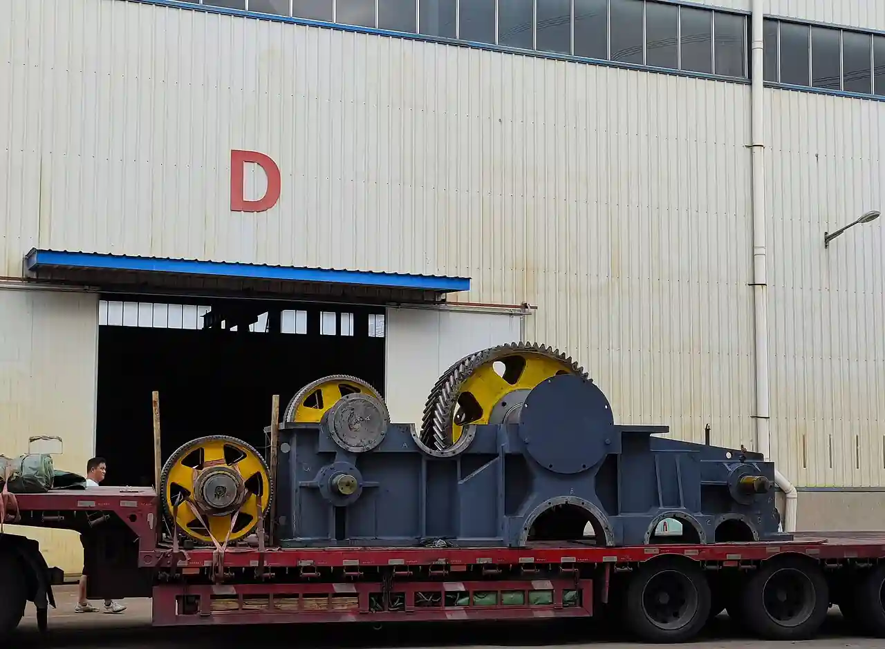
A steam turbine is a rotating machine that converts the heat energy of steam into shaft work by expanding it through rows of blades: steam enters at pressure and temperature, accelerates through nozzles and stationary vanes, pushes the rotating blade rows, and leaves at lower pressure having surrendered its enthalpy to the shaft. An industrial steam turbine turns that shaft work into electricity through a generator or into process drive through a gearbox on pumps, compressors, and fans. Condensing machines exhaust to a surface condenser under vacuum for maximum work per kilogram; back pressure machines exhaust at a pressure the process wants, delivering both power and steam; extraction machines take process steam from an intermediate stage while continuing to make power from what remains.
This page treats the steam turbine as a purchasing object: how inlet conditions and exhaust class size the machine, how speed, power, and the driven equipment set the mechanical design, how condenser, boiler, and governor interfaces define the plant around it, and how lubrication, gland steam, vibration, and overspeed protection keep a machine that runs at 3,600 to 12,000 rpm honest. It receives the steam the superheater raised and hands its exhaust to the condenser or the process header.
The decision concentrates in five places: the steam conditions available and the exhaust arrangement wanted, condensing, back pressure, or extraction, which together set the energy extracted per kilogram; the power and speed the driven machine demands; the control philosophy, governor and safety, that integrates it with the steam system; the rotor dynamics and mechanical interface, gearbox or direct drive; and the balance of plant, condenser, lubrication, and gland systems, that keeps it running. Get those right and the frame size, stage count, and blading follow.
Chapter 1 / 06
What a Steam Turbine Is and What Is Being Decided
The machine is a staged expander, and its anatomy is a century and a half of refinement. Steam enters through control valves, arranged in a chest with sequential opening for part load efficiency, expands through the first stage, often a partial admission impulse row, and continues through alternating rows of stationary vanes and rotating blades, each pair a stage dropping pressure and temperature while extracting work, until the exhaust hood discharges whatever enthalpy remains. The rotor carries the blade rows on a forged shaft supported in journal bearings, located axially by a thrust bearing, sealed at the shaft ends by labyrinth glands fed with gland steam. The casing holds it all against pressure and directs steam and condensate, and the whole rotating assembly is critical machinery on its own foundation.
Reaction versus impulse is the internal design vocabulary. Impulse staging drops pressure across the stationary nozzles and lets the jets push the rotating buckets, with modest pressure drop across the moving row; reaction staging drops pressure across both fixed and moving blades, with the moving rows acting as lifting airfoils; real industrial machines mix the two along the steam path as expansion demands. What the buyer sees is efficiency at load: stage design, part load valve arrangement, and the compromises of standardized frames. Industrial machines run isentropic efficiencies in the 70 to 85 percent class by size and duty, utility machines higher, and every point of efficiency is fuel or steam the plant keeps.
The driven equipment defines half the machine. Generator drive fixes speed exactly, 3,000 or 3,600 rpm for two pole generators on 50 or 60 hertz, or 1,500 and 1,800 for four pole, and the turbine becomes a synchronous island of precision. Mechanical drive leaves speed free but coupled to the process: a turbine driving a centrifugal compressor through a gearbox runs at its own optimum speed, varied by the governor to hold the driven machine's process variable, pressure or flow, and the train's torsional dynamics become a design case the purchase owns. A turbine on a boiler feed pump or a cooling water pump runs the same logic at smaller power, and the vfd driven ac motor alternative, cheaper to install, competes exactly where waste steam is not free.
What is being decided, in purchasing terms, is five things. First the thermodynamic duty: inlet pressure and temperature, exhaust arrangement, and power, which set the steam flow and stage count. Second the mechanical duty: speed, driven equipment, and the dynamics of the train. Third the control and safety philosophy: governor mode, overspeed protection, and integration with the plant's steam header logic. Fourth the machine's mechanical architecture: frame standardization, blade robustness, and bearing arrangement. Fifth the balance of plant: condenser or process header interface, lubrication, gland steam, and the turnarounds the machine will need. The paragraphs that follow work these in order.
Chapter 2 / 06
How Expansion, Staging, and the Rankine Cycle Do the Work
The turbine lives inside the Rankine cycle's promise: every kilojoule of enthalpy between inlet and exhaust conditions is potential work. Inlet enthalpy is set upstream, by the boiler or heat recovery steam generator and its superheater raising steam to design pressure and temperature; exhaust enthalpy is set by the arrangement, condensing machines dumping to a surface condenser at 30 to 80 millibar absolute, where the remaining enthalpy leaves as latent heat to cooling water, and back pressure machines exhausting to a process header at 3 to 15 bar, where the remaining enthalpy is the process's own supply. The difference, times the isentropic efficiency, is the work per kilogram, and the ratio of arrangements explains the market: a condensing machine extracts two to three times the work per kilogram of a back pressure machine, and a back pressure machine's exhaust is worth its fuel twice.
Steam rate is the sizing currency: kilograms of steam per kilowatt hour, roughly 4 to 6 for condensing duty and 12 to 20 for back pressure at modest conditions, read from the enthalpy drop and efficiency. Power demand over steam rate fixes the steam flow, and steam flow with specific volume, which swells a hundredfold across the expansion, fixes the blade heights and casing diameters stage by stage: small at the high pressure end, tall blades at the exhaust, and the machine's silhouette is the steam's own expansion drawn in steel. Wet steam in the last stages is the limit of that silhouette, because moisture erodes blades, and the maximum exhaust wetness the design tolerates, 10 to 13 percent class, sets the practical floor on exhaust enthalpy.
The governor is the machine's link to the plant's purpose. It holds speed on an islanded generator, follows load on a grid tied one, or holds the driven process variable on mechanical duty, modulating the control valves within milliseconds through a hydraulic or electric actuator. Overspeed is the failure it must never allow: a full load rejection on a generator accelerates the rotor hundreds of rpm per second, and the protection layers, the governor's fast valve closure, the independent emergency governor or electronic overspeed system, and the trip and throttle valve, exist so the machine never sees the speed at which its blades depart. Modern practice triples the protection and tests it on schedule, and the buyer inherits that practice in the specification.
The shaft end seals and the lubrication system are the machine's quiet necessities. Labyrinth glands hold the steam in with stepped clearances and a sealing steam supply, gland steam at low pressure on the shaft, arranged so air is excluded on vacuum machines and steam leakage is contained on pressure machines, the leaks routed to a gland condenser. Lubrication floats the journal and thrust bearings on oil at pressures and temperatures the bearing design specifies, delivered by main and auxiliary pumps through coolers, with an emergency dc pump or gravity tank behind them, because a turbine that loses oil at speed destroys itself in seconds and its bearings with it.
Rotor dynamics close the engineering. The train's critical speeds, the resonances of shaft and bearings, must stand clear of operating speed and its margins; the bearings themselves, tilting pad on modern machines, provide damping that keeps vibration low; and the monitoring, a vibration sensor pair at every bearing plus axial position probes, watches the machine's heartbeat continuously. Alignment to the driven equipment, thermal growth accounted, is the installation's gift to dynamics, and misalignment is the root of half the vibration complaints in any turbine hall.
A worked example fixes the economics that sell these machines. Take a plant letting down 40 tonnes per hour of steam from 40 bar at 400 deg C to a 10 bar process header through a valve: the enthalpy available across that drop, harvested by a back pressure turbine at 75 percent isentropic efficiency, is roughly 2 megawatts of shaft power generated from pressure the process needed removed anyway, every operating hour of the year. Against a motor buying the same 2 megawatts from the grid, the machine pays its capital back in one to three years at typical industrial power prices, and the only honest questions left are the steam flow's steadiness and the maintenance appetite of rotating machinery on the site. That arithmetic, run on the plant's own numbers, is the entire commercial case for the industrial steam turbine.
Chapter 3 / 06
Condensing, Back Pressure, and Extraction Designs and Duty Boundaries
The condensing turbine is the maximum work machine: it exhausts to a surface condenser, whose vacuum, maintained by the cooling system and its air removal, pulls the expansion as far down the enthalpy curve as economics and exhaust wetness allow. It suits power generation duty wherever the steam has no process customer, and its cost of the deep expansion is the hardware at the bottom: the condenser itself, the cooling water or air cooled system behind it, and the larger last stage blades the specific volume demands. The turbine condenser interface is a design marriage, exhaust area to condenser throat, and the pair is bought as one thermodynamic decision even when the purchase orders are separate.
The back pressure turbine is the industrial steam system's favorite: it generates power from a pressure reduction the process needed anyway. Steam raised at 40 bar for the turbine exhausts at 10 bar to the process header, and the plant takes the pressure drop as electricity instead of as valve noise and wear. The economics are almost embarrassingly favorable wherever the steam flow exists, because the alternative to the turbine is a pressure reducing valve that achieves nothing but the pressure drop; the sizing constraint is matching power potential to steam demand, and the extraction machine exists precisely when those two refuse to match.
The extraction turbine serves two masters by design: process steam leaves one or more intermediate stages at controlled pressure while the remainder continues expanding to condenser or lower pressure header. Controlled extraction holds the process pressure steady as load swings by modulating valves in the steam path, and the machine becomes the steam system's balancing organ, making power on whatever the process does not take. Double extraction machines serve two process headers; condensing and non condensing extraction variants cover the bottom of the cycle. These are the most flexible and the most instrumented of the industrial machines, and their governors hold two or three variables at once, power and one or two pressures.
Duty boundaries against the neighbors deserve plain language. The steam turbine is not a gas turbine, which burns fuel in its own combustion gas path and serves peaking duty with faster start and no steam system; it is not the ac motor or vfd drive train it competes with on mechanical duty, cheaper and simpler but blind to steam the plant must let down anyway; and it is none of the turbine word's distant relatives, the regenerative turbine pump and vertical turbine pump are water machines that share only the word, and the turbine flowmeter spins a tiny rotor to measure rather than to work. Upstream it receives what the superheater raised from the steam drum through the boiler's economizer fed work, and downstream it defines the condenser's duty and the cycle's cold end.
Class
Exhaust destination
Steam rate class
Where it wins
Watch-outs
Condensing
Surface condenser at vacuum
4 to 6 kg/kwh
Maximum power per kilogram, power generation
Condenser and cold end cost; last stage moisture
Back pressure
Process header at 3 to 15 bar
12 to 20 kg/kwh
Power from a pressure drop the process needs anyway
Power and steam demand must match; less work per kg
Extraction, condensing or non
Process tap plus condenser or header
Between the classes
Balancing power and process steam swing
Governor complexity; extraction control hardware
Start-up and load behavior deserve their own paragraph because they consume life and schedule. A cold turbine warms on specified ramps, casing and rotor growing at rates their differential expansion limits allow, soak points holding until metal temperatures equalize, the whole sequence hours long on large machines and tens of minutes on small; the piping warms and drains ahead of it, and the turning gear, the slow roll that keeps rotors straight through cooling, brackets every start and stop. Two shift operation, daily starts and stops, is a real duty class with its own design concessions, blade root and casing fatigue provisions, and it must be declared in the RFQ because a machine designed for base load that is cycled daily fails its calendar.
Chapter 4 / 06
Key Specification Parameters
The specification is built from the thermodynamics outward. The process set states inlet pressure and temperature, exhaust arrangement and pressure or vacuum, power output, and speed, with steam flow as the derived check. The performance set states guaranteed output at rated and named part load points, steam rates at those points, and the gland and leakage allowances. The mechanical set states frame and staging expectations, bearing arrangement and lubrication scope, gearbox scope if any, and the train's torsional analysis responsibility. The controls set states governor mode and range, overspeed protection philosophy, and the instrumentation list, vibration, axial position, temperature, and metal thermocouples. The commercial set states efficiency guarantee tolerances, erosion allowances, and the maintenance interval expectations.
Parameter
Typical range
Why it matters
Inlet pressure and temperature
10 to 100 bar, 250 to 540 deg C
The enthalpy the machine is given to work with
Exhaust pressure or vacuum
0.03 to 15 bar by class
The expansion floor; condensing versus process duty
Power output
0.5 to 150 MW industrial class
With steam rate, fixes the steam flow the plant must raise
Speed
1500 to 12000 rpm by duty
Generator synchronism or process optimum through a gearbox
Steam rate
4 to 20 kg/kwh by class
The fuel or steam cost of every kilowatt hour
Isentropic efficiency
70 to 85 percent industrial
The guarantee point the bids are compared on
Overspeed test margin
Per applicable practice
The protection layer that must never be needed
Vibration limits
Per standards on bearing housings or shaft
The machine's continuous health display
Two lines in that table decide the purchase's honesty. Steam rate at the plant's real operating points, not the rated point alone, because industrial turbines spend their lives at part load where valve losses and partial admission eat efficiency, and a bid that shows the curve beats a bid that shows a point. Exhaust wetness on condensing machines, because the last stage's erosion life is bought with the moisture the expansion tolerates, and the vendor's reheat or moisture removal provisions, if the conditions demand them, belong inside the frame's pricing rather than outside it.
Instrumentation is the machine's nervous system and it is specification-grade: a vibration sensor pair at each bearing plus shaft probes on critical machines, axial position on the thrust bearing, temperature elements in the bearings and on the casing expansion points, pressure and temperature transmitters at inlet, extraction, and exhaust, and the speed pickups that feed the governor and the overspeed systems independently. A flow meter on the main steam closes the plant's heat rate accounting. The historian that trends all of it is the machine's medical record, and the trip matrix that acts on it is written with the vendor and rehearsed with the operators.
Chapter 5 / 06
Selection Decision Factors and RFQ Language
Selection starts with the steam system's arithmetic. What the boiler raises, what the process demands at each pressure level, and what the gap between them is worth as power: the turbine class falls out of that triangle. A process with steady low pressure steam demand and a high pressure source wants back pressure generation on the let down; a power driven site with no steam customer wants condensing; a site whose process demand swings against its power wants extraction. The steam balance diagram is the document the machine is sized on, and it belongs in the tender package.
The driven equipment then fixes mechanics. Generator duty asks a standard speed and a standard interface; compressor and pump duty ask the train's optimum speed, a gearbox where it differs from the turbine's best, and a torsional study of the whole train that names whose responsibility it is, vendor, driven equipment maker, or a third party, because misassigned torsional analysis is the classic start-up discovery. The turbine's control mode follows the driven duty: speed or process variable on mechanical drive, load or frequency on generation, and the integration with the plant's distributed control through a plc or the governor's own electronics.
Steam conditions deserve one honest review before the RFQ goes out: the machine you can afford to feed. Inlet temperature is bought in the boiler's superheater and metallurgy, and specifying above what the plant will honestly raise, or below, wastes either the turbine's potential or the turbine's price; extraction pressures should match the process headers that exist; and the condensing vacuum should suit the cooling system's real annual range, because a condenser designed for 20 deg C water in a 32 deg C climate delivers its vacuum only in winter.
A complete RFQ states, on one process data page: inlet steam pressure and temperature with droop allowances; power output and speed; exhaust class and pressure or vacuum; steam rates expected at rated and named part loads; driven equipment interface and torsional responsibility; governor mode and range with overspeed philosophy; lubrication scope, reservoir, pumps, coolers, emergency supply; gland steam supply and drain arrangements; vibration and instrumentation standard to be met; coupling and gearbox scope; noise limits; and the applicable machinery standards and inspection regime. Vendors quoting against that page quote the same machine, and their steam rates, efficiencies, and scope boundaries become comparable line items.
Balance of plant belongs in the same decision: the condenser and its cooling system on condensing duty, a cold end choice, water or air cooled, whose annual performance curve the turbine's output rides; the boiler feed pump and feed train that return condensate to the economizer and steam drum; the desuperheater or attemperator that trim the header the exhaust feeds; and the safety relief valve and non return provisions the steam system needs around the machine. A turbine bought without its cycle is a rotor with promises.
The cold end choice on condensing machines is a selection factor hiding inside the turbine decision. Water cooled surface condensers deliver the deepest vacuum and the most output but need a cooling water system, its towers or river intake, its chemical program and its environmental scrutiny; air cooled condensers trade a degree or two of vacuum for independence from water and its permitting, and in hot climates the summer output loss is a real megawatt line in the economics. The turbine's guaranteed output is meaningless without the condenser's design conditions attached, and the pair should be specified and bid as one thermodynamic package with the annual temperature curve on the table.
Chapter 6 / 06
Installation, Standards, Failure Modes, and Maintenance
Installation is precision machinery work: foundations to specification with grout and anchor discipline, sole plates and casing set level, the train aligned cold with the thermal growth offsets the vendors computed, piping loaded onto the casing within the nozzle allowables, because pipe strain is the silent killer of alignment, and the lubrication system flushed to cleanliness the bearings deserve. Commissioning proves the overspeed protection on the first run, tunes the governor against the real load, and establishes the vibration baseline that every operating hour afterward is judged against.
The governing standards are the rotating machinery codes and the steam turbine practice they encode: the international machinery standards for steam turbines and their application, the vibration measurement and evaluation standards the instrumentation answers to, the lubrication oil cleanliness practice, and the grid codes the generator and governor interface must satisfy; vendors such as Siemens Energy document the industrial steam turbine practice on their product literature, and the applicable performance test codes govern the acceptance run. The buyer's protections are the standards named in the purchase and witnessed at test, and the performance test at the plant, run to the agreed code with the instruments calibrated, converts efficiency from promise to record.
Failure modes are rotating machinery's classics with steam's own signature. Vibration rising slowly is imbalance or misalignment or bearing wear, and the spectrum tells which; sudden vibration is a dropped blade or rub and trips the machine; thrust bearing wear shows in axial position and ends in rotor to casing contact if ignored; gland wear shows as steam leaks and vacuum loss; blade erosion on wet stages hollows the last blades over years; and governor problems show as speed or pressure hunting that the process feels before the operators do. Water induction, slug or spray entering from piping, is the destroyer that the startup drain discipline and the non return provisions exist to prevent, and every turbine operating procedure spends its first pages on it.
Symptom
Likely cause
First action
Vibration climbing gradually
Imbalance, misalignment, bearing wear
Trend spectra and phase; check alignment and oil condition; plan bearing inspection
Sudden high vibration trip
Blade event or rub
Do not restart; boroscope and open inspection before reuse
Axial position drifting
Thrust bearing wear or transient loads
Verify load and oil supply; inspect thrust bearing at next stop
Vacuum degrading on condenser
Air in leakage, fouled tubes, gland wear
Leak survey with helium or vacuum decay; clean tubes; inspect glands
Speed or pressure hunting
Governor valve or calibration fault
Check valve position feedback and tuning; verify calibration of transmitters
Routine maintenance is the discipline of rotating machinery: oil quality, water and particle counts, on a schedule the cleanliness standards set; vibration trend review monthly and analysis at every change; governor and trip system proving on the calendar, because untested protection is decoration; gland steam condition maintained; and the borescope and open inspections at the intervals the duty, wetness and deposits, suggests. Major overhauls, blade inspection and replacement, bearing renewal, alignment restoration, come at 50,000 to 100,000 hour class intervals by duty, and the plants that trend honestly predict them instead of discovering them.
The institutional item is the protection test that actually happens. The overspeed system, the trip and its sensors, is asked to work once, at the worst second of the machine's life, and the monthly or quarterly proving, the manual trip, the simulated test, the calibration of the electronic channels, is the only maintenance that buys that reliability. The operating log, starts, trips, load hours, water upsets, is the machine's biography that metallurgy reads at overhaul, and the operators who record it honestly hand the next overhaul its work list.
Spares and outage planning close the commercial picture. Carry bearing sets and thrust pads, gland seal segments, governor and trip system rebuild kits, instrument spares for the critical measurements, coupling elements, and oil system filters and coolers' spares; on remote sites add the rotor exchange option or a spare rotor if downtime economics justify, because rotor repair lead times are measured in months. Pre-agree the overhaul work scope templates with the vendor at purchase, inspection points and clearances to be recorded, so the bid-out outage contractor prices against a defined job, and the turbine's clearances journal, kept since commissioning, tells every future overhaul what the machine actually wears.
FAQ
Should I choose condensing, back pressure, or extraction?
Follow the steam balance: process steam demand against power demand. A pressure drop the process needs anyway is free power for a back pressure machine; no steam customer means condensing for maximum work per kilogram; swinging process demand against steady power wants extraction, which serves both. The class is chosen by the flowsheet, not by preference.
How does an industrial steam turbine differ from a gas turbine?
The working fluid and the duty. The steam turbine expands steam from a boiler or waste heat source, is tied to the steam system's economics, and rewards steady base load; the gas turbine burns fuel in its own gas path, starts fast, and serves peaking and simple cycle duty. Where waste steam exists, the steam turbine converts it to power no gas turbine can touch.
What steam rate should I expect?
Roughly 4 to 6 kilograms per kilowatt hour for condensing machines at modest industrial conditions and 12 to 20 for back pressure, set by the enthalpy drop and the isentropic efficiency the frame delivers. Vendors quote guaranteed points at rated and part loads, and the part load curve is the honest one to compare, because that is where the machine will live.
Why is gland steam supplied to the shaft seals?
Labyrinth glands need a sealing medium: on vacuum machines, steam blocks air ingress that would spoil condenser vacuum; on pressure machines, it contains leakage into a controlled drain path. The gland system, its pressure regulator and condenser, is small, cheap, and decisive for both efficiency and vacuum, and its condition belongs on the routine walk.
What protection systems does the turbine carry?
Layered and independent: the governor's fast valve closure on load rejection, an emergency governor or electronic overspeed system set below the mechanical limit, a trip and throttle valve that drops on oil pressure loss or any process trip, and the instruments, vibration, axial position, temperature, that initiate trips on mechanical distress. Each layer is proven by test on a schedule, because the worst second of the machine's life is the only exam.
Can a turbine replace my pressure reducing valve economically?
Often yes, and the arithmetic is straightforward: the let down flow times the enthalpy drop times the machine's efficiency is power recovered from a drop you were taking anyway. The back pressure turbine costs more than the valve and its payback is the power it generates against the steam system's hours; below some flow or utilization, the valve plus noise attenuation stays cheaper, and the line sits somewhere in the single megawatt class for typical industrial conditions.
What is water induction and why do procedures fear it?
Slugs or sprays of condensate entering a spinning turbine deform and break blades in an instant, and it arrives from piping that collected steam's own condensation. The defenses are startup drain discipline, drains open and verified before admission, non return and isolation provisions on interconnected headers, and the operating procedure's first pages, written by people who have seen the aftermath.