
Solar glass manufacturing is, at its control core, a patterned float line with a tempered downstream: Fe2O3 below roughly 200 ppm in the melt keeps solar-weighted transmittance above 91.5%, and a 1,000 t/day furnace typically runs a tin-bath atmosphere at 0.5–2 ppm O2, an annealing lehr held to ±2 °C across 600–700 °C, and a ribbon pull-rate of 600–1,200 m/h, with each loop closed on a process control transmitter on the lehr under ATEX 2014/34/EU zone 1 [S3].
Instrumentation engineers reading a solar-glass P&ID will recognize nearly every loop from a flat-glass line: Coriolis or vortex meters on the gas-side mass balance, sanitary sight glass at the lay-up station of the downstream PV laminator, and a differential pressure transmitter on the vacuum manifold pulled below 50 mbar absolute for the 145–155 °C / 12–18 minute press cycle [S3]. The procurement question is not whether solar glass needs process control, but which loops are spec-critical versus which can ride on the same hardware the plant already owns for architectural float glass.
Float-Line Control Loops: O2, Lehr Temperature, Pull-Rate
The three spec-critical loops on a solar float line are tin-bath oxygen, lehr temperature uniformity, and ribbon pull-rate, and the published 2026 spec map anchors each to a concrete control band [S3]. Tin-bath atmosphere O2 sits at 0.5–2 ppm because above 2 ppm the bottom surface of the ribbon picks up haze that erodes the 91.5% transmittance budget the cover glass must clear before AR coating.
Lehr uniformity is the second gate: ±2 °C across the 600–700 °C anneal window is the band that keeps residual stress low enough for downstream tempering at 620–680 °C, which must produce ≥90 MPa surface compression per EN 12150-1 on 2.0 mm or 3.2 mm cover stock [S3]. Pull-rate at 600–1,200 m/h is the throughput lever, and it is where the ribbon thickness gauge, the lehr pyrometers, and the roller-drive VFDs are coupled into one master speed loop, with process calibration drift on the pyrometers being the most common field failure mode a maintenance crew will hit on a 24/7 line.
Pattern Rollers, AR Coatings, and the 50–150 µm Optical Gate
Pattern-roller surface micro-structure is engineered to a pyramidal pitch of 50–150 µm and a depth of 0.5–3 µm at the float bath, and the AR coat that follows is a SiO2/TiO2 sol-gel layer that adds 1.5–2.5 percentage points of transmittance before the ribbon ever reaches the laminator [S3]. Procurement engineers evaluating a solar-glass line should compare on three criteria: roller-pattern supplier count, AR bath chemistry lifetime (typically 7–14 days between dumps), and tempering-line yield at sub-2.0 mm thickness, which is the 2026 cost-driver edge case.
For thin-film cell formats the spec widens: CIGS at 1583×660 mm and CdTe at 1400×1600 mm, with 2–3.2 mm glass thickness, a max conveying speed of 80 m/min, position deviation below 2 mm/m, and positioning accuracy of ±3 mm, all held by a six-axis robot with ±0.05 mm repeatability loading 5–20 kg substrates up to 2300×1300 mm [S4]. The instrumentation read-through is that the vision-alignment loop on the robotic loader is now a closed-loop control element, not a quality step, which changes where the multifunction process calibrator gets parked during a shift.
Continuous Tempering Furnaces: IPC Control and 3–5× Batch Throughput

Continuous tempering lines for solar cover glass are rated 3–5× higher than batch furnaces, run glass from 3 mm to 10 mm, use forced convection with ceramic elements rated to 1300 °C, and are governed by a high-stability Industrial PC (IPC) with multi-language interface and 220V/380V/415V, 50/60 Hz power compatibility for global deployment [S5]. The throughput claim is real because the steady-state thermal field eliminates the ramp/soak penalty of batch cycling, which is exactly where a discrete PLC with a fixed recipe loses to an IPC running a continuous profile.
The control-relevant spec gates on a continuous solar tempering line are: roller-driven constant velocity through heating and quench zones, synchronized high-pressure quenching aligned to conveyor speed, CE certification for the European market, and a custom build lead time of 80–100 working days [S5]. The line is built to run 24/7, and from a process-control standpoint the IPC is doing what a batch PLC cannot, namely holding a moving thermal profile on a non-stop ribbon without thermal overshoot at the seam where each new sheet enters the heating zone.
PV Laminator Loops: Vacuum, Press Temperature, Cycle Time
The midstream PV laminator that converts tempered cover glass plus EVA encapsulant into a module runs vacuum hold below 50 mbar absolute, press temperature of 145–155 °C, and press cycle of 12–18 minutes, with the EVA film specified to ISO 12543-1~6 and GB 9962 for laminated safety-glass interlayer behaviour [S3]. The instrument stack reads like a flat-glass laminator PID: a differential pressure transmitter on the vacuum manifold, Type J or K thermocouples in the platens, and a sight glass for visual confirmation of bubble-free lay-up before the press closes.
For module-format flexibility, automated conveying systems reach 1.5 m/s with online storage buffers holding more than 200 sheets, and an AI-vision system tracks cell position in real time to correct alignment, which is the lighting equipment and electric lamps class of machine-vision loop applied to glass rather than wafer [S4]. The spec gates that matter to a control engineer on this segment are: vision-correction latency, vacuum-leak rate per cycle, and the PID auto-tune behavior of the platen heaters under varying glass mass per batch.
Specification Comparison: Float Line, Continuous Tempering, PV Laminator
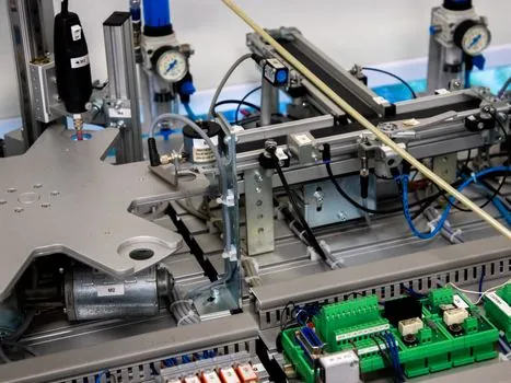
The three sub-systems line up against distinct decision criteria, and the comparison matters when a buyer is choosing whether to integrate a single vendor or split the scope. On the float-line segment the spec gates are atmospheric O2 (0.5–2 ppm), lehr band (±2 °C across 600–700 °C), pull-rate (600–1,200 m/h), and ATEX 2014/34/EU zone 1 on lehr instrumentation. On the continuous tempering segment the gates are glass thickness range (3–10 mm), throughput multiplier versus batch (3–5×), heating element ceiling (1300 °C), and IPC-based continuous control. [S3]
On the PV laminator segment the gates are vacuum hold (<50 mbar absolute), press temperature (145–155 °C), cycle time (12–18 min), and interlayer compliance with ISO 12543-1~6 plus GB 9962. Where the loops overlap, on a vacuum and temperature PID for instance, a plant can share a transmitter and a lamps and light fittings class inspection lamp across all three stations, which is the practical case for a single-vendor scope on a greenfield solar-glass module line [S3][S5].
Failure Modes, Constraints, and What the Spec Map Will Not Tell You
The published 2026 spec map is explicit on bands and tolerances but silent on field failure rates, and the three recurring control failures a maintenance team will face are: pyrometer drift on the lehr, AR bath chemistry exhaustion before the 7–14 day dump interval, and vision-system latency on the robotic loader that pushes positioning error above the ±3 mm gate at 80 m/min [S3][S4]. Each failure mode is detectable on a routine walk-down, but only if the right reference instrument is on site, and a multifunction process calibrator on the bench is the cheapest insurance against an unscheduled lehr shutdown.
Two further constraints are worth flagging before a procurement commitment: thin-film lines certified to 2006/42/EC carry a roughly 30% reduction in changeover time from the modular buffer architecture, but that saving is contingent on the AI-vision system being trained on the actual cell format, and the 80–100 working day lead time on a custom continuous tempering line is a hard constraint on any capex timeline that assumes a vendor-shelf delivery [S4][S5]. Buyers who fail to spec the vision-training scope or the lead time correctly will discover the gap during site acceptance testing, which is the worst time to learn it.
Where Solar-Glass Control Sits in the 2026 PV Stack
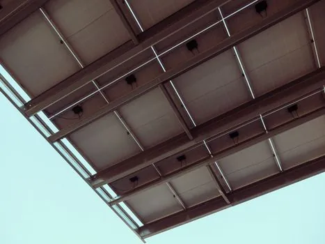
Solar-glass process control consumes the same construction machinery and equipment class of transmitters, flow meters, and IPC hardware that flat-glass and architectural lines already use, with the spec-critical additions being the tin-bath O2 probe, the EN 12150-1 surface compression test on tempered cover, and the ISO 12543-1~6 plus GB 9962 interlayer compliance on EVA film [S3]. For cross-stack context, a related breakdown of the cell-side cost structure is in Solar Cell Manufacturing Cost Breakdown: Silicon, Wafer, and Process Stack, and the upstream-to-laminator instrumentation map is detailed in Solar Cell Process Control: Furnace, Inline Test, and Lamination Instrumentation, both of which share transmitters and PLC architecture with the glass-side loops described here.
Trackable next nodes for 2026-09 onward: any vendor announcement on a shorter-lead-time continuous tempering line under 80 working days, any update to the EN 12150-1 surface compression threshold for sub-2.0 mm cover glass, and any revision to the ISO 12543-1~6 cycle-time envelope for EVA cure at sub-150 °C press temperatures, all of which would shift the spec gates mapped above [S3][S5].